

Slope445
-
Posts
71 -
Joined
-
Last visited
Content Type
Profiles
Forums
Blogs
Gallery
Calendar
Downloads
Everything posted by Slope445
-
Update for 1970s Sterling Schweizer 1-34
Slope445 replied to Slope445's topic in Scale and Semi-Scale kits
Final weight is ~56oz. Spoilerons are programmed in using the throttle stick. You can adjust the aileron neutral position from around 5 degrees down to about 40 degrees up but I haven’t used them while flying yet. And I’m not sure what the trim change will be if fully deployed upward. I’ve use this RG-15 airfoil before. It’s a good airfoil for slope gliders. Its on the airfoil tools website. On the 1-34, it’s thickened to slightly more than 11%. -
Update for 1970s Sterling Schweizer 1-34
Slope445 replied to Slope445's topic in Scale and Semi-Scale kits
Took it up to Temple Hill. -
Update for 1970s Sterling Schweizer 1-34
Slope445 replied to Slope445's topic in Scale and Semi-Scale kits
Here’s the video. FullSizeRender.mov -
Update for 1970s Sterling Schweizer 1-34
Slope445 replied to Slope445's topic in Scale and Semi-Scale kits
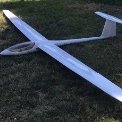
Finally did the maiden flight my version of the Sterling Schweizer 1-34! And it was wild. The CG was set at 61mm back from the LE. For the launch, I dialed in a bit of up trim also...probably a mistake. My flying buddy launched into a 5 to 10 mph breeze on my local slope. The first 3 seconds seemed fine. Then a tip stall followed by 3 or 4 more, major loss of altitude, no control, terminating in a vertical dive into the slope a few hundred feet down from the top!! 15 seconds of panic and thwack! It was so far down the hill I couldn’t actually see the impact and I assumed the worst. But after recovering the model (flying buddy John got it for me) it only had some dents and gouges in the nose area (fixable) and otherwise it seemed OK! I was shocked! My styrofoam, plywood and balsa construction approach is pretty tough! It was still flyable so we decided to add some more nose weight (1.5 oz more) and remove the small amount of up trim and go back to a totally neutral elevator position. Flight 2 produced the video here. Much better! At a 15oz/ft it flies fairly fast as you can see. I actually had to add in a fair amount of down trim (maybe 5 clicks) during the flight. I’ll probably shim the stab mount eventually and swap out some of the nose weight for a fiberglassed nose area. Here’s a photo prior to launch. The blue tape you see on the nose is an attempt to add more protection to the nose area. The slope is pretty rocky and harsh on models. This time of year the best way to land is to plow into the mustard weed as you can see in my landing. Typically I have trouble posting videos so it may take a while to post it. -
Cermark Phoenix - flying with lifting stab?
Slope445 replied to Slope445's topic in Gliders and Gliding - General Discussion
Anyone agree? Disagree? Comments? -
Cermark Phoenix - flying with lifting stab?
Slope445 replied to Slope445's topic in Gliders and Gliding - General Discussion
Well I found this free wind tunnel app (thanks Denis!). It’s got a lot of limitations but I was able to used their canned airfoil and draw in a flat stab that looks to have a slight positive incidence with respect to the airflow on the left of this screen shot of the results. Notice the blue (low pressure) over the wing and UNDER the stab. This means the stab is pushing down and illustrates the down wash effect as discussed by John S above! This little test doesn’t perfectly reflect the Phoenix setup but it’s kinda cool and it’s telling me that down wash effect is probably what’s going on. -
Cermark Phoenix - flying with lifting stab?
Slope445 replied to Slope445's topic in Gliders and Gliding - General Discussion
I’ll check it out. Thanks -
Cermark Phoenix - flying with lifting stab?
Slope445 replied to Slope445's topic in Gliders and Gliding - General Discussion
I did wonder about the down wash effect. I wasn’t sure how far away from the wing it extends. The Phoenix is a T tail so the stab is maybe 2 ft behind the wing and several inches above it. Assuming it’s in the down wash then it makes sense it’s pushing down. Denis, do you have a link or website for one of these wind tunnel apps? -
Cermark Phoenix - flying with lifting stab?
Slope445 replied to Slope445's topic in Gliders and Gliding - General Discussion
I think I may do more testing. Maybe I’ll attach a short string above the stab. Maybe an inch above it and away from the fuse. Then do some normal flight speed flybys and observe the angle of the string compared to the stab. Maybe video it. -
I’ve been interested in seeing if my Phoenix is flying with the stab producing down force as Im told should be the case for most gliders. So, I indirectly measured it in flight. By installing an AOA sensing vane, calibrated to the flat bottom of the wing and adjusting for the fact that the actual wing incidence is about 2 degrees more that that, I determined that during stable flight, the wing is flying at around 4 to 5 degrees incidence. However measuring on the bench, when the stab is horizontal (using bubble level), the wing is at 3.75 degrees. So supposedly when in flight, if the wing is at 4 to 5 degrees positive, the stab would be at +.25 to +1.25, thus producing a nose down moment instead of a nose up moment as expected. The CG is at a location where the plane flys fine. What’s wrong here? Nothing?
-
Update for 1970s Sterling Schweizer 1-34
Slope445 replied to Slope445's topic in Scale and Semi-Scale kits
Nope. Not yet. The 1-34 is aging like a fine wine. Waiting for the perfect day to pop the cork! I have noticed that the Ultra coat covering I used needs reshrinking AGAIN and is so thin you can see the balsa grain, etc right through it. ? But, couldn’t find monokote. -
Update for 1970s Sterling Schweizer 1-34
Slope445 replied to Slope445's topic in Scale and Semi-Scale kits
Well I’ve decided to just go for broke and slope launch it. I’ll have one of my flying buddy’s launch it so I can be ready for any serious trim problems. Ive done maiden flights like this before and I’ve only had 1 incident and I threw it myself that time! ??? -
Update for 1970s Sterling Schweizer 1-34
Slope445 replied to Slope445's topic in Scale and Semi-Scale kits
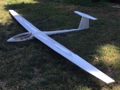
Ok. Finally maiden flight ready! Here’s a photo of the finished aileron servo faring and a shot of the whole airframe. The pup got in the way so he’s a bonus! I added hinge tape to the underside of all hinge lines (except the rudder) to stop air from bleeding through. Final weight is 56 oz. Wing loading is 14.8. That’s higher than I wanted but should be OK for slope flying. The wing is an RG 15, 11% thickness and is set to an incidence of 3.75 degrees when the stab is at 0.0 degrees. Ill try try to get some video of it flying but that may be a while since winds this time of year are typically not good. Here’ hoping for an event free maiden flight! -
Update for 1970s Sterling Schweizer 1-34
Slope445 replied to Slope445's topic in Scale and Semi-Scale kits
Fuse painted! Radio installed. Decided to tweak the linkage a bit to better tie down the putter sleeves. Didn’t like the way the elevator “tape” hinge came out so I’m changing it to standard piano hinges installed the same way I did the aileron hinges. -
I like the batteries! Modelers don’t throw anything heavy away! Gallon cans of extra paint, chunks of lead, steel, stacks of old magazines...I’ve used them all. ?
- 73 replies
-
- 1
-

-
- balsacraft
- fw190
- (and 1 more)
-
Update for 1970s Sterling Schweizer 1-34
Slope445 replied to Slope445's topic in Scale and Semi-Scale kits
Well I’ve had a small case of 95%itus. A project gets 95% complete and your enthusiasm to finish it drops to 5%! But I finally got back on this. Final installation of the aileron servos requires that the servo leads be shortened. So that’s what you see here. The wire splices are staggered so insulating over the individual splices isn’t necessary. This saves a little volume when storing the excess wire. There’s enough slack such that the servos can still be removed, worked on, etc. The service loop of wire is stored in a small volume just next to the servo. Still need need to finish covering the wing, paint the fuse and firings and a few other things. Then it’s time to test glide!!!! I can’t wait! -
Update for 1970s Sterling Schweizer 1-34
Slope445 replied to Slope445's topic in Scale and Semi-Scale kits
The next step is to permanently install the ailerons. The temporary aileron installation, used to setup the servo mounting, ball link height and push rod length, is undone. Then the hinges are trimmed and drilled for final installation. After preparing the hinges, they are epoxied to the aileron using a two step process where after the initial gluing, holes are drilled through the existing hinge holes and into the aileron. More epoxy added and allowed to soak through the holes and down into the spar. 1 hour epoxy is used. This makes a sort of epoxy “nail” for some extra bonding strength. The wing is partially covered now. Seemed easier to cover the hinge line before the aileron is attached. After covering the wing is placed in the upper core bed, the aileron lined up and then CA’d in place with just a small drop of CA on each hinge. The the wing is removed and checked for good aileron alignment. If the alignment is not acceptable, the glue joints can be snapped and tried again. If things are good, 1 hour epoxy is applied and allowed to soak through the holes on the wing side. I flubbed up with the CA on one hinge (glued it together!) and I didn’t realize it until after I had epoxied it! Had to redo that hinge. I had to slice it with a Dremel tool and do some surgery. It wasn’t easy and showed me that the epoxy “nail” thing worked pretty well! -
Update for 1970s Sterling Schweizer 1-34
Slope445 replied to Slope445's topic in Scale and Semi-Scale kits
I had to come up with a 2 piece aileron servo fairing. I can’t move the servo forward since I’d be cutting into the carbon spar so a part of the fairing has to be on the aileron. I didn’t want a big gap so I made the aileron part fold into the forward fairing piece. The gap stays closed for aileron movement during general flying maneuvers. i glued a hard fiber board disk to the wing skin to give the hold down screw something to bite into. I’ll put tape over the curved opening the fairing doesn’t cover -
Update for 1970s Sterling Schweizer 1-34
Slope445 replied to Slope445's topic in Scale and Semi-Scale kits
Video finally worked. Using a higher speed internet connection from a different location. -
Update for 1970s Sterling Schweizer 1-34
Slope445 replied to Slope445's topic in Scale and Semi-Scale kits
IMG_5621.MOV -
Update for 1970s Sterling Schweizer 1-34
Slope445 replied to Slope445's topic in Scale and Semi-Scale kits
Well the video won’t upload so it’s not available ☹️ -
Update for 1970s Sterling Schweizer 1-34
Slope445 replied to Slope445's topic in Scale and Semi-Scale kits
I usually mock up control linkages for ailerons, as I did here, before making the final assembly. I like the ball link approach and have used ball links for ailerons before. Mocking up let’s me get the ball the right distance above the surface and get the push rod length correct and bent properly if needed. The dowel the ball is threaded into is just tack glued in so I can pop it out and sand it down if I need to. The mock-up push rod here is simply made from a large paper clip. The threaded rod end is CA’d to the mock-up push rod. When I’m done playing with things, I’ll have the details needed for the final fabrication and installation. I’m setting up the model with spoilerons. Gotta have a way to get down if I happened to get into a killer thermal! You can see me playing with that in the video. I think it’s all good to go. -
Update for 1970s Sterling Schweizer 1-34
Slope445 replied to Slope445's topic in Scale and Semi-Scale kits
I’m cutting servo openings in the bottom of the wing. I like to keep them as small as possible. Sometimes I just epoxy the servo directly into the wing but that can be problematic. Gluing with RTV can work but I’ve had that approach loosen after a few years. But a broken servo can be pried out if necessary. However, it’s best to mechanically install the servo so it can be taken out if necessary. I made a small servo bracket from 1/32 ply. It holds the servo and prohibits movement in all 3 directions but the servo can still slip out by removing the screw. The servo bracket is glued in using Gorilla glue. That type of glue is kind of like an expanding foam so it fills in any void between the ply and the 1/32 balsa wing skin. If you’re not careful, you may cause a dent to be visible on the upper surface right where the servo cutout is so this glue avoids that problem. The connector for the previously installed servo extension lead is just under the curved portion of the cutout. Even these tiny servos stick out of this thin glider wind so I’ll make some fairings after fabrication the linkage. -
Update for 1970s Sterling Schweizer 1-34
Slope445 replied to Slope445's topic in Scale and Semi-Scale kits
I like the result. Plenty of up and down throw and the installation produces a nice tight hinge line. I need to install the servos next and get the linkage setup. I decided it’s easier to cover the wing and ailerons separately, before permanently installing the ailerons. So, I’ll get the servos installed and setup using the temporary aileron installation for now. -
Update for 1970s Sterling Schweizer 1-34
Slope445 replied to Slope445's topic in Scale and Semi-Scale kits
A small notch is filed filed into the aileron and the aileron spar to recess the hinge. Final assembly will have a hinge at the root, middle and tip. I only installed a hinge the root and tip for this test