Leaderboard


Popular Content
Showing content with the highest reputation on 02/07/22 in all areas
-
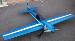
From an original by Roger Bale, circa 1998, to this:- # I wonder what happened?? To this 121 " span, zenoah 80 power and 38lbs! Strictly non aerobatic, it 'preambulates with purpose' The flag can be raised in flight and the Nav raises his hand to the onlooker In terms of storage and transport, its a bit of a monster!11 points
-
Many years ago, probably at the recommendation of Brian Winch, bless his soul, I bought an expensive Sheldon engineering USA test stand. Still in perfect use today...thank you Mr W. That test stand has been one of my trusty companions throughout my modelling life over the decades. Just had to say... D3 points
-
It can easily be answered by my favourite quotation "Those who the Gods seek to destroy, First they make mad!" And my favourite prayer: "OK, You have sent them all mad! Now for Pete's sake get on with the destruction part!!!"2 points
-
A steerable nose wheel makes ground handling so much easier. I always install a separate servo and programming it as a separate function on the radio makes the set-up easier. I use a servo-saver which is a spring that takes out the shock loads on landing. I make my own but you can buy them. The tension is adjustable by compressing the springs between the collets.2 points
-
ED carbs are an excellent upgrade. Easy to set up; Fabulous throttle response, and a useful power increase. Weston UK sell them.2 points
-
Hi all ! Another month has passed and the wing shells are about to being closed ! Sinds the last post i installed the wiring for servos , lighting , and retracts. This wing is ready to be closed after i dry-fitted the top shell (out of the mould). Before glueing the two halves together , i prepaired the second wing , thesame way , and made copies of all the parts needed for future wings. The second wing (R) I used some tape to protect the wiring from epoxy when closing the shells. The last test , to see if the ribs dont touch the top shell , or the gap between ribs and shell isn't too big (to much glue ),is done by placing a small plasticine ball between ribs and shell ,before dry fitting the top shell (in the mould ). After closing ,bolting together, and seperating the moulds again ,you can see how much the plasticine ball is crushed. In this case , the ball is reduced to aprox. 1mm , just fine !! This is done in several spots , just to be sure . Touching ribs make the wing surface bumpy ! Too much glue is ballast !! That's all for today , tomorrow is closing time !!2 points
-
Had to make a tank cradle today they wasn’t anything in the kit to support the tank. Tweaked it in a few places but now can remove with the tank attached to the cradle. All the 2mm holes are just to make sure l can screw it down without hitting a gap in the framework.2 points
-
I just be mad! I had the opportunity to buy a part started one of these kits and it was too good to pass up so I will be collecting it sometime this week to add to the list of builds! I will need a new engine to power it and am thinking of a 360v Laser (unless Jon can persuade his boss to let him build a Laser 400 radial - please oh please) but have read in the instructions and other builds that it is not unusual to have to add 3lb of lead to the nose!!!! Looking at the plans it does seem like there is a lot of potentially excessive material in the rear end so I may be able to lighten it somewhat with some careful planning, just take a look at these extracts from the plans. As a general rule it appears that all sheet covering for wings, tail and fuselage is 3/32" balsa sheet. The other thing that I want to change is the wing, it is approximately 86" long and is one piece so transporting and storing will be a pain so I'm thinking of splitting it into a central panel (the 'gull') and two outer panels and before you suggest it I'm not going to have folding wings! My thoughts are as shown in the attached I would really welcome comments and ideas from you guys about the above points I have raised. I should add that the partly built bit is the wing which, as far as I can make out, is 90% built but I'm not concerned about taking a saw to it!!1 point
-
I used a separate small metal geared servo driving the steerable wheel through a plastic snake which seems to protect the servo. Its had a few knocks! I set it up using Mike Holts advice from his writings on Futaba Transmitters. The servo is run through a spare channel on the receiver (5) which is slaved to your rudder channel (4). This lets you set up a lot of expo, on 5, so near the center of stick movement you only get a very small amount of deflection on the wheel, which is all you need as Brian says above. And then when taxiing at slow speed with full deflection you can still turn easily. You also use the sub trim on your spare channel to align your wheel so the model tracks straight as you taxi.1 point
-
every time i open my eyes i want to vomit........the doctor says its see sickness..... ken anderson,,,,ne..1....... see sick dept.1 point
-
Just Google " Weston UK" or give them a ring on 01795 522020 or 01795 521030. The link for the ED carb is Weston.co.uk/Ed-Carbs-/1 point
-
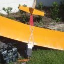
Hi Nigel, I built a Mannock from a DB kit powered by a Merco 61 back in the day. As ever when I build from a kit or plan I made a number of mods. Some of the mods were simply cosmetic as I wanted it to resemble a typical German LFG Roland biplane. I mounted the engine with zero-zero thrust offsets, reduced dihedral with ailerons on top & bottom wings also the wheeled undercarriage was interchangeable with floats. Each pair of wings were peg and 2 bolt fixed, a single servo mounted on the lower wing served all four ailerons. The sprung axle worked so well that I later copied a version of it to use on my Flair Magnattila. I found that suitably sized "O" rings worked just as well elastic bands but were more durable. Not too long after I built the Mannock I was on a model flying week holiday organised by RCM&E. I met David Boddington (in the bar)one evening & mentioned that the Mannock plan had no cg shown. Turned out that I had an early version kit but this led to a discussion on, amongst other things, why David's models often had large downthrust angles. The basic reason boiled down to his models being designed to be flown by pilots with a range of abilities from the relative novice up. Which meant a fairly forward cg with wing/tailplane incidences to cater for this, leading to the use of generous engine downthrust angle. This use of downthrust was/is a legacy from FF & single channel days when it was a means of automatically limiting any tendency for the nose to pitch up with too much power. But of course good throttle control effectively eliminates this need for downthrust. Here's a couple of photos of my Mannock on floats & close ups of my Magnattila U/C. Excuse the rough untidy appearance they were taken during the model's refurb & conversion from many years of ic power to more civilised clean electric power. Also, don't know if it's any help but I've attached a pdf file I made of the Mannocks building instructions.Mannock Manual.pdf1 point