

Slope445
-
Posts
71 -
Joined
-
Last visited
Content Type
Profiles
Forums
Blogs
Gallery
Calendar
Downloads
Everything posted by Slope445
-
Update for 1970s Sterling Schweizer 1-34
Slope445 replied to Slope445's topic in Scale and Semi-Scale kits
Aileron hinging I wanted to hinge the ailerons at the top edge as I usually do but I didn’t think slotting them in just below the 1/32 balsa skin was going to work too well. So I decided to mount them on the underside by bonding them to the spars. I also decided to install one aileron with simple tack gluing first to see how it was going to work out. -
Update for 1970s Sterling Schweizer 1-34
Slope445 replied to Slope445's topic in Scale and Semi-Scale kits
So a balsa spar is glued to both the aileron an the wing. The raw spar material has the top edge sanded at a angle and glued to the underside of the top skin. It’s also glued to the foam and the bottom skin (see photo). The spars are trimmed and sanded after installation. The hinges will be installed from below as shown below, after the spars are notched. I discovered that these Dubro hinges will not fold flat against themselves and that may limit down travel. That’s one reason to try this out first. If everything is good, the hinges will be trimmed down, more gluing holes added, then epoxied in place. Everything is only tack glued currently. -
Update for 1970s Sterling Schweizer 1-34
Slope445 replied to Slope445's topic in Scale and Semi-Scale kits
Finally getting back to the Schweitzer. Cutting out the ailerons is the next step. I cut them somewhat longer than scale since I’m more interested in flying performance than in keeping it strictly to scale. They’re 22 inches long as opposed to the 14.6 inches shown on the plans. After they’re cut, the underside skin in cutback another 1/4 inch on each side to make room for a 3/32 balsa aileron spars. -
That’s an idea. I’ll check into it. Thanks Dale
-
At some point I may have to sell off some of my sailplanes and gliders. I’ve read that do to the large wings and associated large shipping container, shipping costs may render my guys unsellable! I’m talking about 2m one piece wings up to 4m scale ships. Anyone know how to overcome this problem?
-
I’ve got about 20 flights on my Phoenix 2400, but I’ve recently had an intermittent aileron servo. Turns out there’s an in-line connector about 1/2 way out on the wing panel. Mine had partially disconnected!!! On one panel the connector was glued in and couldn’t move but on the other panel, it wasn’t glued or it came loose. Suggest you cut the white tape at the connector location and check it. Luckily the connector was making contact during all my flights!!
-
Update for 1970s Sterling Schweizer 1-34
Slope445 replied to Slope445's topic in Scale and Semi-Scale kits
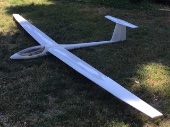
Ok. The Schweizer is about 90% complete. I made the wing fairing. All that’s left now is to cut out the ailerons and install the aileron servos, cover the wing/stab and do final finish and paint the fuse. I sure I’ll be flying it before painting because, as usual, I can’t wait to see how it flys! Weight has come out at slightly less than 43 ozs. It will need a little nose weight but it’s close to proper balance with just the battery installed so I don’t expect much more weight. We’re looking at a wing loading of less than 12oz/sqft. That’s not bad although I was aiming for around 8. An interesting coincidence: I ran across the original Sterling kit, in the vintage stack at the local hobby store ?. There’s a price of $299 on it!! ??. I guess I came out ahead because I only spent ~$200? on my version ?maybe... I started getting interested in building this around last November. It became my pandemic plane. I worked on it several hours a week. Hopefully I’ll post some successful test flight results soon! -
I realized I have a photo of my hot wire cutter that shows the glass idea. The top cut has just been made here. You can see the wire on the left (also has a fishing weight to keep it down). The glass plate is seen on the right. I’ve made several sailplane wings with this.
-
Update for 1970s Sterling Schweizer 1-34
Slope445 replied to Slope445's topic in Scale and Semi-Scale kits
Wing mounting You may know that the 70s kit wing attachment method was to hard glue around a 2ft wing center section to the fuselage. Then the long “tip” sections were slid onto wooden dowels and tongues. As happened to my old Schweizer 1-26 which used a similar wing attachment method, when those dowels or tongues break... you’re screwed as fixing the damage is very difficult. So I wanted a more conventional and up to date wing attachment approach. So since I’m going with a 2 piece, removable wing, I had to come up with a suitable wing mount. I wanted an approach that would allow slight tweaks of incidence, alignment with the tail surfaces and squareness with the fuselage. I came up with a scheme using 2 vertical wing mount brackets to fit into slots in a wing mount plate. Slots are cut with this drill press/ mill vice rig. A dremel saw cutter is chucked up. Once in the slots, the brackets can be moved slightly, up and down and forward and back until the wing is aligned perfectly. Then the brackets are CA glued to lock them in place on the mounting plate. Then the plate is removed and some gussets are epoxied on the back side. -
Oh those darn puppies!!! Always in trouble.... This is my “assistant” holding me down in my recliner until he thinks is playtime.
-
I thought I had some profile setting wrong and the “hand” (which looks like the classic STOP! hand motion to me) meant something like : “comments not accepted. Do not respond!” From the link: “Also the "hand icon" for recently joined members has received quite some negative feedback. It is misinterpreted for restrictions being in place instead of a waving hand (what I suppose it should be taken for).“
-
I’ve used the tipped up (like 70 degrees) aileron method on my 100 in. Ventus. An added on, contoured, thin piece of fiberglass installed on the top of a 2 meter Phoenix and a tipped up central flap method on a 100 in. Trendy. All worked well to dump altitude.
-
Update for 1970s Sterling Schweizer 1-34
Slope445 replied to Slope445's topic in Scale and Semi-Scale kits
Ok getting close to done. Sheeting is completed for each wing panel. I vacuum bagged some of it after using contact spray. Otherwise I just used weights. If I had to do it again, I’d vacuum bag where possible. The is no LE or final sanding in these photos. There is an incidence alignment tube toward the rear of the root ribs. These tubes are being epoxied in place, after matching the incidence for each panel. This is what being done in the photo where both panels are seen. -
Hours? It’s supposed to be a clock??? What? I’m not tracking.
-
Update for 1970s Sterling Schweizer 1-34
Slope445 replied to Slope445's topic in Scale and Semi-Scale kits
Time to install aileron servo wiring. I usually make a custom extension wire but this time I decided to just buy them. 24 in. extensions were a little too short so I had to add an additional 3 in. extension. The wire is placed into a slot cut into the top of the core but only after most of the bottom sheeting is installed. I was worried that cutting the wire slot may weaken the core too much and cause the airfoil to distort so the bottom skin went on. The inline connection is glued to a piece of 1/64 ply so it can’t come apart. The servo end is placed into an indentation cut into the foam and covered with 1/64 ply. Later when I cut a servo hole from the underside, the aileron servo wire will be loose. The ply pieces are inset and made flush with the wing surface. -
I use a homemade setup a little like Ron Gs. Differences are, instead of wheels, my cutting bow is held off of the table with a pan head bolt that rides on a piece of glass for almost no friction. I also use a Variac transformer for voltage (current/heat) adjustment. I usually use around 24vac when cutting. 18 in. wire. Can’t recall wire size at the moment.
-
And what does the little hand mean?
-
Update for 1970s Sterling Schweizer 1-34
Slope445 replied to Slope445's topic in Scale and Semi-Scale kits
For the balsa trailing edge I glued a piece of 1/8 X 1 in. balsa to the edge of a piece of 1/32 balsa sheet. This assembly was then glued to the bottom TE of the core using spray contact cement. Before applying any top surface sheeting, the 1/8 balsa was sanded down and feathered in to the contour of the core. The top sheeting was then applied over the top so the original 1/8 balsa, now a triangular cross section, is sandwiched between the top and bottom sheeting. Since I was using the contact cement, and you can’t easily reposition anything after it sticks, i made and installed some temporary alignment dowels. This allows the core to slide down over the dowels to get perfect alignment the first time. The small brass tubes/ply bases are only tack glued and popped off afterward. Then the dowels are cut off. The balsa TE assembly is set on the bottom core bed when ready to do the bonding and the wing core is installed from the top and weighted down. -
Update for 1970s Sterling Schweizer 1-34
Slope445 replied to Slope445's topic in Scale and Semi-Scale kits
Yes. I tested it by gluing the carbon to a scrap of styrofoam and pulling in the long direction of the tape until it failed. The foam failed leaving pieces of foam stuck to the carbon strip. I used the type of Gorilla glue shown here. I also roughed up the carbon before gluing. -
Update for 1970s Sterling Schweizer 1-34
Slope445 replied to Slope445's topic in Scale and Semi-Scale kits
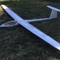
The next step is to add the carbon strips. These are about 5/8 in. wide by about 0.010 and run the entire length of the core. I did not try to embed them. They are so thin the plan is to simply sand out any trace of them appearing on the sheeting. I set the raw cores on the fuse to get a sense of the “look” again. The wings are like wet noodles at this stage. The carbon is glued on using the Gorilla glue. Epoxy would be fine but I hate mixing that much epoxy. After the carbon is glued on I can hold the core level by the wing tip. Very stiff. -
Update for 1970s Sterling Schweizer 1-34
Slope445 replied to Slope445's topic in Scale and Semi-Scale kits
Since the Phoenix wing rod I plan on using is straight, I built in some dihedral into the wing tube mount. The tube is angled slightly downward within the wing. This gives about 3 degrees of dihedral. To install the wing tube, the core is cut about 8 in from the root. The a sub rib is installed at that location. I also designed in some reinforcing sub spars at that location. After the tube and ribs are epoxied in, the tip portion of the core is epoxied back on. The photos should be self explanatory. -
Update for 1970s Sterling Schweizer 1-34
Slope445 replied to Slope445's topic in Scale and Semi-Scale kits
Wing cores are hot wired using a standard method. I make a two piece template. Cut the top, remove the top template, then cut the bottom surface. I use a homemade version of a Feather Cut hot wire cutter. Since I wanted a balsa TE I cut off a 1 inch strip of the TE foam after epoxying the core sections together. There’s also about 2 degrees of washout cut in. -
Got it MattyB. Thanks
-
?
-
How does one change your user photo? All I get is the green circle with my first letter in it. I can’t find where this can be changed.
