

Slope445
-
Posts
71 -
Joined
-
Last visited
Content Type
Profiles
Forums
Blogs
Gallery
Calendar
Downloads
Everything posted by Slope445
-
Update for 1970s Sterling Schweizer 1-34
Slope445 replied to Slope445's topic in Scale and Semi-Scale kits
Wings The wing construction I’ve chosen for the Schweitzer is styrofoam with carbon spar strips, 1/32 balsa sheeting and plywood root and sub rib. The TE is balsa as well as the LE. Wing mounting tube is brass. Adhesives used are spray on contact cement, wood glue, epoxy and water activated Gorilla glue. The styrofoam is typical hard styrofoam found in a arts and crafts store. It comes in blocks that are 2 in. X 28 in. X 12 in. For this model That’s enough for one wing panel. Since my hot hot wire cutter only has an 18in wire length, I had to cut 3 pieces to make a wing core. Here I’ve cut the raw trapezoidal blocks and laid them out by the fuse to get a feel for how the model looks and make sure my “scaling” and tracing the wing outline from my IPad doesn’t have some gross error. I’m pretty sure it’s OK. -
Update for 1970s Sterling Schweizer 1-34
Slope445 replied to Slope445's topic in Scale and Semi-Scale kits
Before starting into the wing design and construction, it’s worth noting that including the fuselage, tail surfaces, servos and battery and excluding the wing, wing rods and wing mount, we’re weighing in at about 16 ozs. I like it! -
Update for 1970s Sterling Schweizer 1-34
Slope445 replied to Slope445's topic in Scale and Semi-Scale kits
Still looking for minimal weight, I used the tiny Hitec servos for rudder and elevator. I made adaptors so they’d fit in an old plastic servo tray with a switch mount area. The tray can be removed for access to the forward battery compartment. After the canopy fell out a few times I decided I’d better make a latch. I put it together using a few pieces of brass tubing, a spring, a C clip and a nail. The latch can be removed so the servo tray can be removed. The brass pin catches a hole in a piece of basswood added to the center of the canopy. I have to admit, grabbing that nailhead can be tough. I may have to come up with a retrofit! -
Update for 1970s Sterling Schweizer 1-34
Slope445 replied to Slope445's topic in Scale and Semi-Scale kits
Thanks Murat. More details on the 1-34 build to come. -
Update for 1970s Sterling Schweizer 1-34
Slope445 replied to Slope445's topic in Scale and Semi-Scale kits
Except for more foam on the bottom bays, the fuselage basic structure and tail components are complete. I tried to make the internal rudder linkage work but struck out. There was way too much slop so I routed it externally. I think a ball link would have worked but too late now. The internal linkage for the elevator worked out fine. -
Update for 1970s Sterling Schweizer 1-34
Slope445 replied to Slope445's topic in Scale and Semi-Scale kits
Next whip up a canopy frame - all balsa and styrofoam. I recently ran across an online vender that sells a clear canopy! But this solid canopy is fine. -
Update for 1970s Sterling Schweizer 1-34
Slope445 replied to Slope445's topic in Scale and Semi-Scale kits
These photos show the stab mounting block and the vertical fin mounting block. The blocks are both 1/4 inch bass wood, epoxied in place. The stabilizer is bolted on using nylon bolts. I made it removable in case it needs shimmed later. It also seemed very small so I can replace it with a larger stab if necessary. Before permanently installing the fin, a small faring is made (see photo) A small balsa form fits around the fin. Foam is added and the fairing is tack glued in place for final sanding without the fin getting in the way. After the fin is installed, the faring is installed. -
Update for 1970s Sterling Schweizer 1-34
Slope445 replied to Slope445's topic in Scale and Semi-Scale kits
Here you can begin to see the overall look of the fuse “bones”. I put in a 1/16 balsa web piece across and between the formers to stiffen the rear fuse. I alternated between the top and bottom to save weight. I also added a spruce stringer since I wanted more strength right at that narrow point in front of the fin. The fin and stab are also cut out and placed in position just to get a look at them. No lightening holes yet. -
Build your own telemetry sensors.
Slope445 replied to Chris Bott - Moderator's topic in Gadgets and Electronics
I just happened to run across this forum. I’ve always been interested in onboard sensors. I’ve used the Spectrum vario in my sailplanes and it works. I built my own airspeed sensor a few years ago using a pressure sensor chip, an op amp and a bar graph. Then I did an onboard video recording of the readings. You can see a video and photos on RCgroups. Just search my user name “Slope445” -
Update for 1970s Sterling Schweizer 1-34
Slope445 replied to Slope445's topic in Scale and Semi-Scale kits
The plans do not show the profile of the nose cone. So, I sketched out a profile I thought looked about right. I think it’s actually longer than the one that came with tho original 70s kit but it’s ok. i made some hard balsa forms, glued them to F1 and filled in the 4 quadrants with softer balsa. -
Update for 1970s Sterling Schweizer 1-34
Slope445 replied to Slope445's topic in Scale and Semi-Scale kits
This shows things at about the 90% shaped level for the nose area. -
Update for 1970s Sterling Schweizer 1-34
Slope445 replied to Slope445's topic in Scale and Semi-Scale kits
I added a 1/16 shear web in the nose area to stiffen it and provide a surface to glue the foam to. Then add styrofoam and start shaping. The foam sands down quickly. -
Update for 1970s Sterling Schweizer 1-34
Slope445 replied to Slope445's topic in Scale and Semi-Scale kits
Still need to add formers 4 and 5 in this view. -
Update for 1970s Sterling Schweizer 1-34
Slope445 replied to Slope445's topic in Scale and Semi-Scale kits
Fuselage sides are added next. The sides are cut from patterns traced off of the Outerzone plans. I used 3/32 bass wood for the front portion and 3/32 balsa for the rear section. Due to the length of this fuse, there’s a splice under the wing. I thought about moving the splice but I left it where the plans had it. I did reinforce the splice with a 1/16 ply strip. After the sides are epoxied, the rest of the formers can be added. -
Update for 1970s Sterling Schweizer 1-34
Slope445 replied to Slope445's topic in Scale and Semi-Scale kits
Here are the first steps in assembling the fuselage. The nose area structure is 1/8 in plywood, epoxied of course. The keel piece is copied off the plans and is 2 pieces of ply. There’s a splice under F3 with a reinforcing piece added. -
Update for 1970s Sterling Schweizer 1-34
Slope445 replied to Slope445's topic in Scale and Semi-Scale kits
The Outerzone plans do not show outlines of the formers. Not sure why that is. So I had to make my own outlines. A study of the plans shows there are flat fuselage sides from which you can measure the height of the formers both above and below the flat sides. Once you have those measurements you can sketch the formers. I just assumed the fuselage was an oval cross section above and below the flat sides and the finished fuselage came out looking fine. Note that former 1 appears to be a circle on view you can see on the plans so that is what I used there. Also note that I did not have a 1:1 full size plan. I was going to print a small copy and scale it up using my printer/copier, but the printer hard failed on me so, in desperation, I figured out the scale factor, zoomed up the Outerzone plans to the proper image size on my Ipad, and traced what I needed. A little tricky but it worked. Here are the former patterns I used. I took these shots from directly overhead so someone else could still print and use them. Note that notches were cut in for the flat fuse sides after cutting these out. -
Update for 1970s Sterling Schweizer 1-34
Slope445 replied to Slope445's topic in Scale and Semi-Scale kits
So I tested how well the styrofoam/filler/varathane/paint construction and finishing approach would work. I’ve used the varathane finishing method before but it was many years ago so some testing seemed like a good idea. Here’s what you can get. I can be as smooth as you want it and I think it’s about as dent resistant as balsa. It’s nothing like plastic or fiberglass for toughness but it’s a compromise. It’s very light weight. I still may fiberglass over nose areas that can get damaged during slope landings. -
Update for 1970s Sterling Schweizer 1-34
Slope445 replied to Slope445's topic in Scale and Semi-Scale kits
So some of the major changes I made are here: All curved fuselage parts are made from styrofoam glued to balsa. Once shaped, the styrofoam is filled with light weight filler ( Ace hardware light weight filler is the best), then coated with Flecto-Varathane. The varathane sands easily and if you want to put in a little time, you can get a molded like look. Paint over the varathane as desired. I may fiberglass the bottom nose area depending on how it holds up on the slope. BTY, I use old time, hard, styrofoam. There are some other products on the market that are advertised as Smooth foam, but its too soft. Tail surfaces are simply made from 1/4 balsa sheet with lightening holes. Wing is a simple 2 piece design, mounted to the fuse with wing rods, and aileron servos in the wing. Wing construction is styrofoam, with carbon tape type spars and full 1/32 balsa sheeting. Im using a wing rod from a Volantix Phoenix. Its very light. Its an aluminum tube with a carbon tube inside. I crashed the Phoenix a while back (pretty violent impact) and the rod was undamaged, so i thought I'll use this. BTY, the Phoenix is still flying. I've made other wings that were sheeted styrofoam, but there, the sheeting was a 1/32 balsa/fiberglass laminate. They also had internal spruce spars and plywood sheer webs. Super strong and probably overbuilt. So I've modified the recipe for these 1-34 wings. That's about it. I'll start adding a photo build blog soon. -
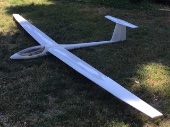
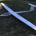
I've been working on a replica of the Sterling Schweizer 1-34 kit from the 70's. I built one their 1-26s from the same era. It wasn't easy to build with all of the stringers and curved sheeting. And I don't recall it flying very well. This was back in the 70's when these kits were "new". I got interested in the 1-34 and found the Outerzone plans online. After some study I decided it wouldn't be too hard to build if I made a bunch of modifications based on building sailplane models for many years. It's kind of a standoff scale approach. All shapes and outlines are the same as the Sterling kit (mostly, there are a few variations). I also wanted to build it light, so, most design decisions are in the direction of reducing the weight as much as possible.
-
I think I will start a new build log for the 1-34 pictured above. Look for "Update for 1970s Sterling Schweizer 1-34"
-
I got the bug to build one of these several months ago. I remember them from my earliest glider flying days. I went with the Outerzone plans for the basic outlines of all the components but changed a lot of the construction details. The outerzone plan doesn’t show the formers so I had to estimate those. I wanted it to be lite as possible so I went with a balsa and styrofoam approach. I changed the airfoil also. I’m using an RG 15. It’s almost done. At 42 ozs it has an 11oz/ft^2 loading, heavier than I wanted but acceptable for slope flying which is all I do. I’m planing on posting a full set of construction photos.