PatMc Posted September 13, 2017 Share Posted September 13, 2017 I won the Amigo 2 kit at a model holiday week auction about 20 years ago (IIRC it cost me £13) but it's been gathering dust ever since. The build eventually got underway in October 2017 albeit at a slow & sporadic rate due to limited spare time. For a 2 metre span glider the box is pretty compact at about 66cm x 24cm x 5cm (25.5” X 9.5” x 2&rdquo. The sheet parts are nearly all die cut, wing and tailplane LE & TE are part shaped. All parts are identified in the plan and instructions by number in the order that the build is intended to be followed. The supplied documentation is fairly extensive – the plan shows the model in it’s free flight form but a full size overlay sheet of suggested RC gear layout with German text is also included together with a separate multi language booklet. There are 2 of A5 size building instruction booklets, one multi language text only, the other in German with illustrations. The actual instructions are quite terse but an A4 size exploded drawing centre spread in the illustrated booklet showing all the numbered parts is a helpful reference. I'm building in a few modifications including an electric motor in the nose plus bolt on wings & tailplane. Originally I'd planned to fit spoilers but decided against them during the build in order to speed things up a bit. IMO they're not really necessary in such a relatively small glider, although it shouldn't be too difficult to retro-fit them at a later date. Quote Link to comment Share on other sites More sharing options...
PatMc Posted September 13, 2017 Author Share Posted September 13, 2017 First problem to sort out was how the motor would be mounted. The build instructions show an optional pylon mount suitable for 049 – 09 engines that Graupner used to make but I didn’t fancy an electric version of that – draggy & ugly. It had to be a nose mounted motor or I’d make it as a light wind slope soarer. The Amigo has quite a deep but narrow nose & I didn’t want to completely spoil it’s lines. I decided to use a 28mm dia outrunner with a suitable spinner so between opening the box and squirting the first glue I spent some time doodling to try and reach an acceptable compromise. Not being CAD savvy I scanned the plan nose area, a drawing of the motor and spinner and played around with them in Paint Shop Pro. Looking at the plan view the parallel section of the fuselage has been extended forwards so that the curve of the nose is 40mm wide at the rear of the spinner. In side view the top curve has hardly been altered the bottom curve has a step in my drawing but this will be sanded to blend with the spinner. A hatch will extend from just behind the motor to the front of the canopy, allowing access to the motor, esc & battery. The designed nose shape. Modified for 28mm dia electric motor. Quote Link to comment Share on other sites More sharing options...
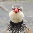
PatMc Posted September 13, 2017 Author Share Posted September 13, 2017 The nose section [pod] build underway. Splicing the boom sheet parts. Boom, boom. Pod & boom - nearly. Quote Link to comment Share on other sites More sharing options...
Tom Thomas Posted September 14, 2017 Share Posted September 14, 2017 Looking very good! Nice looking model pat. Brilliant that you decided to build her, I want to pop e leccy motor in my Sunduster but have no idea of the type of motor, ESC or lipo any advice you could give me? Quote Link to comment Share on other sites More sharing options...
Martin Harris - Moderator Posted September 14, 2017 Share Posted September 14, 2017 Brings back memories of full throttle (had to be as it was on a 2 channel Sanwa transmitter) touch and goes with a Cox .049 pylon engined version back in the mid 70s. Just don't bungee it on a windy day...you probably won't need to ask why I'm sharing that advice! Quote Link to comment Share on other sites More sharing options...
PatMc Posted September 14, 2017 Author Share Posted September 14, 2017 Posted by Tom Thomas 2 on 14/09/2017 00:07:29: Looking very good! Nice looking model pat. Brilliant that you decided to build her, I want to pop e leccy motor in my Sunduster but have no idea of the type of motor, ESC or lipo any advice you could give me? Tom, what wingspan, wing area & expected weight etc is the Sunduster ? Quote Link to comment Share on other sites More sharing options...
PatMc Posted September 14, 2017 Author Share Posted September 14, 2017 Assembly of the front section of the fuselage (pod) was straightforward, the first two formers replaced by wider versions and the base plate altered to give the modified nose shape. Not shown in the pics but I actually held the keel in my Workmate & assembled the base and formers onto this first. When this was dry the side parts were glued & clamped up. The keel in the kit is die-cut 1.5mm ply, I glued soft 3/16” balsa either side of it to stiffen it up but mainly to provide some glueing area for the bottom sheet at a later stage. The longerons, top, bottom and sides of the boom section all required splicing as they would have been too long to fit in the box in single lengths. I decided to cut new full length longerons from my stock wood rather than try to cut accurate splices in these parts (the supplied wood went into my stock box). I was a little disappointed with the inaccuracy of the die cut splice angles of the sheet parts. It would have been better if these parts had been a little over length with the splice angle marked but not cut. Once the boom was complete except for the side sheets it was joined to the basic pod assembly. The two structures were lined up inverted on a fuselage jig and blocked at intervals to give the correct wing and tail incidences. This was left overnight for the glue to dry with weights along the under-surfaces. Next a dry assembly of the tailplane parts revealed that many of the ribs were either over or under length. I was already irritated by the seemingly unnecessary overcomplicated design of the fuselage and a number of inaccuracies in it’s diecut parts so considered making the tailplane as a simple flat plate rather than try to do anything with the existing ribs. It also occurred to me that there might be similar problems with the wing ribs, particularly the tapered tips. With that thought I purchased a set of wing and tail ribs set from iGull Laser I just had a look on Ebay & discovered this , I wish I'd just copied the plan & sold the unstarted kit. In the meantime I made up the fin & rudder with a bespoke horn. Note fin & rudder are bevelled on the left side only, hinging will be on the right side. Quote Link to comment Share on other sites More sharing options...
Denis Watkins Posted September 15, 2017 Share Posted September 15, 2017 The guy on eBay has hit the 9 key too many times Pat, it is easily done when entering details. Am following your build with interest Quote Link to comment Share on other sites More sharing options...
Charles Smitheman Posted September 15, 2017 Share Posted September 15, 2017 This brings back many memories. Keep up the good work. Quote Link to comment Share on other sites More sharing options...
ken anderson. Posted September 15, 2017 Share Posted September 15, 2017 nice model and build there Pat.....I think you may be ahead of yourself with your opening post...you mention that the model got underway in October 17 ? ken Anderson...ne...1...back to the future dept. Quote Link to comment Share on other sites More sharing options...
PatMc Posted September 15, 2017 Author Share Posted September 15, 2017 It was a typo Ken, I meant October 1917. On to the build ... The “V” underside of the pod has 2 skins of 1/16” balsa but the inner skins are only supposed to be glued to the keel & the bottom edge of the (inner) side skin. As mentioned previously I’d already glued some soft 3/16” balsa to the keel to provide some extra glue area, I did the same on the edge of the side skins, trimmed the “V” formers to suit then sanded the 3/16” balsa to profile. The sides of the boom & the inner “V” skins were then glued in place. For the power I decided on a Keda 2217/16 motor which is slightly longer than in the modified nose drawing. It’s 1050 Kv rated (but 1132Kv measured). A couple of quick check first with a Graupner 8x4.5 on 3s : 10.5A for 124W @ 11400rpm. Next with a 9x5 : 14A 165W @ 10000. The motor is rated to 23A max so depending on the model’s finished weight I may use a 10” prop. The motor housing is a lamination of 2 x 3/8” balsa drilled to give clearance with a ply disc spacer glued into the front end, an epoxy board 40mm disc will be cyanoed to that at a later stage. The disc was cut from 1.5mm epoxy board using a 42mm hole saw (Aldi cheapo) then drilled for the fixing screws & ventilation holes. The ply spacer was similarly cut from 3mm ply but IIRC using a 38 mm hole saw. The slightly oversize disc was fixed to a bolt & turned it down to size using a drill & sandpaper. The outer skins either side of the “V” underside are meant to be bevelled then butt joined on these bevels with the joint exactly on the keel line. I decided it would be easier glue one side down first leaving it oversize, sand the edge level with the first skin of the other side then glue down the other side outer skin overlapping this. Sanding the excess down level should, with a little care, get the apex of the “V” nicely on the keel line. To ensure that the outer skins stuck evenly to the first skins I split them lengthwise into three parts before gluing them in place. Each side was left overnight to dry. Once all dry the overlapping wood was sanded flush with the vertical sides. The step fillet block was roughly shaped it and the outer side skins were glued in place. Again one side at a time & left overnight but this time clamped and weighted down instead of being pinned. I built the tailplane using the iGull ribs modifying it with a balsa infill “hardpoint” to take a 3mm nylon screw near the TE & a hook made from epoxy board was cyanoed to the underside behind the LE. A piece of epoxy board notched in the centre was cyanoed under the upper longerons to take the tailplane’s hook, a piece of copper clad board (PCB) with a 3mm nut solder to it’s centre cyanoed under the longerons to take the retaining screw. Once that lot was dry it was sanded & put aside whilst I started on the wings. Quote Link to comment Share on other sites More sharing options...
Tom Thomas Posted September 15, 2017 Share Posted September 15, 2017 A lot of detailed work gone into that pat, looking great, what's epoxy board by the way? Quote Link to comment Share on other sites More sharing options...
Martin Harris - Moderator Posted September 15, 2017 Share Posted September 15, 2017 Posted by PatMc on 15/09/2017 23:04:22: It was a typo Ken, I meant October 1917. Strewth - and we take the whatsit out of a club member who started building a P40 in 2001 (still to be completed)! Quote Link to comment Share on other sites More sharing options...
Geoff S Posted September 16, 2017 Share Posted September 16, 2017 Posted by Tom Thomas 2 on 15/09/2017 23:48:09: A lot of detailed work gone into that pat, looking great, what's epoxy board by the way? It's the board used for printed circuits. It's made from fibre glass reinforced epoxy. I often use bits of old printed circuit board I rescued from the rubbish bins when I was gainfully employed. Geoff Quote Link to comment Share on other sites More sharing options...
Tom Thomas Posted September 16, 2017 Share Posted September 16, 2017 Ah, thanks Geoff! Quote Link to comment Share on other sites More sharing options...
PatMc Posted September 16, 2017 Author Share Posted September 16, 2017 Have now stuck the wing bits together using the ribs from iGull. [I’ll probably use the kit ribs for a simpler version Amigo at a later date] The build was fairly straightforward, with a few minor but annoying niggles. The ply inner dihedral template & the ply outer dihedral braces didn’t match the plan & the spars were oversize in depth [better than undersize I suppose] so all the rib slots needed to be deepened to accommodate them. Strangely, the second from tip rib doesn’t follow the correct taper profile from the spar forwards, despite being exactly as per plan. I didn’t appreciate this until I came to sand the LE, though perhaps I should. It means that the LE sheet doesn’t touch this rib from just in front of the spar – not a big issue as the ribs are quite closely spaced anyway. I fitted spar webs between all ribs instead of just the ones shown, vertical grain for the inner panels. Also added block balsa between the two inner ply ribs to take the wing retaining pegs at the front & as hard points for the screws at rear with ply patches let into the upper sheet covering. The peg & screw retention makes the designed incidence keeper pegs redundant so I missed off the rear one entirely but fitted brass tubes through the added front balsa block to take a suitably bent piano wire dowel between the two inner ribs. Although I’d already decided against fitting spoilers I drilled the inner ribs & fitted drinking straw tubes to route servo wires in case I decide to retro fit them. Other mod included – for the tip dihedral webs cut to shape from 5mm ply to fit between the spars & doubling up the ribs at the dihedral break in order to make the covering a little easier (I always have problems covering neatly at this point in polyhedral wings). Wing LE sheet, tips & a few odds & ends added. Wings & tail nearly ready for covering which will be tissue over doculam. Edited By PatMc on 16/09/2017 23:24:59 Quote Link to comment Share on other sites More sharing options...
PatMc Posted September 17, 2017 Author Share Posted September 17, 2017 Nose job now. Shaped the nose & made up the cabin area hatch cover. The motor was wrapped in cling film & screwed it to the epoxy mount plate to hold it temporarily in place whilst the nose was carve & sanded to shape. I omitted one nose area former as it would limit the battery/esc space & isn’t really needed. The wood used for the hatch cover was mainly stuff from cheapo odd size balsa bundles.The most suitable pieces selected were sanded flat where necessary & a few minutes with the bandsaw got them roughly to shape, finally planed & sanded it all to the desired profile. Hatch cover retention is a button magnet at the rear & a bit of epoxy board at the front. A piece of tinplate cut, bent & cyanoed to a cross-piece provides the attraction. I’ve been a little concerned that the carved balsa nose block doesn’t offer much area for the adhesive holding the motor mount disc in place. The adhesive area is increased by the ply spacer which is a good tight fit in the nose block but although this is glued in place with Titebond it is only 1/8” ply held by it’s perimeter edge. Also I’d initially intended to use medium cyano to fix the disc but realised that lining up fixing screw holes of the motor & mount would be impractical without some re-positioning ability. I decided that the best alternative adhesive would be slow or medium setting epoxy. However it doesn’t penetrate the surface of balsa very well so I drilled a series of 1mm holes through the mount disc into the balsa nose block. I also mixed glass micro fibres into the epoxy. The result is hopefully as effective as a series of rivets supplementing the adhesion. Got the fin fixed in place with the servos & rudder temporarily fitted. Just needs a pair of Bowden cables to be prepared & fixed to finalise the direction control setup. Just needs a pair of Bowden cables to be prepared & fixed to finalise the direction control setup. So far the weigh in of the virtually finished (but uncovered) airframe including the motor, servos, esc & 3s 1500 lipo is 680g (24oz). The Rx plus bowden cable will add about 35g (1.25oz), not sure how much the tissue over laminating film will add. I’ll be happy with a RTF weight up to around 1kg (35oz) giving 9oz/sq ft wing loading. Quote Link to comment Share on other sites More sharing options...
PatMc Posted September 17, 2017 Author Share Posted September 17, 2017 Took some pics of the assembled bare bones before I got coerced into gardening chores. A few time consuming niggly bits to do next before the cover up commences. Quote Link to comment Share on other sites More sharing options...
john stones 1 - Moderator Posted September 17, 2017 Share Posted September 17, 2017 Very nice build Pat and something different. Quote Link to comment Share on other sites More sharing options...
onetenor Posted September 17, 2017 Share Posted September 17, 2017 Looks terrific .Should fly well .All the best for the maiden Quote Link to comment Share on other sites More sharing options...
Tom Thomas Posted September 17, 2017 Share Posted September 17, 2017 Wish my builds were that tidy! Quote Link to comment Share on other sites More sharing options...
PatMc Posted September 17, 2017 Author Share Posted September 17, 2017 Thanks all, for the encouraging comments, much appreciated Work on the Amigo progressed sporadically over a few weeks. This is where I got up to in July. The servos & bowden outers are installed & the inner cables prepared. The elevator clevis & rudder piano wire link are silver soldered to the inner cable. The flappy bits have been hinged & servos fixed permanently in place. The ESC is going to live under a false lite-ply floor that the battery will sit on. Since this pic was taken the floor has had a series of holes cut in it for ventilation and the connector has been changed from an XT60 to XT30. I’ve had to splice some fresh wood into several parts of the wing TE’s as I had sanded them down a bit too enthusiastically weakening the edges which were then getting frayed with normal handling. Once the new wood was inserted & (carefully) sanded I ironed a strips of doculam round the extreme TE to protect them. The whole model has now been covered with doculam ready for a layer of tissue. When it’s assembled in this state it looks no different from the bare bones pics in my previous post. Another snag appeared, I opened the only tin of dope I have only to find that it’s not as colourless as it should be. It’s about the same amber shade as best bitter! I’m not sure if it’s because there’s been some evaporation since it was last used (a couple of years ago) or if metal of the tin has caused some discolouration. Either way I’ll thin the dope then test cover a bit of old airframe with some white tissue & see what results. I’ve got a tin of banana oil that’s also not crystal clear though not as dark as the dope - a sort of lager shade – I might give that a test as well. I really don’t want to have to buy fresh dope as apart from the unwelcome extra expense it would have to be mail order & I’m not sure where I can get it from. Meanwhile I decided to change my original choice of tissue colour scheme using Modelspan tissue that I already have, so ordered some new Esaki tissue from Mike Woodhouse at Freeflight Supplies. Edited By PatMc on 17/09/2017 22:48:51 Quote Link to comment Share on other sites More sharing options...
Tom Thomas Posted September 18, 2017 Share Posted September 18, 2017 I have a mid size tin of red, came to me in a job lot last year. It's old but seems ok. Only a few mm's used, if you could use it P.M me pat. Quote Link to comment Share on other sites More sharing options...
PatMc Posted September 21, 2017 Author Share Posted September 21, 2017 Thanks for the offer, Tom but I’ve already done the test piece which seemed OK so I thinned the dope & went ahead. The wings & tailplane were covered using [not so] clear dope but for the fuselage I used Wilko’s clear satin water based varnish. The white & black tissue used is heavyweight Modelspan, the red is Esaki Super Flite. I chose to cover it with tissue in an attempt to preserve it’s 1966 vintage appearance as I’ve seen a couple of Amigos covered with Solarfilm that just didn’t look right. As it is it’s a bit of a “Plain Jane” [or should that be “Plane Jane” ?], once it’s flight trimmed I’ll add some décor. Checking the cg on my patent balance weight measurer I found that it’s nose heavy, requiring 16g in the tail fairing to achieve the plan CG. The plan cg is very rearward at 55% of the wing chord, which wasn’t uncommon common with basically free flight models of the Amigo’s era especially given it’s generous tailplane area & longish fuselage. I decided to do the first few flights without adding any tail weight. RTF weight with a 3s 1400 lipo comes out at 932g without the tail weight. Current draw with a 9x5 prop is 14A, power 165W. I was hoping to maiden it at my local slope to suss out the trim before flying it on the flat but the weather wouldn’t co-operate so did the maiden in stronger than ideal wind conditions at the club field a couple of days ago. Climb & glide were reasonable without any change in trim being necessary. I found I could hover flying directly into wind but only needed a touch of down to pick up speed quite well. Next flights will be with an altimeter on board & the power will be cut at 30secs to assess the climb performance. I did do a hatcam video of the flight but the camera wasn’t lined up very well & the model’s out of frame most of the time so not worth posting. Quote Link to comment Share on other sites More sharing options...
Tom Thomas Posted September 22, 2017 Share Posted September 22, 2017 Wow! Great read pat, brilliant that you've Maidened it and it performed so well Looks great too, is using dope and tissue cheaper than film? And how did you use the doculam and then the tissue over it? Only time I ever used dope and tissue was back when I was about 14 and used it on a small free flight glider, but I remember nothing about how I did it Anyway great job on the build and the maiden Quote Link to comment Share on other sites More sharing options...

Recommended Posts
Join the conversation
You can post now and register later. If you have an account, sign in now to post with your account.
Note: Your post will require moderator approval before it will be visible.