

David P Williams
-
Posts
1,490 -
Joined
-
Last visited
-
Days Won
2
Content Type
Profiles
Forums
Blogs
Gallery
Calendar
Downloads
Posts posted by David P Williams
-
-
Paul - grease will pick up dust and grit from your field and turn into grinding paste.
-
Yes Dick, me too. Electronickery baffles me, I thought 555 were cigarettes years ago.
Thanks for the input everyone. I’m as sure as I can be that there is no binding, they are wire legs and the wheels are not too heavy. The battery is buried under the fuel tank and if I change it to a four cell I’ll need to go upon the church roof again.
So - I think I’ll stick with the five cell and either a second smaller 4.8v pack for the retracts (lose some lead!) or a diode in the retract feed.It’s a VQ ARTF and heavy and a bit naff generally, but I picked it up cheaply to use the 91fs I had lying around, so if I get a few flights out of it I’ll be happy.
-
The servo is now out of the model, I’ve taken the bottom of the case off and had a good look around the wiring and circuit board and there’s no sign of burning anywhere.
It is now totally unresponsive using a servo tester and regulated supply, both 5v and 6V. The replacement servo works fine with the tester.
-
I've just put together an ARTF model using Savox 0351 servos with a Hitec HS75BB retract servo for the mechanical retracts. All of these are rated for 4.8V or 6V operation. I usually power model radio gear with a 2 cell LiFe with no problems but I needed a fair bit of weight up front so I decided to use a '6V' 5 cell sub-C NiMh pack.
I did the bench setup with the pack as delivered which showed about 6.25V on my battery tester. All worked fine, the mechanical retracts worked perfectly with no binding at all.
I charged the pack, noted it topped off at about 7.25V, and set off to the field for first flights. The model was transported wheels up, so when assembled I powered up and selected gear down - all OK. Range checks, engine setup, etc then first flight. A few circuits, trims sorted, so selected gear up. Flew by and saw the gear was still down. tried cycling to no effect so left selected down. When I came in to land the gear just collapsed, obviously not locked down. The retract servo was totally unresponsive.
Back on the bench, checked all connections, still dead. Tried it on a 5V regulated supply, still dead.
So - I guess I've cooked it. I have another HS75BB but I obviously need to do something about powering it differently before I fry that too. I know I can use a separate battery for the retracts (and I know it's good practice to do so) but would the trick of adding a diode in the retract power supply drop the 5 cell NiMh voltage enough to keep the servo happy? Maybe two diodes in series?
-
But that’s not Weston though is it, tarmac and a control tower. Weston’s just a big park.
-
 1
1
-
-
Thanks for the prompt Chris - I remembered that I had found, years ago, somewhere in the depths of the internet, a copy of the DeHavilland Care and Service Manual for the DH89a. A quick rummage in my old desktop computer and I found the control movements for the full size aircraft.

This may help, but of course full size doesn't always translate directly to model size.
-
Hi James,
I have the Jerry Bates plan and also the Martin Tuck plan at the same scale but no clues on either. Have you tried contacting Jerry himself via his website? Click here
-
The article to which the OP refers (and I have just read) is about the possibility of mobile phones corrupting TX (and RX) software by electromagnetic swamping, and the OP was questioning how this relates, if at all, to WiFi updating of the TX.
-
You would also be surprised how small the wing attachment bolts are on the full size -a couple of 1/4” diameter bolts for each wing half and the same for the struts IIRC.
-
1
-
-
No pawls or ratchets, these are used a lot in model helicopters for autorotation freewheels.
-
2
-
 1
1
-
-
SLEC sell balsa in 48”, 1220mm lengths, I buy that. Four blades easy.
-
I have the same two-stage flap settings as the full size - 15deg and 30deg - and they work just fine. No elevator compensation needed as Tim says.
Good luck with the maiden, they do fly nicely.
-
I did some digging too - early J1s had Cirrus engines, exhaust port side. Later ones had Gypsy Majors, exhaust starboard side. Depends exactly which version you are modelling it seems
-
Are you sure it’s on the wrong side Danny? I thought Gypsy Major induction and exhaust were both on the starboard side
-
Haven’t seen a Storch up close but other full size aircraft I’ve seen with those type of hinges have had slots to clear the hinges
-
David - you don’t want to do the test, you don’t need to do the test, so just carry on enjoying the flying that you do.
-
3
-
-
Mine appears and disappears all the time, particularly in relation to repairs and maintenance rather than new builds. It usually vanishes for long periods when a model gets to the painting/finishing stage.
My current big project was started at the beginning of the first lockdown and I thought it would take six months, but here we are almost two years later and halfway through covering. Just the dreaded painting to do.
-
My wife is an artist, so I have access to oils (when she’s out) and I think they would be ok for a pilot in an enclosed cockpit, but they take forever to dry so I’m not sure how good they’d be for my open cockpit application. I’ll do some test pieces and see how it goes.
She’s a very competent portrait painter, but I can’t talk her into painting pilots for me unfortunately.
-
 1
1
-
-
Danny I did find this, not sure about the colours but the principles look useful.
-
I’d be interested in that too - I’m also approaching the point where I’ll have to paint mine and previous efforts have not been great.
-
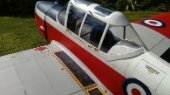
Well, another six months has gone by with little work on the Stearman. I must be heading for a longest build prize. I had a big loss of confidence in my ability to complete this to a good standard and even contemplated selling it as a project, but I've given myself a stern talking to and now I'm trying to devote some serious time and effort to it in order to have it ready for outdoor spraying when the weather improves, and ready for flying this summer.
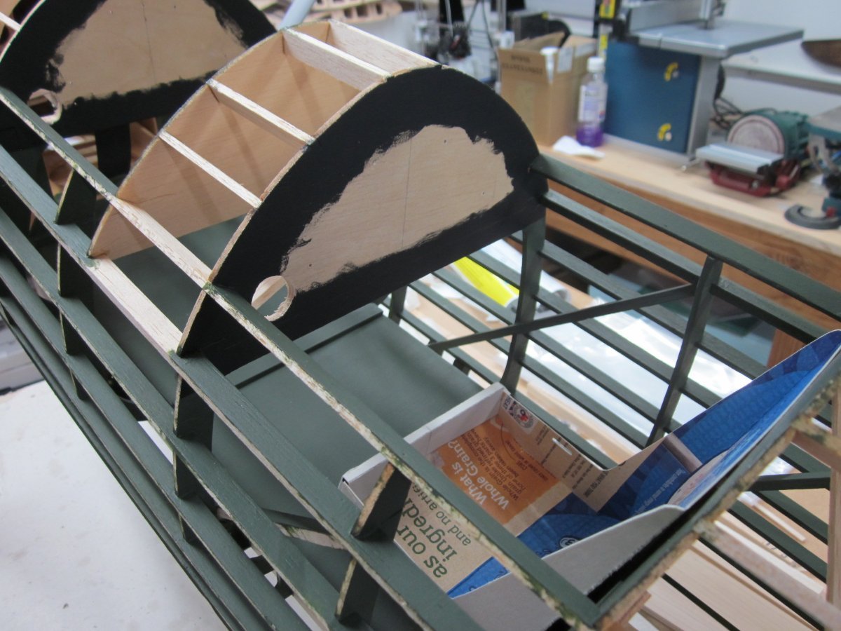
So - here's where I'm up to. I needed to paint the cockpit interiors while I still had relatively easy access before covering and panelling. I also needed to work out and fit cockpit flooring to cover up the radio kit and batteries etc., instrument panels, pilot's seats and of course pilot figure or figures. All of this was easier before covering as I can get fingers between longerons and also see and measure from all round. There has been much headscratching and not much actual doing, but I'm finally making progress.
Usual use of cereal packet to work out size and shape of seat.
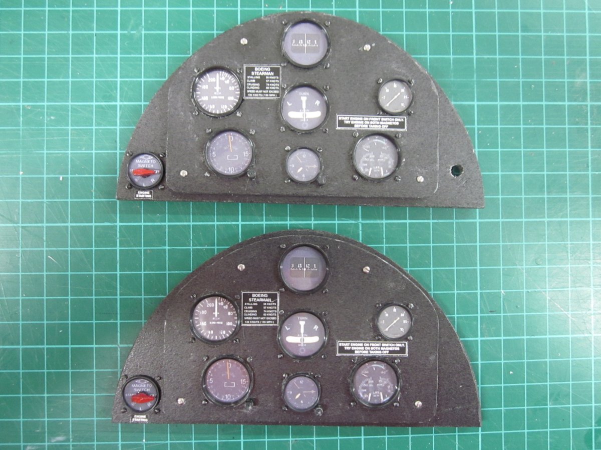
Panels based on instrument sets from Aerocockpit, but instrument faces replaced with slightly more accurate 1930's US ones - mph and feet not knots or meters.
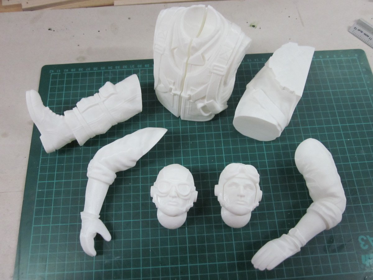
The Stearman is probably going to be finished as a US Navy N2S, so trying to find suitable pilot figures was difficult. They either look cartoonish, or British, or £120 each. I found some beautifully sculpted figures for 3D printing via Thingiverse. They are not free downloads, they are commercial offerings from Max Grueter and cost me $39 for the files. As supplied they are 1/6 scale, but are easily scaled in Cura when loading for slicing. Although the Stearman is referred to as 1/4 scale it is in fact 1/4.3, so after wrestling with the maths I needed to scale them up by 139.5%.
Of course that meant that the main body component was too large to fit on the bed of my rattly old Anet A8 3D printer, and anyway it looked like a 2 day print and I don't like leaving the printer running unattended for long periods.
Forunately, when my copy of Fusion360 upgraded itself to the latest version, it now includes some pretty good mesh editing facilities, so I was able to divide the main body into four components initially, then six to keep the print times down. I now have right and left pilot's arms, right and left gunner's arms (these may work for the instructor figure), right and left torso, right and left thighs, right and left knees and goggled and open face heads. They should all glue together OK. Still experimenting with Cura settings, but so far I have these.
Not looking forward to the painting stage.
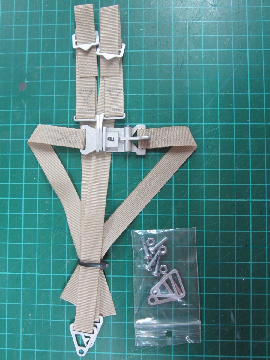
I also cheated by buying seatbelts from Aerocockpit rather than messing making them from tape and lithoplate.
The finale time consuming job has been sorting out the vac formed wheel hub covers. These didn't fit the supplied wheels, so I ended up turning spacer rings to look like aluminium wheel hubs (you can just see them in the pic) that had the correct sized recess for the hub covers.
My intention is to not have switches but to remove one or both floor panel/seat/pilot units to directly plug or unplug flight and onboard glow batteries and also to remove the batteries for charging. Trying to work out if this will work by measuring with bits of wood and string is hopeless, so next steps are finishing at least one pilot figure to finalise the seat size and shape and making sure that when fitted to the removable floor panels that can still be fitted and removed without fouling anything.
After all that I can move on to covering.
-
4
-
-
My full size exploits were over 15 years ago now so I can’t remember for sure where we sourced the screens, but probably here. A mere £1600.
The open cockpit build is a Stearman, getting back to it after a long layoff and will be updating my build log in the next few days.
-
1
-
-
When I worked on full sized vintage aircraft I fitted several replacement screens on Austers. No idea how the replacements were made, but they arrived ready formed, mostly fairly accurately, and an inch or two oversize all round.
No-one else wanted the job of trimming and drilling the holes for mounting screws as they thought they would crack or split the very expensive screen, so the job always fell to me. It would take ages, trimming tiny bits off at a time, and as you say Danny, trim one bit and it messes up another.Really enjoying following the build by the way. I’m building something different but have also just spent several days on instrument panels - it has two, and open cockpits, so they have to look reasonable.
-
1
-
-
Balsa Cabin list Blue Foam sheets, although the description changes to ‘Grey Styrofoam’ when you click on the actual item. 50mm and 75mm thick sheets in various sizes, looks just like the Blue Foam I still have left.
-
1
-


What's flying over your house
in Full Size Aviation
Posted
When I worked at Spanhoe airfield we had a Gemini based there. It had been obtained in a part exchange deal and was on the Belgian register (OO-RLD I think). Lovely old aircraft, flew in it quite a few times.
When I was 15, well against the run of form, I won the form prize at school, and the guest speaker at Speech Day who presented the prizes was Douglas Bader, so I got to shake the great man’s hand.
Like many very successful men he was quite brusque and arrogant, not quite as portrayed by Kenneth More.