


reg shaw
-
Posts
1,203 -
Joined
-
Last visited
Content Type
Profiles
Forums
Blogs
Gallery
Calendar
Downloads
Posts posted by reg shaw
-
-
Loving this topic, but how heavy is the model going to be, up to 45kg!!!!??? A Halifax is similar in size to a Lancaster (I obviously could google!!) so 1/9th scale is about 11.5 feet or so isn't it? This model will be nothing like that weight unless something has gone badly wrong. Is there a thread on the build of the model anywhere. It shouldn't need to come out a right lot over 20kg at worst. Here's hoping there's some typo's here, kg instead of lb for example?
Lovely to see and keep up the splendid work!
Ian.
-
I like threads like this as it shows I'm fairly normal! Have a few new builds, a few refurbs and a couple of kits to keep me going, when I get the time to find the enthusiasm!
new builds
1/4 scale Boulton Paul Defiant
1/3 scale Albatros DVa
1/3 scale Roland C.II Walfisch
1/3 scale Minimoa 2a two seater
1/3 scale Grunau Baby
1/2 scale Druine Turbulent
Refurb projects, either old models or ones acquired as projects
1/4 scale Vickers Wellington
1/4 scale Polikarpov I16 Rata
1/3 scale Sorrell Hiperbipe
1/3 scale L4 Cub
1/3 scale Supercub
2/5 scale As K8b sailplane
1/2 scale Stits Skybaby
Kits
1/2 scale Fournier RF4d
1/3 scale Pfalz DXII
plus a few indoor scale kits for rubber and or radio.
Flyable
1/2 scale Flying Flea
1/3 scale Sopwith Pup, should be in projects as I had a mid air with it a month or two ago.
1/8 scale Handley Page HP42
1/4 scale Mitsubishi Zero
1/7 scale Junkers Ju52M
Jiant Jabberwok
plus a few other bits of projects etc, whether I do them or not, they're not coming to harm, there's no rush!!
-
That looks more like a Dennis Bryant Storch. He does two sizes, 70" and 92" The cockpit structure on the Svenson one is mainly plywood, yours looks to have piano wire for some of it, like the Bryant design. Looks like it could be a great model once again!
Ian.
-
Hi Eric, you could use a sacrificial plate for fine work on your scroll saw. I use 3mm MDF normally. Simply cut a bit that is a bit smaller than the bed of the saw, then saw into it until it the MDF sits on the bed evenly and tape it to the bed. No gaps around the blade for small bits to fall down. Hope this helps, Ian.
-
The slats are definitely fixed on the Storch Eric so you could save yourself a couple of servo's. The chain and linkage on the port cabin side is for the flaps, which are interconnected with the ailerons to droop the aileron when the flap travels past about 20 degrees IIRC I'd love to see the set up for the slats on the model, do they push forward or roll forward to open them? Any images you could share from the manual?
Many thanks, Ian.
-
Why 6 servo's in the wing? Aileron and flap each side, what else moves? Have the manufacturers made the slats move too, unlike the real Fieseler Storch?
Looks like a decent enough kit, watching with interest.
Ian.
-
Quality job. This might possibly be the first model An2 to fly at anything like scale speeds! Will it have a mass of flappery Simon?
How many printers have you worn out up to now?!!
Ian.
-
He'll not want the item now he know's you'd ignored him though!
Edited By reg shaw on 05/01/2019 15:07:43
-
There seems to have been a few nice warbirds posted recently, so I went rooting amongst my pics. I don't have any glow motors anymore, let alone Lasers, but eagerly await the introduction of Laser petrols. Here's an old one of a 1/5 scale Bf109 E-4 in Gallands colours. Powered by an ancient, even then, Laser 150V. It needed onboard glow to keep one of the two fires lit but sounded fantastic as it would reliably cough and fart on one but would always come back in. It was fully enclosed, rockers removed and the last exhaust stub each side was the Laser exhaust, the other 5 each side was cooling air out. I really tried to go to town on this one, working auto slats, radiator shutters and the canopy and its windows opened. I'm going to root some more as I've done a few Laser powered models over the years. How soon til the petrols are here (tongue in cheek!! When they ready, they ready!!)
Ian.


-
The Be2 was a sort of replica built using Tiger Moth parts, it still is airworthy today flown by Matthew Boddington. They built a Sopwith Pup for ground shots. A couple of mates and I restored it down at Stow Maries where it has now been joined by some other WWI aeroplanes from the Vintage Aviator in New Zealand. If you look closely you can make out a miniature Mr Poyser in the cockpit! I never did get it started!
Ian.


-
Memories aye Geoff, very pleasant ones for me!! Timo, you are certainly right with the design of these little full size wooden aeroplanes, so much can be copied straight off into our model designs. Regarding the Fournier RF4, they must be amongst the most graceful and aerobatic aeroplanes of all time, and all on a Beetle engine! Here's a pic of my 1/2 scale Fournier, designed totally in CAD, complete with all hinge and linkage mechanisms including the spoilers etc. I hasten to add it wasn't me that did the cad bit, though I was present to point at which bits I wanted where and the thicknesses of materials etc. This too will hopefully go well enough on a Zenoah 80 twin, complete with on board starter this time. It'll have to wait a bit yet though. I took it out of the box to see what else I needed, then in about 10 minutes the fuselage had 'clicked' itself together! All unclicked and back in the box again now. It spans out at 5.6 metres give or take.
Ian. ps, you going the indoor do tonight Geoff?

Ian.
-
Posted by Danny Fenton on 14/12/2018 15:22:35:
I do like the way the horns are part of the hinge plate. Making a part serve multiple functions is always sattisfying
Well if it was good enough for Monsieur Druine it'll be good enough for this ickle one.
Ian.
-
Thanks Danny, I'll get there in the end!
-
Nice subject! I love this era of aviation. Are the plans drawn to incorporate the wing fold? Just seems a bit odd to build the wing with the rear spar pre broken! Still plenty of strength due to the struts though.
Ian.
-
Yes Geoff, the plywood wing ribs are lasered by Dylan at Lasercraft as was, the tailplane was lasered by me as its balsa, and the hinge components were cnc routed. I did all the drawing as an exercise to get better at CAD. My next 1/2 scaler is waiting too, a Fournier RF4 which follows similar design to the Turb, I have the bits in waiting!
Ian.
-
Not much time in the den tonight, but the next unknown seems to work alright. Had a bit of a lash up of the aileron hinges. These are cut from g/f circuit board, and follow the scale external dimensions but they don't bolt onto the airframe like the full size, they interlock around the upper and lower spars so are strong and light(ish!) The inner hinge incorporates the horn, which on the full size is closed loop cable actuated. This can be as the top hown is there to run between the hinge plates but I reckon it'll be a pushrod to the bottom I do. We'll see. When the ribs were drawn up, lots of spacer bits and packers were drawn too, so the skin cutouts in the aileron are all supported. This is all just dry assembled and taped where neccesary as the shear webs need shortening accordingly to suit the hinge plates and packers used in each rib bay. I did a vid of the hinge in action, like some of you forum builders do, but it says its too big and saves me the indignity of admitting that Terence Trent Darby was on the radio at the time, oops...


-
The proposed motor is a good old Zenoah 80cc flat twin. It'd be nice to have a flat 4 pot four stroke petrol, though sadly that is financially well and truly not in the picture! A good chunk of the Zenoah should be hidden by the 1500 VW engine though and it'll be well silenced with a stainless canister under the cowling.
Ian.
-
Fairly productive couple of hours, managed to start building two left panels, another with anhedral and one with a shorter aileron, but eventually settled on the right amount of bits in an opposing pair of wing panels!! The bulk of the ribs and shear webs are mounted on the main spars, left off the first two ribs at the moment as I need to drill for the U/C mounting brackets, but need to make them first. I also aint too sure what happens at the rib that sits under the fuselage side yet so will probably leave that until I have a fuselage side for it to sit under, since the curve of the side will govern the position. Its pleasing how square the structure is even though there is so little of it, mainly due to the lasered ribs and the batch produced shear webs. The spar material is cyparis from Solutions, very accurately cut and glues up a treat. I'm using medium cyano for the bulk of the assembly, though the spar stubs and root shear webs were araldite epoxy. Work drew to a halt as I realized I have to machine a quarter round section of the lower rear spar, to form the start of the aileron shroud, and its a tad late to get the router out!
Ian.


-
The wing mainspar centre section has now been completed, with shear webs added to beyond the U/C mounting positions, the simple wing can now be built onto it.


The rib spacing is all the same after the root rib so its a simple case of shear web, rib, shear web, rib etc etc... making sure to add the correct rib and the correct amount as the spars are over long at the minute! The shear webs are abviously all the same width too, just front and rear spar depths to think about. When I drew up the ribs in ProEngineer they were done to allow for the aileron, slot etc so there are quite a few different ribs to pick from when assembling! Full ribs, ribs without a front, ribs with an aileron, ribs with and aileron and a slot.... Lets see what comes out!!


-
Posted by Geoff Sleath on 11/12/2018 11:47:15:
This looks great, Ian. I hope you'll turn up one Wednesday evening with a few pieces for us to admire.
Geoff
Every chance of that Geoff, when's the next one? Mr Poyser Rob Shipton and I were just talking about coming to the next, definitely not for the mince pies though you understand?
Cheers, Ian.
-

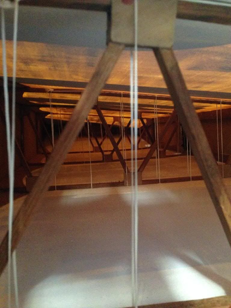
This pic shows the two stubs together. The narrow bit in the middle is where the fuselage box will be. The birch ply plates are at the moment on opposite faces of the spar, ie. one on the front and one on the rear (making a full spar in the fuselage box), but there will be one on each side eventually, but they aren't required at this stage. The U/C mounting brackets are all mounted to this spar, the oleos towards the outer ends of the stubs and the main U/C gubbins further inwards, at the fuselage joint almost, hence the beefy structure around this area.
Edited By reg shaw on 10/12/2018 23:38:43
-
The main stumbling block in this very simple design is the wing join and mounting to the fuselage. The full size has a one piece wing, four bolts hold it on, two through the front spar and two through the rear. There isn't a top skin on the wing in the cockpit area, so all you see is a one piece main spar, and behind it the joystick is bolted down to some timbers on the top of the bottom wing skin.
It would be easy to have a one piece wing and it would be 'manageable', but it would limit what else I could take to fly, a two piece centre join would be next easiest, but the differences in the cockpit would be obvious and I'd have to connect the joystick up every time the model was assembled. Also a centre join would make the underside of thing at that point more difficult to build as the bottom skin 'flows' from side to side, ie, no kink at the dihedral break.
So I decided to make the wings plug in leaving the cockpit area untact when the wings are removed. I've made up the main spar stubs which will now allow the wings to be started. There is a wooden square tube to be made up and built into the fuselage. This has the external dimensions to match the full size spar, the internal dimensions accept the stubs on the wings. These stubs are cut from 9mm beech sheet in the middle, with 6mm birch ply faces on opposing sides of each. The beech component has a fancy cut involved which makes a tapered dovetail joint which when slid together makes a very rigid joint. When combined with the good fit (hopefully !!) in the fuselage box it should take all the loads from flying, landing etc without issue. This little lot was assembled with Araldite and panel pins and cleaned up whilst the glue was still wipable, hence the bloomin' mess!!
Ian.


-
Hopefully this image answers that Geoff. Image from that superb resto thread I linked.
Ian.
-
After a bit of time doing other stuff, I have had a bit of time to do the final bits of research to get the doodles finalised. Lucky for me, G-APNZ is undergoing restoration not too far from me at Derby Aero Club. A phone call and a few emails finally gave me the go ahead to venture over with a tape measure and a camera to discover the differences between this Turb and my initial drawings.
The main differences lie in the top deckings ahead of the cockpit and engine cowling profiles. PNZ has a deeper top deck as it has a long range fuel tank fitted, and the cowlings on Turbulents are different on every one. Indeed this one in it's history has had three or four different profiles fitted, with bumps and bulges to cover extra bits bolted to the 1500 VW Beetle engine.
Derby Aero Club were very accommodating, even giving ME permission to remove the seat structure and refit the engine cowlings for a better look! I took with me a list of all the measurements I wanted, and another list of the images I needed to get, although I promised not to 'publish' too many pictures. I've corrected the drawings and designed an unobtrusive method for 2 piece wings whereas the full size has a one piece wing that the seat base, joystick etc all mount to.
I've had a quick look at the materials needed and I have most of the acres of plywood required for the skinning of fuselage and wing leading edges etc. I have no steel tube though for the U/C yet though, but it'll be a while 'til it needs it's trottery.
Also, found this thread a while ago that has some great detail photographs of a Turbulents innards.
More hopefully sooner than later,
Ian.
Ashbourne Scale Day 2021
in Shows, Club Events and Competitions
Posted
We aren't too strict on noise, any models that aren't deemed quiet enough will be asked to reduce throttle settings, change prop or just fly in the right places. Don't worry unless you know it makes a racket!! We won't have a db monitor on site. Some models that meet the 82db seem far noisier than some that don't. Perceived noise is the key.
It's filling up nicely, cheers folks, Ian.