


Dennis Mulhair
-
Posts
122 -
Joined
-
Last visited
Content Type
Profiles
Forums
Blogs
Gallery
Calendar
Downloads
Posts posted by Dennis Mulhair
-
-
Hello All,
Does anyone know how I can soften/disolve an epoxy resin joint. I need to remove part of a wing that has been joined using epoxy. Also, On the same subject How do I unglue a PVA joint without submerging the job in water for ages?
Hope someone can assist.
Dennis
-
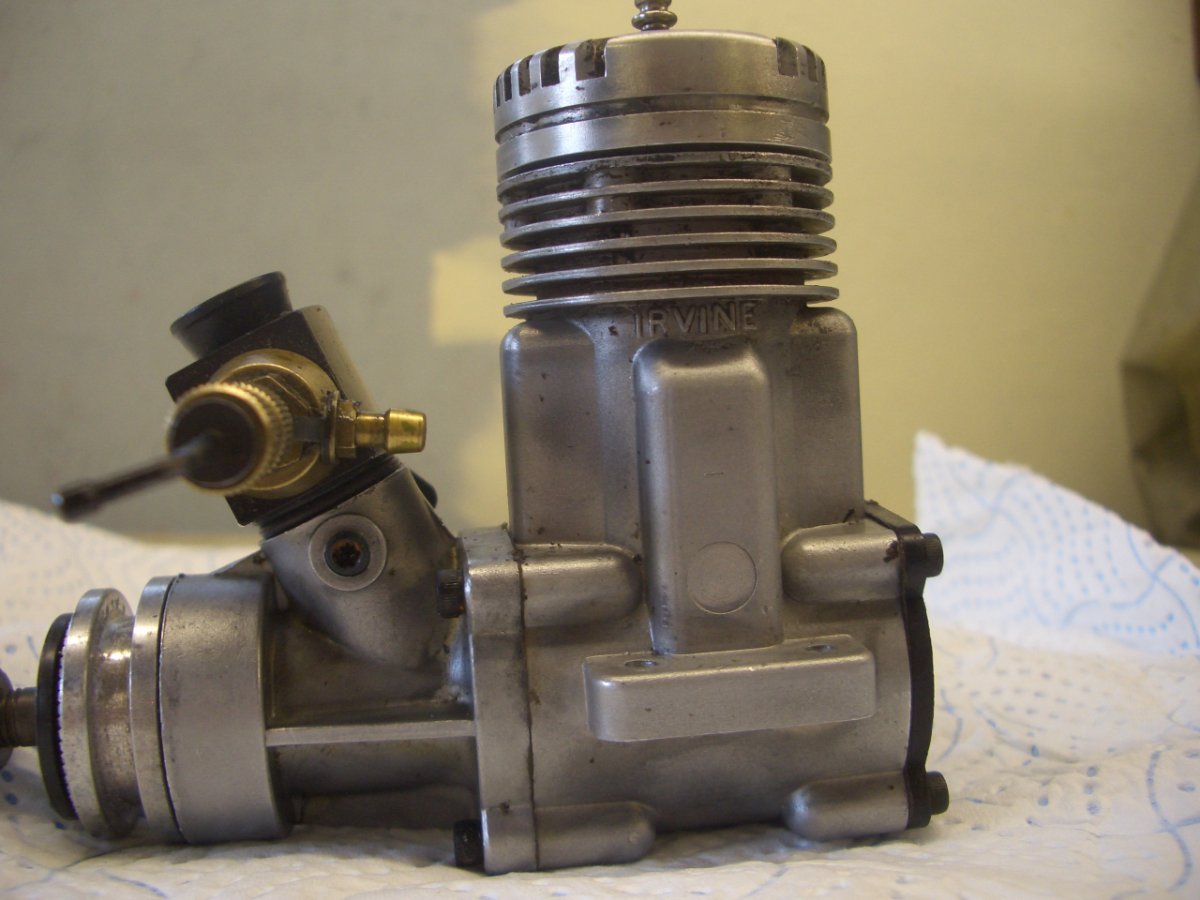
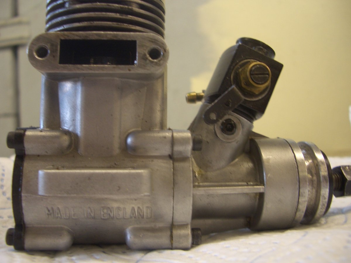
I managed to get some drawings of the Mk2 & 3 motors and the MK3 has the words "IRVINE" vertically written on the crankcase and the screws for the exhaust go through the case into the exhaust pipe. On the MK2 (ABC) "IRVINE" is written directly below the cylinder barrel and the screws do not pass through the crankcase.
So I believe my motor is a MK2. Do you agree?
Dennis

-
Thanks folks for this. Been talking to Wheekspin Models and they contacted the inporters of Irvine engines and they say as long as its an "ABC" then most parts will fit. So Im going to order a new piston & liner and see what happens.
Once again Thanks folks.
Dennis
-
 1
1
-
-
Hello,
Recently I was given an old Irvine 46 motor. I need to get some parts for it but I’m not sure what mark it is. I do know that it was made in England, the Allen screws that hold the silencer on need a 1/8” Allen key and the body is not RED.
Can anyone tell me how I find out it mark No. So I can order the correct parts.
Many Thanks
Dennis Mulhair
-
Thanks Steve,
I have PM'd Ian and waiting for his reply.
Dennis
-
Hello,
I have just acquired a rather dilapidated T180. What are the chances of getting a copy of the building instructions and wing plans? I have tried the link to IanR but it no longer works.
Hope someone can help
Dennis
-
Hi Mike,
Can you confirm please that the latest version of the D8/D4 software is 110420. I take it this will work with the new FRSky XJT software XJT_ACCST.2.1.0
Regards
Dennis
-
Is anyone interested in buying a wattmeter as I have one going spare?
Dennis
-
Then again I suppose if I was measuring in the real world using say a 1 cell LIPO and an actual motor and esc the readings would make more sense. I will try this tomorrow.
Dennis
-
Hi Chris, so if the value is that at "Max Power" maybe the Min Volts & Max amps be relabelled to MPvolts & MPamps? At the moment its a bit confusing.
Dennis
-
Hi Chris, could you explain an anomaly I have come across. I am running the units on V4 software and have noticed the “Min Volts” is recording what appears to be the maximum voltage of the cell. I was expecting the cell voltage to drop in use and with a volt meter across it it does, but the Wattmeter is still recording the higher voltage that was there at switch on. The “volts” value faithfully follows the state of the voltage on the cell.
I replaced the 1 cell with a power supply and the unit was the same. When I lowered the voltage on the supply the wattmeter only recorded the higher initial voltage in “Min Volts”, but if I increase the voltage (something that would not happen in the real world) the “Min Volts” alters to reflect this increase.
Are we recording the Max voltage of the cell, and so should the labelling change to “Max Volts”?
Regards
Dennis
-
Works well and accurate.
-
-
H Chris,
Thats got it. Current readings now matching the digital meter.
Now to fit it in the box.
Dennis
-
Hi Chris
Just gone through the current setup and the unit is reading high, see below
5.54V------- Meter reading 0.530A---------Ardunio reading 0.53/0.58A
7.64V------- Meter reading 0.730A---------Ardunio reading 0.80A
10.26V------- Meter reading 0.991A---------Ardunio reading 1.06
This was with the current pot at its lowest setting. I am going to load your mod above and come back with more results
Dennis
-
Hi Chris,
I’ve noticed occasionally that after switch on I’m getting a white screen, to restore the program I’m having to use the reset button on the Arduino to get the program to start. Have you come across this before?
Dennis
-
The spacing of the table didn't come out as expected when I uploaded it. Example:
Arduino Pin No: =VCC
Motherboard socket pin number: =1
New screen connection: =VCC
-
Hi Chris,
Haven't got that far yet but still making progress. I ordered my screen very early on when Bitsbox didn't have any in stock so got mine from Ebay. As far as I could tell they looked the same as yours but the pcb seems to be bigger as it doesn't fit your box and there are more pinouts on mine!
Finally got it working using the following conversion table
Arduino pin no. motherboard socket pin No. New screen connections
VCC 1 VCC
GND 2 GND
8 3 CS
9 4 RST
10 5 RS
11 6 SDA
13 7 CLK
I am at the stage of setting the input voltage on a 3 decimal place digital multimeter which seems very stable. I'm using a 1 cell lipo to set this, will attempt the current setting tomorrow. Will come back to you with my findings.
Regards
Dennis
-
Hi Chris, The board is built and the Minipro 328 has accepted the sketch so its ready for final testing. Can you please run through how I setup the calibration of the unit using the two trims.
Thanks Dennis
-
Chris, Is the software in the Dropbox contain the latest updates?
Thanks.
Dennis
-
Hi Chris, Just read throught the earlier pages and found the answers to my questions.
Dennis
-
Hi Chris,
Looking at the picture of the assembled circuit board I see you have the Tant 1UF (C2) capacitor in the position of C1. Is this correct? Also, you have the +ve leg of the capacitor connected to P1 terminal of the screen.
-
Nice Chris!
Dennis
-
Hi Chris,
Circiuit board arrived today, just waiting for the display to arrive before I can start building.
Thanks
Dennis


Irvine engine types
in IC Engines
Posted
The Liner is OK nut the piston is scored. Trying to get one now before I can't. Also could do with bearings. As I see it might as well replace these too if I'm taking it all apart.
Dennis