


John Stainforth
-
Posts
755 -
Joined
-
Last visited
-
Days Won
2
Content Type
Profiles
Forums
Blogs
Gallery
Calendar
Downloads
Posts posted by John Stainforth
-
-
3 hours ago, Paul De Tourtoulon said:
No offence taken Jon, but I think that my crashes were due to a bad synchronisation of the engines,,
I don't make pilot errors,,?
Ps, I do put wash out on a lot of my planes for the first flights and limited aileron and elevator throws,,
Wow, you are tempting fate with a comment like that!
-
46 minutes ago, Gordon Whitehead 1 said:
Ethanol has only 60% or so of the calorific value of petrol, so presumably E10 will will deliver a lower mpg and lower top speed than neat petrol and for the same power you'll need a wider throttle opening. Dunno if anyone will notice.
I had a Toyota Prius in the US for 16 years, where they have had E10 for much of that time. Sometimes "gas" stations don't add the ethanol, or forget to add it. (The ethanol is delivered separately there and simply added into the underground petrol tanks at the gas station, in the right proportion.) I watch my mpg all the time and I found that under typical driving conditions my Prius would do 48 mpg (that's miles per US gallon) on petrol without ethanol and about 45 on E10. I could spot the difference between the two fuels after just a few miles of driving. So I think E10 is of very debatable value for the environment, particular when the energy to grow the ethanol crops (corn) is taken into account. In the US, the whole E10 was generally viewed as a subsidy to farmers.
-
 1
1
-
-
The biggest problem when flying models in strong winds is the ground, where they can get blown over hard or off tables etc, if one is not very careful. Once in the air it can be great fun. I particularly like being able to land more or less vertically
-
1 hour ago, EvilC57 said:
Well I have two Permagrit sanding blocks, a Sanding Block, and a Wedge Block . The one I use by far the most is the wedge block, as it’s useful for sanding things at 45 degrees, and unlike the normal sanding block, the cutting surfaces go right up to the end.
I like many of the Permagrit tools, but the one I have used the most is the long, wedge block with coarse/fine grit on the opposite faces; probably followed by the short block. If I had to chose just one, I would go for the long wedge block. (Might as well get the wedge block; I don't see any advantages in the one without the wedge.)
For special applications, I make my own sanders by gluing sandpaper onto strips of wood or cardboard tubes, etc
-
1
-
-
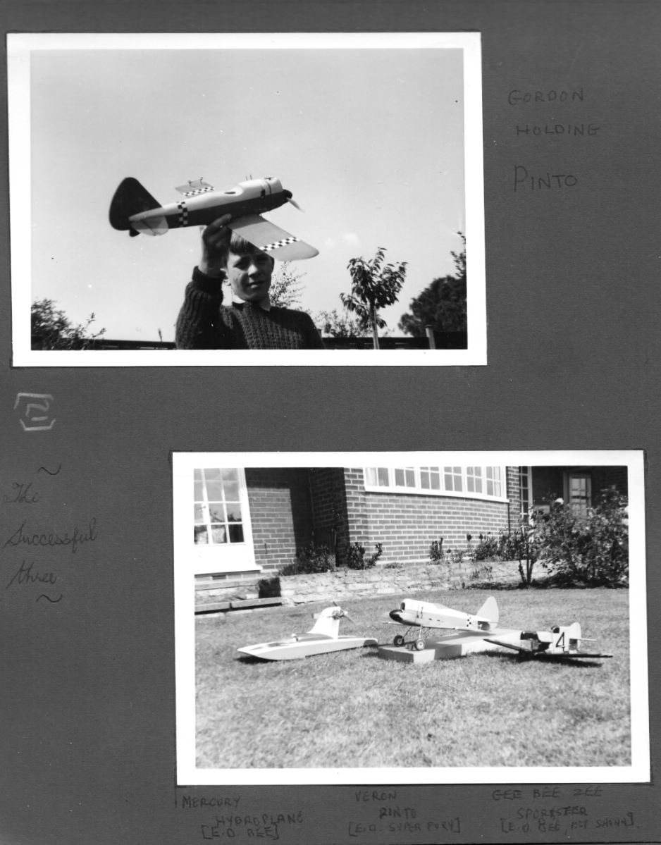
On 31/07/2021 at 09:10, Steve Goodwin said:
Not only are old photos special, it’s the comments that evoke memories too, I love the comment “the successful three” which suggests to the reader that there were others maybe not so successful!
I can't remember all the unsuccessful ones, only that they had violent confrontations with the ground!
-
Rich,
You are not thinking of the Veron Pinto by any chance, are you? My brother and I had one of those in 1963, powered by an ED Super Fury:

-
If it's plaster board every time, there's obviously no point in trying alternatives.
-
On 13/07/2021 at 16:46, Martin Harris - Moderator said:
I use thick MDF topped with cork tiles but one of my clubmates swears by a sheet of plate glass with the plan below it. I understand that rather than pins (that would be rather silly!) he uses CA to tack parts to the glass and cuts them away afterwards. Not sure if he uses scrap pieces, extended spars or tabs…or tacks direct to the actual components though.
A quick scrape removes the old glue for the next build.
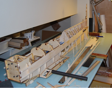
This is method I use, a la Dave Platt. A picture speaks louder than words: here is one of a fuselage under construction on a plate glass worktop.
A single straight line is drawn onto the glass for the fuselage alignment. Then a keel template that conforms with the lower profile of the fuselage (cut from 1/4" balsa sheet) is glued straight onto the glass on top of the line with CA. The keel longeron of the fuselage is placed directly onto this template, to which it is attached with masking tape. The outer sleeve of the wing tube sits on small balsa crutches to ensure horizontal alignment. To maintain alignment during fitting of the tailplane and the sheeting of the top of the fuselage and fin, additional crutches are added to support the lateral longerons of the fuselage. (This is very similar to full-size aircraft construction methods.) To answer Martin's query, these crutches are glued straight to the glass worktop with CA, but not to the longerons themselves. The whole fuselage and wing tube is then sitting very firmly on the glass worktop, correctly aligned in all planes, without any rocking whatsoever. A plumb line can be hung from the ceiling to check the vertical alignment of the fin/tailpost. When the fuselage is removed from the work top, the balsa crutches are simply knocked down and the residual CA is scraped off the glass with a modeling knife. The glass top is then cleaned with meths to remove the marker line and any remaining glue. This only takes a few seconds and leaves the glass absolutely pristine and shiny, ready for the next building operation.
I used to use plaster board to build model planes when I was young, but a glass top is now my much preferred method. Of course, you can't use pins with this method. As Dave Platt says, amusingly, in one of his videos: "Don't trying using pins, it's hell on the thumbs"!
-
I usually find the simplest solution is to do serious sanding out of doors, with the wind behind me!
-
1
-
-
Which waterplane meeting was that?
-
1 hour ago, SIMON CRAGG said:
Exactly what I do. Its a no brainer. Just keep an eye on the state of charge of the Life pack, as you do the Lipo. We have all got battery checkers these days, so easy to put an extender on the Life balance lead and job done. It really is that straightforward and certainly not a "black art"!.
Agreed. I think it's a no-brainer to check the voltage before every flight, with a load meter; it takes all of five seconds. Then one can envisage where the battery is on the discharge curve. (These curves seem to be rather similar for all batteries, although LiPOs fall off a cliff). A safe bet is not to fly once the voltage, under load, gets down to about 105 to 110% of the nominal battery voltage. I have never had any problems with NiMH batteries with this approach. The only problems I have had is when I have left a plane turned on by mistake at the end of a day - discharging NiMH batteries completely seems to destroy them.
-
13 hours ago, Geoff S said:
Wherever possible I take US threaded components and throw them as hard as possible into the dustbin and replace them with metric. I have one Great Planes ARTF Super Stearman which has some US threaded components built into the wings for the interplane struts and I'm forced to use US components but otherwise, see my first sentence. The chances of apparently correctly fitting threads failing is too great.
Geoff
I find the hassle of changing out US threaded components for metric more of a hassle than living with them, particularly as some of the US stuff (e.g. Dubro) is of good quality. It's easy enough to check the fits. Threads that are too small are obviously too sloppy often to the point that clevises can be pulled off, whereas ones that are incompatible, and tight, jam up to the point of crossing the threads.
I keep drawers of metric and US threads, but only check threads with a new model, or when I am transferring gear from crashed models.
-
One method for landing a "hot" model (particularly on a hard runway) that I found works for me is to fly it in very flat with no flap for a "wheels" landing and then flick on spoilerons (ailerons up) the instant after touch-down.
-
I sold my house in Houston, because I couldn't maintain it at a distance during Covid. I gave the entire contents to charity and all my model planes (at least six) and all the RC equipment, which were in the house, to the model club I belonged to in Houston. So that was a write-down of just the modelling stuff of several thousand dollars. Here in the UK I have spent a bit, buying several replacements!
-
I too thought you were just about done, yet there always seem to be more moulds! Anyway, it's a fantastic master-class in moulding.
-
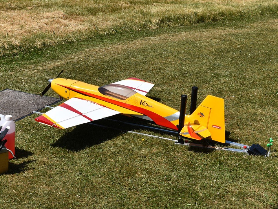
I have a device called an Airopult, which restrains the plane from moving both forwards and backwards. This has vertical posts that go in front of the tailplane, to prevent forward movement, and smaller posts that go behind the undercarriage to prevent backward movement. When one is ready to go, with the engine running, one just presses that black foot pedal at the rear of the device and the vertical posts in front of the tailplane hinge forwards, releasing the plane. The small posts behind the undercarriage collapse forward as the plane moves forward. I fix the rear of the device to the ground with heavy duty steel tent pegs (see photo). The device works very well, but it was a little pricey. I am not sure whether it is still available. But I will continue to use mine on model flying fields that do not have restraining benches.

-
Have you disconnected and reconnected all the electrical connections, including extension leads, to eliminate the possibility that this is caused by a poor connection somewhere?
-
Chris,
Looking at the pictures of the plane, the wing seems to be very far back: short tail moment and lots of aeroplane (engine nacelles, long nose) in front of the wing. Some of the drawings of the full-size appear to have the wing further forward. Also, watching your video of the model in flight, it almost looks as though some weight may be shifting about. I am wondering if you have long fuel tanks that, if not full, could be shifting the CG quite a bit as the fuel moves back and forth in flight.
-
Those aluminium clevises are great, but I found the circlips really hard to fit and very easy to flick across the room! I'd be interested to hear if you find a sure-fire way, or special tool, for fitting them.
-
Wouldn't it be safer with no flap at all?
-
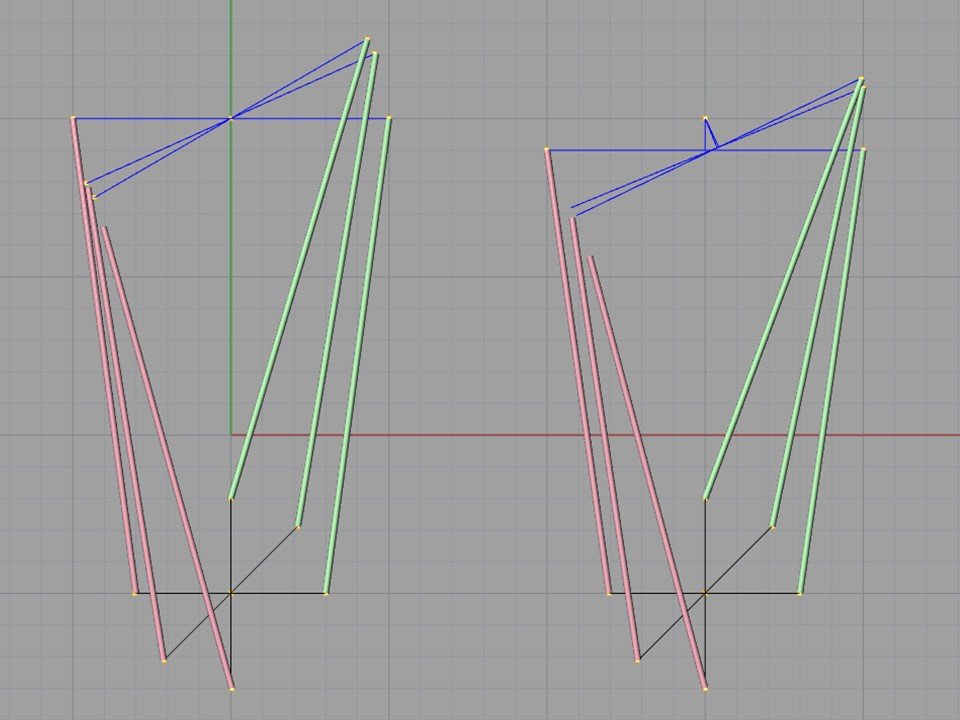
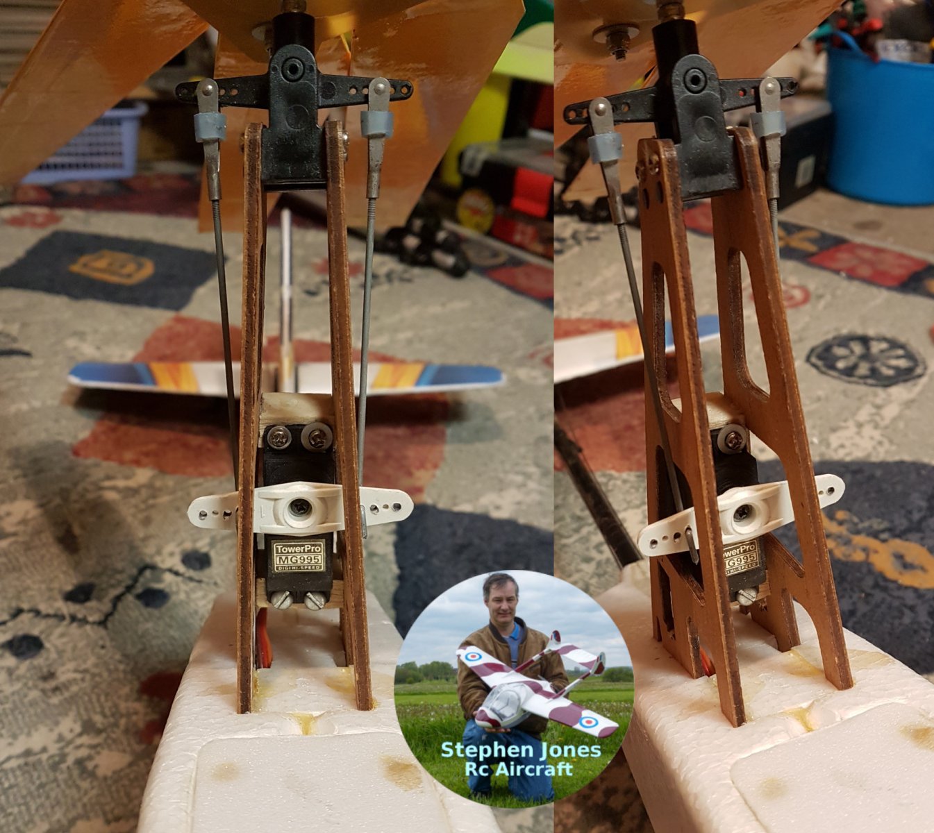
Stephen,
I realise that my comment was not very well expressed. I think I can explain better what I meant with a rough sketch. In my sketch (which is not to true scale), the right-hand pushrod is shown in green, and I have kept this attached to both the servo arm (black) and the bellcrank (blue) as the servo arm is rotated. The left-hand pushrod (pink) then falls short of the bellcrank as the rotation occurs, or tries to occur! I made two alternative sketches because I was not 100% sure where your bellcrank pivot point is relative to the bellcrank arm.
The problem arises because the servo arms and the bellcrank arms are of different lengths, so that symmetry is lost when the rotation occurs. My sketch also shows the extreme case of 90 degree rotation, simply to make point clearer.
The problem is solved by making the servo arms and the bellcrank arms the same length.
I came across this problem when I set up a pull-pull rudder with different length servo arms and rudder horns. I managed to bust a pull-pull wire that way!
-
On 18/04/2021 at 23:56, Stephen Jones said:
Well I took 3 auto gyros to the field today the weather was warm but muggy with a nice scattering of clouds ?
I wanted to test my Auto G and my new Prize Jumper T Lite.
I set my Auto G up the nite before using a Rx battery all set up fine.
When i got to the field decided to to a range test 1st but could not get my Rx to work then i noticed smoke coming from my Esc so that put a stop to that then.
No idea why it happened i can only assume the large Servo was drawing to much current.
I had a Frsky V4 Rx two 9 gram servos and as you can see the Tower Pro MG995.
So I could not test the T Lite radio or my Auto G ?
So i flew the Mk1 Lidl Autogyro which would not track straight along the ground Although i managed two flights with it i broke the undercarriage of due the hard ground and rutts ?.
So next was my Mk2 Lidl Autogyro which does track well across the ground and get airborne fairly quickly despite their being no or very little wing today , I did discover i needed to pitch down and applied more power due to the lack of wing.
The hazy conditions did make it a little difficult at times to see the model.
So two broken models and a warm day out with a little more practice under my belt so can not complain.
Steve
I don't think the geometry of the push-rods between the servo arm and the bellcrank can quite work. It's subtle, but the distances between the ends of the bellcrank and the servo arm change slightly with rotation, whereas the push-rods can't, so the servo is over-stressed.
-
It's all a question of cost and the time taken to learn how to use them. They range from freeware to packages costing 4000 to 5000 pounds. I would try Profili and/or Compufoil first (they are very cheap), to get into the swing of things, and then some of the 3D CAD freeware on the internet. You will have to Google that, because I am not up-to-date with what is available. It is really is best to go for 2D rather than 3D from the outset.
The top of the range are the big packages like AutoCAD and SolidsWorks, which is probably the very best - it was used by Boeing to design the Dreamliner, for example.
Then there are the low priced packages (100 or 200 pounds), which are pretty good as far as they go, but have serious limitations. I tried TurboCAD, DoubleCAD, DevCad, TotalCAD, Alibre Personal (there are trial versions of most of these). This process drove me nuts, because each program would look so hopeful at first, and then one would find a show stopper for model aircraft design, such as an inability to bring in 3D point clouds or angle rotations only in increments of one degree.
I ended up using Rhino, which is in the middle price range (about 800 pounds). This does everything one could want, but is not fully parametric: when you edit one part, you have to edit the adjacent parts, whereas the top-of-the-range products do that automatically.
It's really a question of whether you get sufficiently interested in 3D CAD to invest the time and money - really you have to treat it as a sub-hobby and expect to take about a year to become really proficient. None of these packages is difficult to use, but they are very complicated, with an enormous number of commands and different ways of doing similar operations.
If you like drawing with pen and paper, you will probably fall in love with 3D CAD; otherwise, it may not be worth your while. I personally think that it adds a whole new dimension to aeromodelling.
-
1
-
-
Profili2 and Compufoil are two cheap packages that do the job. I slightly preferred the latter, because it allows one to import arbitrary wing planform coordinates. Both these applications are limited in what they can do, and you may find that it is worthwhile in the long run to acquire and learn to use a full 3D CAD program.
-
1
-
E10 petrol
in IC Engines
Posted
E10 was not an initiative of the oil companies, and I am pretty sure they don't make more money with this fuel than E0.