
Sam Wragg
-
Posts
390 -
Joined
-
Last visited
Never
Content Type
Profiles
Forums
Blogs
Gallery
Calendar
Downloads
Posts posted by Sam Wragg
-
-
Principally most modellers are trustworthy but others would poke you're eyes out and pee in the sockets to make a quick buck.
Trust your instincts

-
Do you use 1 pack to drive both motors / Esc. If so; could it be back emf affecting the other Esc? Have you tried using two indipendant packs?
good luck
Sam
-
Ive seen this before and it's when another coat is applied outside the curing stage window of the previous coat
could it be because the base coat at its curing stage And because of this its reacted with the top coat.
Good luck
Sam
-
Why not run the Irvine on a tuned pipe & swing a bigger prop than the OS= more power / less noise
S -
Remove the Positive wire off one of speed controllers where it plugs into the Y lead.This will disable the Bec of the esc which is causing the problem.
Sam
Edited By Sam Wragg on 03/04/2015 08:16:31
Edited By Sam Wragg on 03/04/2015 08:18:35
-
Yes Martyn I reckon this is where most people go wrong, time spent at this stage reflects on the outcome of the finish.
When I'm finally satisfied that the surface is as good as possible I seal the surface prior to laying on the glass cloth with a mixture of Finishing resin which consists of:-
- 15ml Finishing resin
- 5ml Epoxy thinners (or Acetone)
- 1 Teaspoon of Micro Balloons
I thoroughly give this a good mixing then spread the resin evenly over the surface
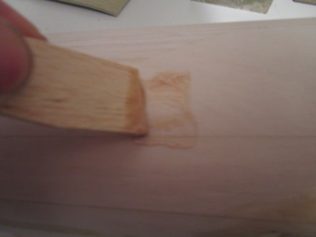
Some recommend using an old credit card or a piece of stiff card to spread the resin mixture I've found that a piece of 1" wide 1\16 balsa works just as well . This small amount of resin will spread by this this far..... (see image bellow)
I know the above image isn't very clear but it shows how far the small amount of resin spreads ( an area of roughly 3"x2" ). The amount of resin mixed was more than enough to cover half of Arrows fuselage. When the resin sets I can then complete the rest of the fuse.
Sam
Edited By Sam Wragg on 31/03/2015 11:48:17
-
Right then fellow enthusiasts here we go,
First of all i don't want to come across that my method is the best as I know there are various methods that other modelers use and prefer. My way of glassing was learned over years of trail and error and every time I glassed another model I learned a bit more until I developed my own preferred method.
First of all the key element to glassing is surface preparation, time spent on this stage dictates the outcome of the final finish of the model.
Firstly I take my time and spend many hours filling any surface defect with lightweight filler and sanding back the surface using sand paper & sanding pads until I'm happy.
I'm only happy when i can hold the model up to the light run my fingers over the surface and can see nor feel any surface blemish
These are the sanding pads I use which are obtainable from Automotive paint suppliers and can be used Wet or Dry
What I find is that these pads follow the shape of the surface allowing for an even all over finish.
On average it will take me around a week to prepare the surface.
Sam
Edited By Sam Wragg on 30/03/2015 11:04:28
-
Remind me not to become an Engineer next time round....... Its a thankless task.......Underpaid & undervalued...
...Well; you are in this country that's unless you're a "Domestic(joke) Engineer"
Sam
-
As my late Dad used to say....... "As long as it looks all reyt in air, is all that matters"
For me, flying is the product of building....... you have to build to be able to fly.
I've/we've spent many an hour discussing how to improve a design and putting our thoughts into practice. To do this you have to build your own..... this is where the enjoyment is...... welcome to the wonderful world of Engineering
This is what acedemics in schools have missed and now we have a serious skills gap
Sam
-
I concur, very nice indeed and I bet the colour scheme will show up well in flight.
The ARTF fraternity don't know what they are missing?.... You cant beat that feeling of satisfaction of creating something out of a set of plans and a pile of wood then seeing the product of your efforts take off into the wide blue yonder for the first time.
Sam
Edited By Sam Wragg on 28/03/2015 09:57:09
-
A pattern prop (apc)is generally anything above an 8" pitch ie 10x9/10/11/12/13/14. Using this type of prop reduces the noise footprint of the model, which is crucial in F3a comps (pattern),and also for everyday use.
N.... ie 13x13.5N. Signifies a narrow blade which puts less load on the engine allowing it to turn greater pitches with reduced down line braking effect.
W.....ie 13x10W. Signifies a wide blade which increases the load on the engine with better braking effect.
E.. Signifies a blade/prop specifically designed for Electric propulsion systems and is NOT designed for I. C use. As a matter of extreme safety do not use on an ic engine
An ic prop is a lot heavier than an equivalent electric prop.
If you was to measure the current drawn by an electric motor and compared like for like between the same size electric & & ic prop you will find the current draw will be significantly higher for the ic varient of prop
Hope this helps
Sam
Edited By Sam Wragg on 24/03/2015 19:55:22
-
Select the brake function on your esc and use your throttle trim to to activate on landing to stop the prop from freewheeling then you can blip the throttle on landing to get the prop to stop at around the 3.....9 position
Sam
-
Hi Martyn,
Over the years I have read up & tried many methods of glassing and come to the conclusion that unless you use the Vac Bag technique you can guarantee one thing........ plenty of elbow grease will be required, some more than others.
Nevertheless I have developed my own preferred method that seems to work but still not looking forward to undertaking with the only driving factors of that it strengthens the airframe and completely fuel proofs it.
If there's enough interest i will give a step by step account on my method as I go along
Sam
-
All work and no pleasure is slowing thing down now but beginning to see the end of the build now, all that is required is to manufacture the Belly pan and form the Wing fairings.
Belly Pan
A simple task of cutting some 3/8 Balsa sides (Tack glued on)
Note the 1/16 gap between the L.E/T.E of the Fuzz
Top sheeting in place (Gorilla Glue) then carved and sanded to profile before removing the belly pan from the wing
Completed Belly pan prior to covering
Wing Fairing
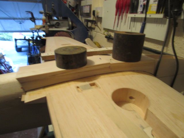
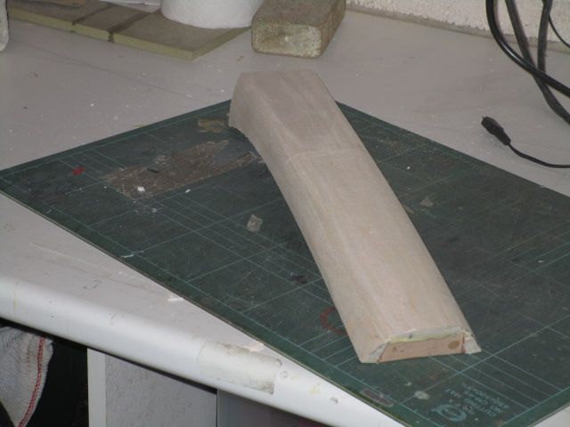
This was achieved by bonding 1/32 ply to the fuselage and Gorilla glue to fill any gaps using the wing to hold the ply in position then in-filled with 1/2" triangular carved to shape prior to gluing on using Cyano then filling using Model Lite filler
Arrow "in the flesh"
All that's now required is a bit of titivating before Epoxy Glassing the fuzz/Belly pan & Pro-Filming the Wing and Tail surfaces
Sam
-
Apc I believe are designed to be quiet
Sam
Edited By Sam Wragg on 17/03/2015 15:29:25
-
Great to see Concept nearly there.
Re OS61, Martyn I suspect you may have throttling problems due to the large throat area and a pump may be required due the lack of suction of fuel because of this fact, although I may be wrong.
I have read that with this Engine modelers have had success in changing to front induction with an increase in power over the RF version . Nevertheless I would run the engine using 10% nitro and see how you go on as it shouldn't stop you from tuning the engine to the pipe (after a period of running in). Leave the pipe slightly long as the engine unloads in the air if you suffer poor throttling try a smaller choked Carb as idealy this will give you more torque and suction.
Revs..... aim for the mid ten thousands as this keep the noise down and go for an Apc 12x9 minimum, I feel the 12x8 you intend to use will be too fine a pitch for your OS.
The OS61 in my Magic was new at the start of last season and the pipe was set long, by the time we last flew at Montfort Bridge I noticed that the engine had come on song and suspect I may have to go up in pitch to a 12x10 to maximise the power.
Welcome to the delights of tuning piped 2 stroke engines
Sam
-
It's glass bodied version, the kit is complete with nothing missing.
I first bought this kit 1979 when I was an apprentice. It was fitted with a redshift 60 and managed to fly it just the once in the spring of 1980 simply because our flying field was just that? I put it away and got distracted by learning my trade and the oposite sex (and forgot about the hobby).
10 years later I got the bug again and discoverd that my Gnat had been thrown away by my Dad.
I never thought I would aquire that model again up until last week when I managed to secure a kit.
Now a very happy man & will probably electrify and fit retracts just to keep the lines of the model
May do a building blog when I get some projects out of the way first
Sam
-
Just aquired an unbuilt kit of the Gnat.

Sam
-
Paul great tip, Dave thanks for the link i will no doubt use for future planed builds.
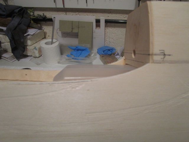
I decided to rout a 5/8 deep recess to overcome the issue the tank fouling.
5/8 deep recess prior to lining with 1/16 Balsa
Lined recess.... Note 1/16 ply cross brace web sunk in 1.1/2" back from the leading edge to support the Wing Dowel
Problem solved. I can now glass the center section of Arrows wing
Sam
-
It really ticks me off when people go knocking the HSE.
H&S is there for a reason .... Its to reduce the risk of accident, injury or fatalities! Simples..........
....The problem is its the jobs-worths of this country who hide behind the mask of H&S for whatever reason. (mainly because its easier to do so without citing any particular reason).
All you have to ask is
- What hazards have been identified?
- What control measures have been put in place?
- Where's the risk assessment?
Generally these jobs-worths have come out out University indoctrinated and devoid of any common sense simply because they've acquired no real life experience.
DON'T BLAME THE HSE. BLAME THOSE WHO APPLY IT
Sam
-
As above......No I don't think I'm bing cynical
After many years of dealing with the modeling fraternity at some stage each point I raise will happen leading to the demise of a good idea
Sam
Edited By Sam Wragg on 05/03/2015 14:17:53
-
Posted by Sam Wragg on 24/02/2015 20:50:36:Posted by Sam Wragg on 24/02/2015 15:39:33:
I can see the merits of a national model center but I can't see it working due to these factors
1 Fun police / jobsworths
2. Inconsiderate modellers who think they can do what they please.
3 impracticable for most people to go there and fly
4 it will only end up benefiting the chosen few.
Am I being too cynical
Sam
-
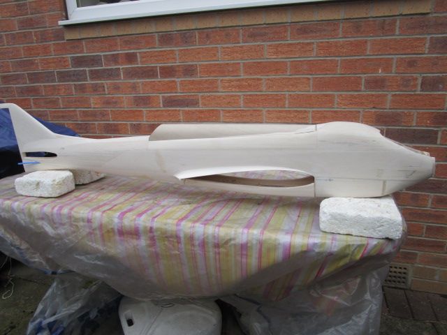
In the initial stage in building the fuselage it became apparent we was going to have Fuel tank issues as the tank specified was clearly intended for competitive flying giving you just enough duration to fly a schedule.
Experience dictates that fitting 14oz tank is the correct size using a 60/90 engine for everyday flying giving roughly a 10min engine run.
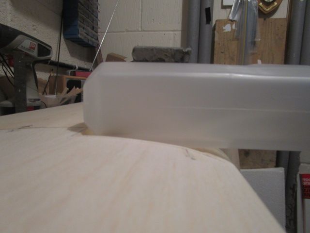
Looking at all the readily available tanks it was looking like 10oz was the maximum size that would fit simply because clearance was required for the fuel lines up at the bulkhead for the engine pump unit? In a flash of inspiration I remembered I used to use Mk & Tetra tanks. A quick search and I found that a 14oz Bubble-less Tetra tank would fit (just). This was obtained from Central Hobbies.
As you can see the tank just fits but a Well is required cutting into the wing to clear the tank.
To be Continued
Sam
-
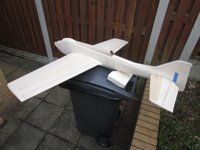
Unfortunately Work Work Work has got in the way of Arrow, so finally this week end we have managed to find time to crack on with the final stages of the build.
Time to join the wing panels.
Wing Panel with the top surface laid flat then raised 5mm up at the root then weighted with wedges holding the wing center line true in position awaiting the opposite panel to be offered up
Wing panels aligned and glued together using 15 min Epoxy.
Sam
Edited By Sam Wragg on 01/03/2015 17:51:46









Clive Weller's Concept
in Classic Aerobat Build Blogs
Posted
What can one say apart from its sad when this happens.
Keep your chin up Martyn
Sam