
Chris North 3
-
Posts
832 -
Joined
-
Last visited
Never
Content Type
Profiles
Forums
Blogs
Gallery
Calendar
Downloads
Posts posted by Chris North 3
-
-
Flite test spit fire or racer - both are easy to make from and fly great. I didn't have foam board so made mine from 5mm depron with packing tape on one side.
-
Having read along with this thread, it seems that your ideas are not the problem here Peter but rather the ability to peak your interest enough to commit to the effort required. Perhaps then there is an opportunity here to identify someone (may I say younger without causing offense?) from this thread that is interested in getting into model design that could work with you to do all of the leg-work of getting your ideas on to paper and into the air. You could then act as director and mentor showing how to get the design from brain to drawing board to building board and into the air. While face to face is obviously the best, given all of the communication options available to us these days this could just as easily be done remotely.
RCM&E is always calling for ideas for new articles and so perhaps his could be a good follow on to your previous design article.
I know Lindsey Todd's articles on Renaissance covered a similar topic but - and no disrespect to Lindsey if he is reading - this was from the point of view of someone who has designed plenty of models and so some of the interesting parts, such as material sizing, were not really explained in much detail.
Anyway its just my opinion and worth any more than anybody else's, but it would be interesting to hear the process from both the new designer and the mentor's point of view for the same design activity.
-
I would recommend the Flitest Spitfire (original speed build) - there is a free plan to download, a build video to follow on line and the plane flies great - I actually learnt to fly with one - plus it has a good all round appeal.
Everyone can either build their model at home or you could have a club night build along session.
Only suggestion I would make is to add some strength around the wing holding lugs to prevent them from pulling out of the foam in a unscheduled arrival. Ac couple of square of plastic from an old credit card or club card is ideal.
-
Looking good.
-
Looking good Geoff. I love the idea of a laser but just not sure I would get much value out of it given the amount if building I'm doing. Following your build
-
I may be wrong but I understood that Pheonix Sim was part of the Spektrum / Horizon brand as it was always bundled with their transmitters and had a number of the various Spektrum based planes. When they took over Greatplanes they also took over Real Flight sim and so rather than keeping both going they have chosed RF and closed Pheonix. This is why all the Horizon Hobby planes are now on RF instead.
I have found RF to be just as good and less graphic intensive
-
Thanks for the feedback. Sounds as if new is the way to go!
-
Great looking build and nice detailed build blog. I was thinking about PS2 as a next build but now I see what Peter is working on............
-
Hello - I have a 4 cell 2000mAh NIMh battery in my 10J transmitter that came when I bought it a number of years ago. For various reasons I have not used the transmitted for around 2 years and now the battery is discharging very quickly.
I am using the transmitter on my simulator to get the fingers and thumbs back in action but the transmitter battery only lasts about an hour before I get a low voltage alarm.
I have tried charging the battery with the battery charger on the NIMh setting at 2A (=1C). It charges to full in around 10 mins and then discharges very quickly once back in the transmitter.
My question is is this pack dead or can it be resurrected? if so how do I go about doing this?
Alternatively can I use a lipo as an alternative to the MIMh Tx battery pack and if so what would be a suitable size?
Appreciate any advice
-
-
So there are a few things left to do but essentially she is ready to fly - although for various reasons that may be a couple of weeks away.
Left to do:
- Adjust throws to correct max values;
- make up and fit windscreens;
- make up and fit rear head rest;
- cut a hole in the base of the hatch for cooling air to escape;
- find a couple of pilots;
- make up and add a few decals;
- buy some locktight and apply to the motor mount and wheel collet screws.
I had hoped this would be a quicker build that the Batty but again 6 months seems to be my time frame. Given that I generally have to travel every other week and when at home get to spend an hour a night, 3 or 4 times a week then I am fine with that - plus I find the building relaxing so have no problem how long it takes.
Thanks to all those that that gave support and advice along the way and especially to peter for your ongoing support.
I'll post another update in a few weeks time or whenever I get the chance to test fly her.
Looking forward to it!
-
-
Well this weekend I managed to get a few of the final items complete on the Ohmen.
With the rear end in place I was able to mark-up the horn locations for the rudder and elevators and once these were in place i could trim the snakes to length. This took a little juggling but after a bit of adjustment to get the servo arm lined up at the center position - the arm is never at 90 deg to the servo for some reason!
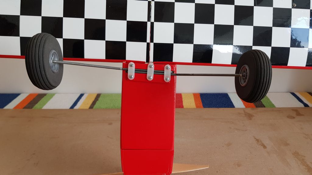
With all of the control complete the next task was to cut the undercarriage legs to length as i had previously bent them from a single piece of piano wire. I initially tried using a hack saw but soon realised that the cut off disc on the rotary tool was a much better option! Once cut the wheels were attached and collets installed to keep everything in place. A small flat surface was ground into the wire surface using a sanding disc (again on the rotary tool) to help key the collet grub srew.
The under carriage legs were inserted into the locating holes in the base of the fuselage and pushed home. Now I had contemplated buying some double 3mm wire clamps however the postage from the UK was twice the value of the clamp - insignificant I know but its the principle!
So instead I used some flat clamps and made up a couple of guide rails from 3mm ply that I covered and then aligned either side of the under carriage legs before drilling some pilot holes and then screwing everything in place. I am sure that 2 clamps would have been more than enough but 3 seemed a better choice with the full width rails.
And then all of a the main build was done ....well almost but we'll come on to that shortly!
-
I see that the control throws are on the build article summary so apologies
-
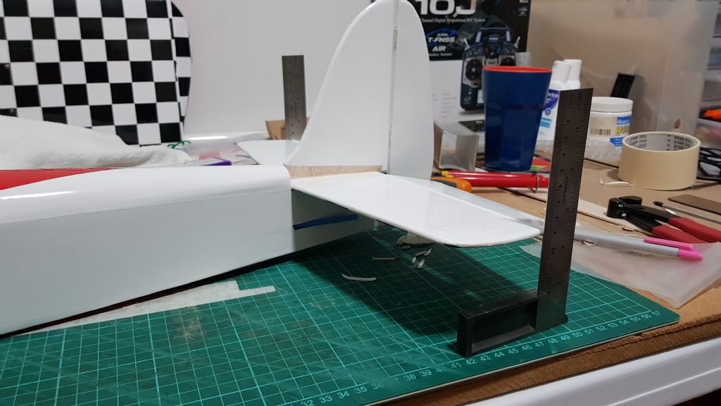
The fin and horizontal stabilizer were dry fitted ensuring the tail was level and centralised. While in position the film on the bottom of the stabilizer was marked and then, using Trevor’s suggestion, was cut away using a steel ruler and the tip of the soldering iron. This was repeated on the top around the fin and with the film peeled away the fin was centralised on the stabilizer and glued in position using a couple of engineer’s squares to ensure it remained at vertical. This was set aside overnight.
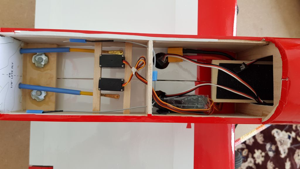
Having completed the aileron connections, I made a start on the rudder and elevator controls. For these I am using snakes which seem to be very easy to set-up. To position the servos , I inserted a snake into one of the outer tubes and then adjusted the servo on the pre-installed rails so that the snake was as straight as possible. This was repeated for the second servo – again I forgot to take a picture.
I was planning on installing the rudder and elevator control horns before attaching the tail section but found that it was a bit difficult to hold the fuselage, the tail and the control horn all at the same time. I tried using some tape to secure the tail as shown but eventually decided to install the tail so that everything was secure in position.
trying to position everything with one pair of hands..
Installing the tail and making sure that it is level by ensuring it is the same height either side
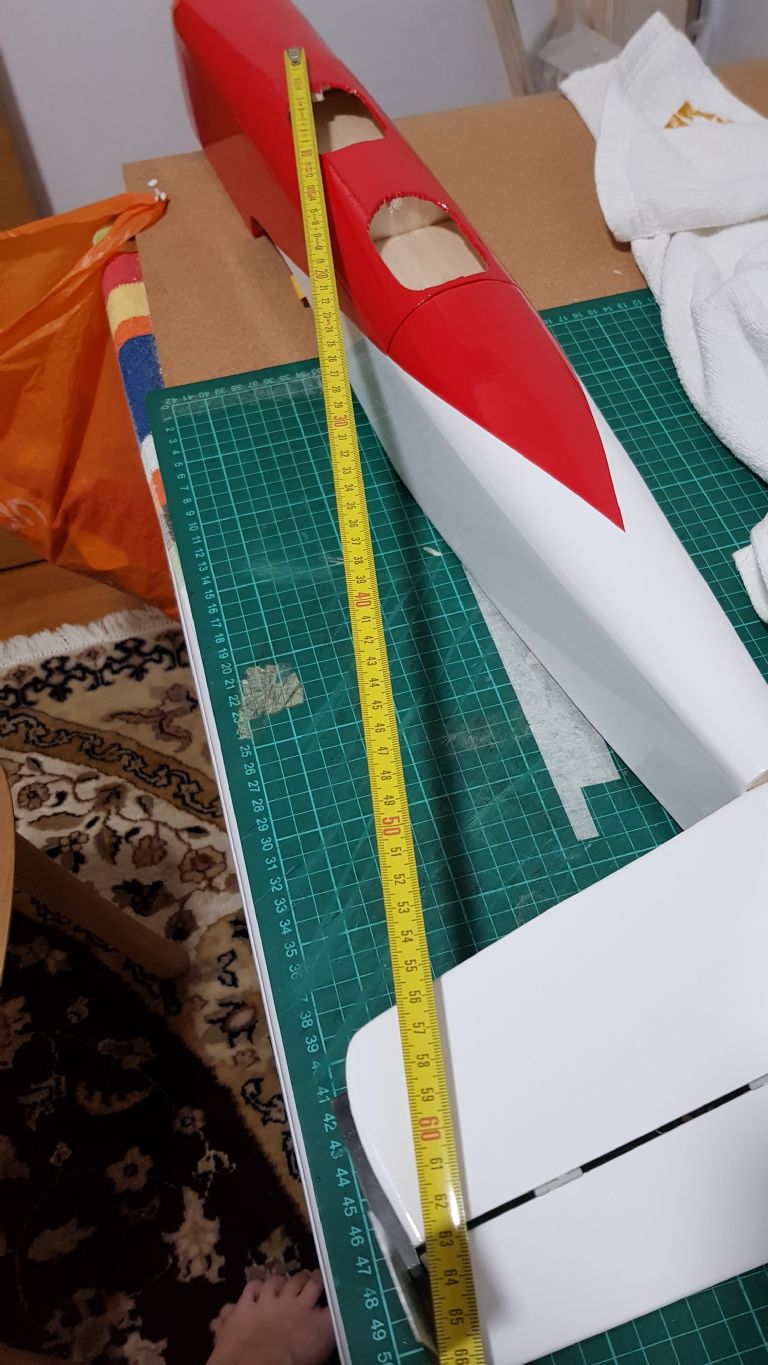
Using a tape measure from the hatch latch back tot he tip of the stabiliser on each side to make sure that is is central.
With everything in position it has been left to dry overnight so hopefully tonight and over the weekend I can get most of this completed.
A quick question for Peter - apologies if this is in the build article somewhere - but what do you recommend for the travel on the control surfaces for the first flight as I don't see any mention on the plan?
-
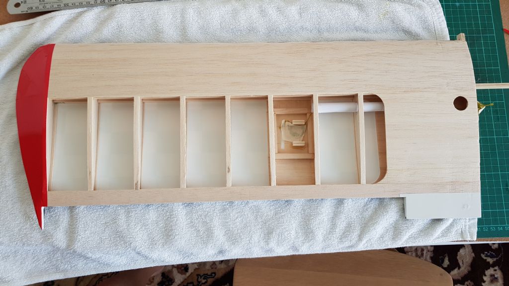
The servo plates have been cut free from the wing and servos installed. Extension leads have been attached and their joints sellotaped to ensure they do not come apart. The film was removed from the access holes on the top of each wing and the pre-installed strings used to pull the cables through. The length of the cable tubes are actually quite short so it may have been possible to thread the cables without the strings but it is certainly much easier and quicker with them.
As suspected, one of the plates had moved slightly during covering and so once cut free the covering pattern did not match up. This was easily fixed by removing the covering and reapplying an new section that did match.
I decided to use metal push rods that I had in the spares bin on the ailerons. These were cut roughly to length and then inserted through the push rod clamps installed on the servo arms. With the clevis installed into the horn, the horn was then positioned such that the holes lined up with the hinge gap. Positions were marked, pilot holes drilled and the horns screwed in place using their backing plates.
Once everything has been set-up and throws adjusted I will trim the linkages to a more approriate length
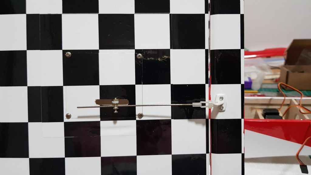
-
Well, other things have been getting in the way recently and so I have only ben tinkering with the Ohmen over the past couple of weeks. That said things continue to progress although when I do do something, I forget to take photos. Anyway, here is a quick update before the weekend.
The cowl is now covered and finished. I started by trying to cover it in a single sheet of film but my ability did not match my assumptions and I was getting a large number of wrinkles around the spinner ring that I couldn’t get out. I am sure others would be able to achieve it however I took the easy way out and covered it using 4 or 5 pieces. It turned out ok although I need to go over it and remove the white glue lines that have shown at some of the overlap edges where the film has shrunk. It looks fine from a distance and so is not a big deal ... but I know they are there!
While the cowl looks and fits fine I have to say I’m not loving it. I followed the plan (I think) but my air vent at the front is wider than it is tall whereas when I look at pictures of Peter’s model it is taller than it is wide. Maybe I have made it wrong but it looks a bit odd and so I am contemplating making a new cowl. Its certainly not urgent nor will it stop the model flying but something that I notice.
All of the control surfaces are now glued into position and moving freely. One of the elevator hinges is a little stiffer than the rest due to some glue ingress but it is not overly tight and should be fine. Its certainly not stiff enough to add extra resistance to the servo. I must remember to protect the hinge pins with Vaseline next time. Something simple that saves heartache later (or would have!)
-
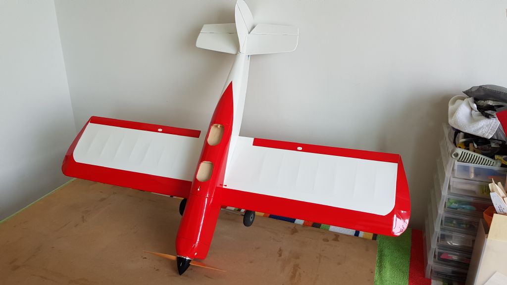
So what to do about the front of the fuselage? At first I thought a simple transition from red to white to match the wings but after mocking up this looked a bit boring. So, given that a little extra effort often results in a lot better outcome, I decided to make it a bit more subtle.
At first I thought that a sweeping curve would look great but this meant making sure everything matched on both sides and so to make this easier I simply kept it straight on both sides.
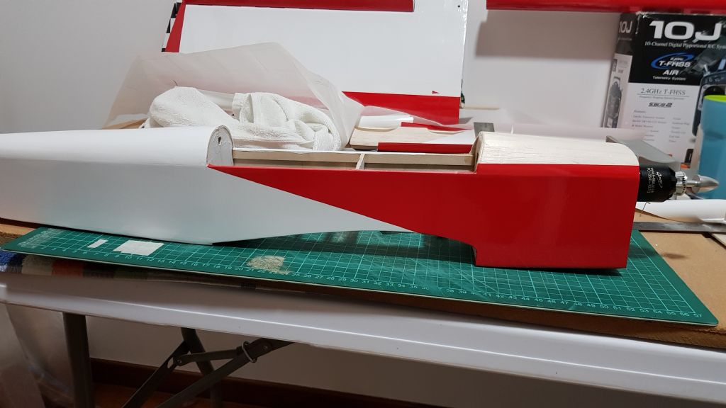
And then finished the front by adding red to the top of the fwd fuselage

Thinking that the cockpit would look a little strange in white I went ahead and covered this in red too.

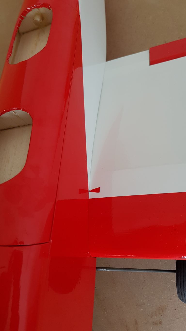
So this is where I am up to. I just need to open the cockpits and have a think about whether I need more trim aft of the hatch - I am thinking a triangle of red to tie everything in
What I have realised is that I have not made the head rest to go behind the aft cockpit but this can be added after.
When attaching the head rest or indeed attaching the horizontal stabilizer and fin how do people remove the film without cutting into the wood below? I am assuming the easiest way is to use the knife but I suspect that my heavy handedness will result in some scoring of the wood underneath. I would be glad to hear any ideas or tips
-
-
So onto the fuselage.
The plan was simple white at the back, red at the front. To keep it simple I also decided to have full red on the bottom which would hopefully contrast with the checks.
White was then applied from the forward section of the wing bay back to the tail.
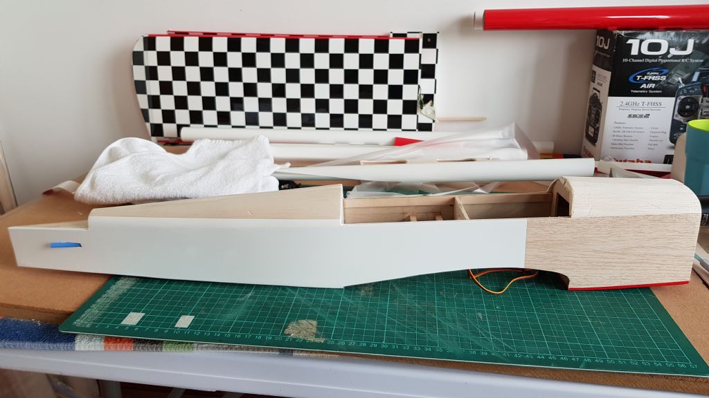
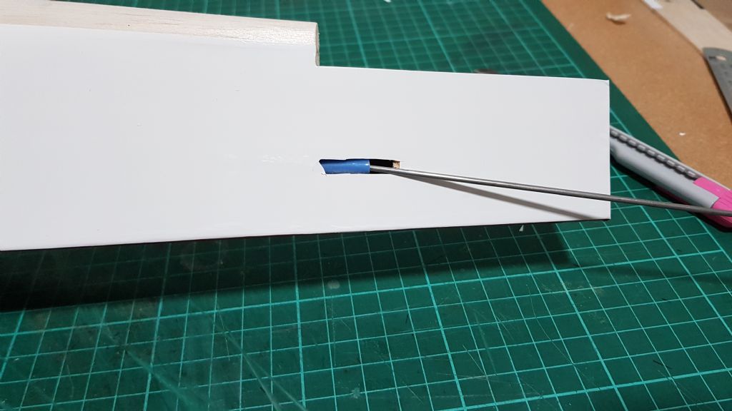
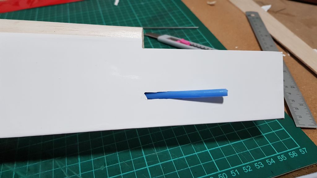
Note that while the snakes are installed they are not glued into their final position yet. So to save having to try to cut around the snakes I simply pulled them through so that they were just below the surface of the fuselage. The film was then applied over the top, the opening cut out and the snakes pushed back through. A small length of wire was used to help lift the snake over the lip of the fuselage.
Snake pulled inside fuselage...
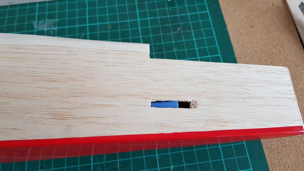
Opening cut our and wire used to assist snake back out of fuselage...
-
Next up was the top of the wings.
I did contemplate covering the wing fully in white and then adding white trim, which in hind sight may have been a better idea since the whole surface could have been covered using a single piece of film (the same I had done for the underside), but since I don't like wasting things and was happy for the challenge I decided to cover the wing in sections.
My original idea was simply to have a white wing with a plain red strip along the front. I had read that wing tips should be covered first which created the challenge of how to cover the wing tips in two colours when the tips are such an open design. After a cup of tea I simply decided to change the colour scheme and so simply covered the tip in red. The film was lined up with the edge of the tip cap strip and care was taken to make sure a low heat was used to stick the edges before shrinking the tip.
Note that I covered the root trailing edge section with white film so that i could use a smaller section of white when covering the wing section. Given the size of of the ailerons this probably didn't save much to be honest.
Next up was to cover the rear section of the wing with white. A faint pencil line was drawn across the wing to mark the location of edge of the film assuming that the red would overlap by around 5mm
Now I am sure a square join at the wing tip would have been fine but after looking at it I thought I'd prefer a curve. So with the aid of a spool of fishing line I cut a couple of curves into a square of film and attached this at the wing tip.
Being smart I lined up the curve with the top of the white film to make a nice flowing arc but, being daft, I forgot to take into account the fact that the red film would overlap the white by 5mm! Still not to worry - it would be a defect to show that this is not an ARTF!
While panel complete and red curve added...
And red stripe added to complete the wing....
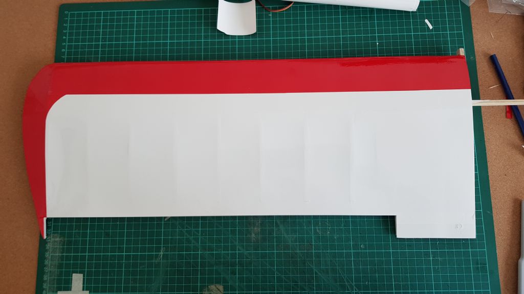
While I initially planned on white ailerons I had the red film out so covered these red as well.
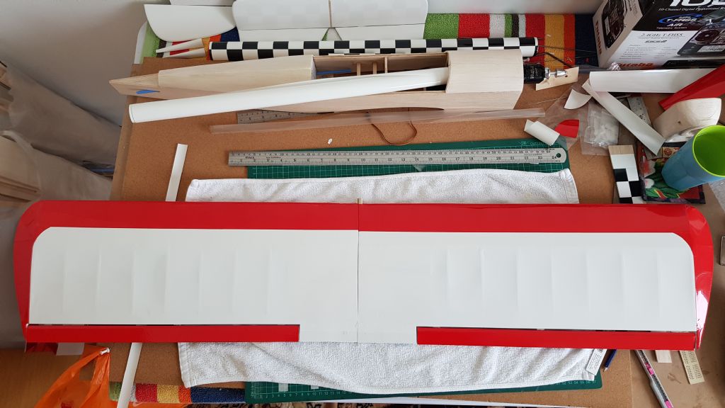
You will note that despite measuring the wings up, there is a slight difference in the depth of the red stripe but this won't show once the wings are on the fuselage.
-
So I started with the wings.
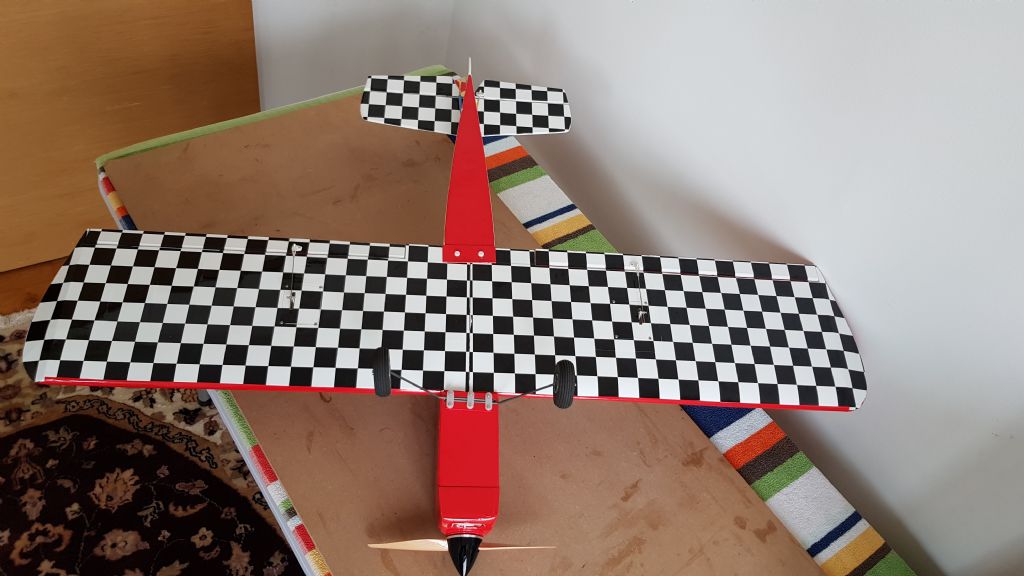
First each underside was covered in check film. The film was cut over size and the trailing edge used as a guide to get the check square. Note that the servo hatches are in position during covering and will be cut free once I start to install the electronics. This worked fine for the first wing panel but it looks as if the cover has slipped slightly on the second. this may mean the pattern on the second hatch does not match once cut free and installed properly but if so then I can always recover the hatch.
Underside of wing panel.
I then covered the underside of the aileron taking time to install it back into the wing via its hinges to ensure that the film lined up properly. This means a bit of extra off-cut and wastage bit it is really only the width of a square as every second one lines up.
-
It has been a while so i thought I'd give an update on where I am at with the covering. The covering is taking a while as work travel has limited building time but also I have been making the pattern up as i go along. In hind sight it would have been easier to have made a clear plan and then to have cut some of the larger pieces to shape rather than making the design from smaller pieces.
I am using hobbyking covering film in white, red and black and white check. I use an iron set to around 100 deg for sticking the edges and then increased to around 123-130 deg to shrink the film. The temps may not be that accurate as I simply use the manual gauge on the iron. Initially I was getting a lot of shrinking while attaching the edges but then I realised that the temp dial rotates more than 360 deg and so while i thought the dial was on low it was actually going round for a second lap!.
Once this was sorted out things got back to normal and I could easily stick the edges before shrinking the main area.
I found that the red file is a bit heavier than the white and check films and that as such it needs a bit more temperature to seal and then to shrink. The white film is easy to use but I find that it is a little opaque and that you can see where two layers of film are - such as at joints etc. Anyway, apart from that I have not really had too may issues.
I know there are lots of descriptions of covering and, based on my work, I am no expert so for the sake of the blog I will simply explain the sequence rather than the process. My sequence is based on back to front and bottom to top in order to keep overlaps running with the airflow.
-
So with that all done the board was cleared and the dust removed before continuing on with the covering.
I only have a limited supply of the HK covering so it is not going to be flash but hopefully I can create a neat high contrast design. I find the film very easy to work with although the heat setting has to be at the very bottom range of the iron otherwise I end up shrinking and sticking at the same time. I have not tried overlapping the film for a two colour design so will see how that goes.
Travelling again for a couple of days this week so no more covering until the back end of the week.

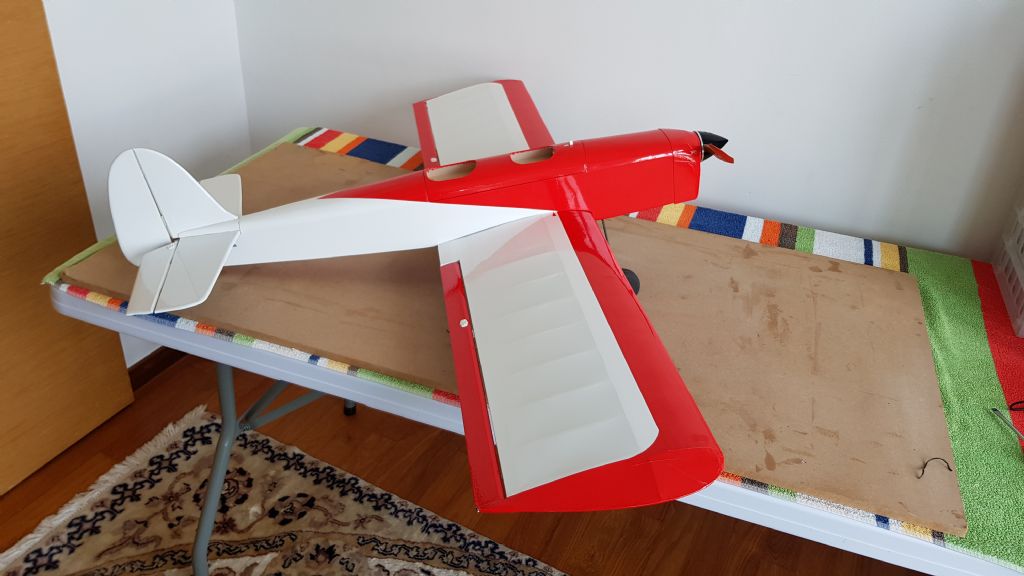
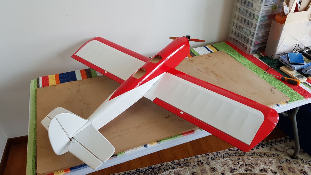
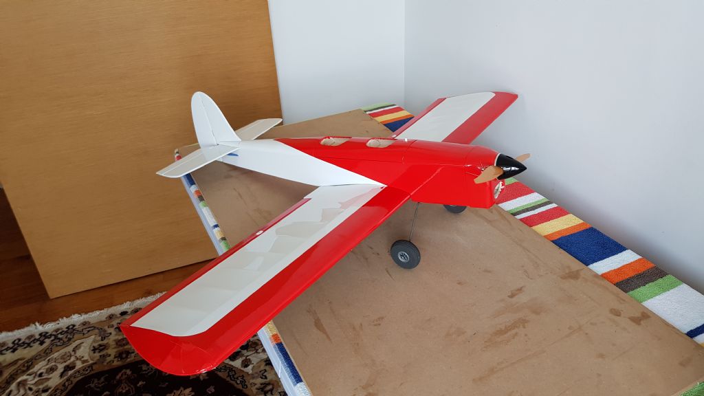




Mark's Peggy Sue 2 Build
in Peter Miller plan builders
Posted
Its looking fantastic. I am envious of your skills and patience!