


911hillclimber
-
Posts
566 -
Joined
-
Last visited
-
Days Won
2
Content Type
Profiles
Forums
Blogs
Gallery
Calendar
Downloads
Posts posted by 911hillclimber
-
-
Rods came from ebay, 300 deg MP as opposed to 400 and higher.
Will look at those Outerzone designs.
-
Is there another source for the castings of the Atom Minor Mk3 other than Hemmingways?
-
Filler rod arrived today, I even read the instructions!
Decided to test trial the job first, so found some nice alum sheet, 16 swg and formed a simple corner joint, about 30mm long. Thought I would try the butane torch first as per the instructions as it is butane gas.
The torch could not get the sheet alum hot enough to melt the rod.
So, reverted to my mini gas welding set that will gas weld 16 swg steel well, that should do!
No, the sheet got hot ok, infact to melting point, but the rod simply would not take to the freshly cut surfaces. I opened the intended welded joint by hand after quenching.
Frustrated (as ever) with this saga took, the cast back plate to the vice and csk sunk the one lugs with a centre drill, so the surfaces were very clean. The hole is about 2mm dia x 5 deep, open, the csk is open to about 5mm dia and 4 mm deep, a good funnel I hoped.
Heated the casting gently for a minute or so and focused on the one lug.
Heated and dabbed the rod to the csk hole, nothing happened, hotter still and the rod sort of lost it's tip on the surface, but did not flow, just there as a small lump. Tried more and the casting lug as good as melted.
What rod was there picked out after quenching with a scriber.
So, I conclude the casting are made of peanut shells, melts at a temp lower than the rod (300 degC) and the rod will not take to the casting, or sheet aluminium or peanut shell castings.
All in all a waste of time, money and gas.
Maybe one day I will buy some new castings for £67 and try machining again, but do not feel inclined to carry on.
-
Thanks for the details. Hemmingway are the company now selling the materials/castings for the Atom Minor Mk3.
-
Are those Hemmingway castings?
Mine look nothing like as 'matched' as those in the running engine.
-
Sounds good, advice always appreciated. all a bit like chamfer the edges to be welded for best/total penetration. A good counter sink hole is easy as you know. This is for the end plate lugs.
For the main case I have M3 alum screws on order so will red loctite them in and flush to the machined face.
Once done I will intal steel M3 studs and hold the lot together with nuts.
-
I've ordered my aluminium 'welding/solder rods that melt at 300 DegC and need a proper welding set (gas) which I have, so the castings could be a Big Blob on the floor soon...
Found some alum screws too which will be used to fill the tapped holes in the main case. Will Red Loctite them in place, leave to set and cut off flush etc.
Fixed my £15.75 pillar drill by turning two very thin shim/sleeves for the head stock which was tricky, and took 3 attempts, but done and now the drill drills on the counter sink and stays true to the scribe lines. Used a pilot drill off the late to spot the holes first like a good boy!
With that done, found a very nice piece of flat machined alum 8mm thick plate and made an accurate drilling jig, with raised boss on one side to locate in the case, and a female recess to locate on the end plates.
This way the 4 holes will all be the same on all the parts when I've repaired them.
-
Several things have crossed my mind, plugging was one of them, alum 'solder' another for the twp covers and all the 8 lugs. The case would have to be plugged.
Doubt you can get M3 aluminium screws to act as plugs, steel ones could lead to a wander due to the hardness over the alum if you get a 'half-hole' line.
I have found my drill to be lacking, too much play so I'm shimming it to try to stop the wandering. I have used the centre drill from the lathe to eradicate 'wander', hope to report a success tomorrow.
Have the morning to my self tomorrow so can try a few things.
Thank you for the ideas and support, is helping a lot.
-
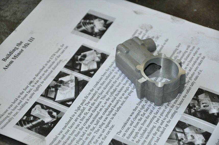
I am very disappointed in this. The 2.5mm tapping drill (M3 not 6 ba) just drifted all over the place and while drilling met all manner of lumps and bump imperfection along with buttery drilling too, but the drift was uncontrollable. I made a 'drilling jig', a good lump of dural and drilled 2.5mm and made to suit the location bosses (male and female) of the crank case. The lugs are poor material, the main casting much better and machined well on the lathe.
It will all go in a box now and eventually I will order £67 of fresh castings and start again, but will get my friend to make a steel gauge plate jig i can bolt to the case and ends to get holes to match.
This drilling is very hard to align without a milling machine and being able to position the pilot in X and Y accurately, but could take them over to Phil and get him to drill them on his miller along with the cylinder head bolts too.
I'm too embarrassed to picture the mess...
Will re-open this thread when I get fresh castings.
-
Terrible day on the engine today.
Scrapped all 3 castings trying to get the screws to line up, utter shambles.
At £67 for a new set of castings, I think i'll throw the towel in as I can't think of how to drill the case holes accurately with what I have.
I think you need a milling machine to index the holes and drill accordingly.
The cast lugs are partly to blame as they do not align to the main case well, 3 may be in-line, but the 4th is miles off etc. The rear cover can only fit in one place, and the lugs simply do not align, but the castings are like that everywhere.
Wasting time and money, so will revert to what I'm used to!
-
 1
1
-
-
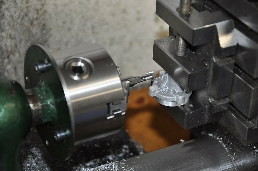
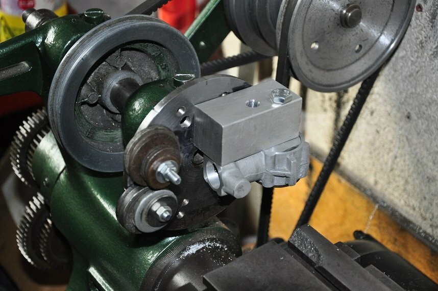
Had a great day in the garage today making lots of casting swarf, but good results with only one very near cock-up but i dodged the bullet by luck alone. Lots of pics:
Plan was to machine the crankcase casting, front casting and rear all bar the attaching screw holes, still awaiting my £15.75 pillar drill for that.
Finished the exhaust port inside and out and machined the small engine mounting pads, far to small, so was very minimal in my milling.
Spent a lot of time getting parts to fit into my tiny chucks, but got there ok.
The front casting was dead easy, the casting remarkably true, so all machined and reamed, bushes over the weekend I hope.
The rear cover was a pain. It is 'just' too big and lumpy to get into the 4 jaw, so had to chop the bulk of the venturi cast feature and will make a brass substitute and epoxy it in place into the plain hole I've drilled.
The spot facing of the attaching screw hole pads was awkward too as I could not cut them by turning, only using the devilish compound cross slide, but got there.
I made a mistake turning down the rear casting to fit the case, but had left some final material to cut so mamaged to get a nice fit after all, much as the front one is.
The matching of all these features in the casting is laughable. Might file some once screwed together to get most to match, but probably will just leave them.
All the pics:

-
Thanks for the support!
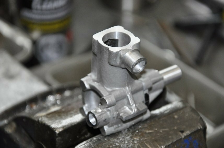
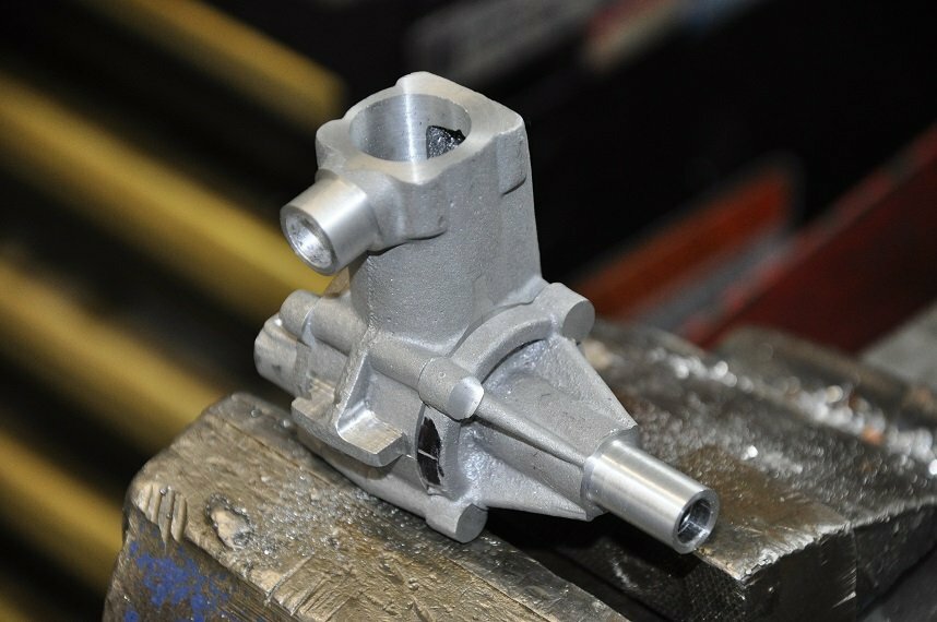
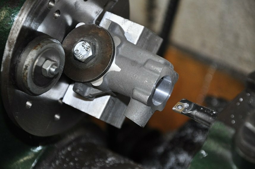
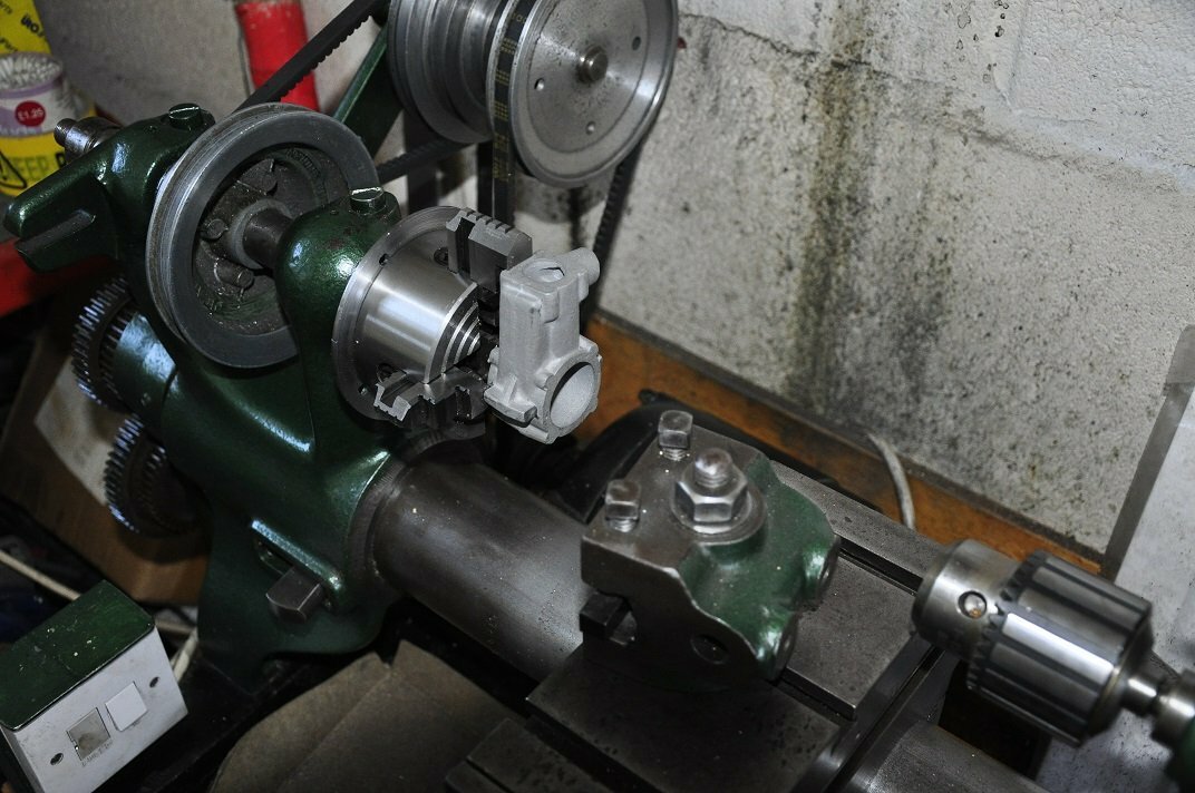
Ok, a few more hours in the garage today.
Today was far more fathoming out how to hold the main casting than machining it.
This lathe is small so has small features. It came to me with a reasonable 'home made' face plate which is the chosen mthod of holding the casting.
However, the 3" angle plate I now have is HUGE and weighs a ton, I would never balance it out for cutting, so used a nice piece of extruded alum alloy to be the substitute for the angle plate.
This all worked out great and with the instructions to guide me managed to get the cylinder liner bore all done and re-jig the same parts to align the exhaust stub pipe ready for machining tomorrow.
Hope these pics will speak a 1000 words:

-
 4
4
-
-
Not sure if this is going to be a bit boring, but i am sure i will need some advice along the way from you!
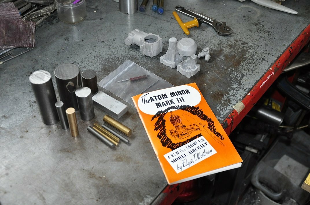
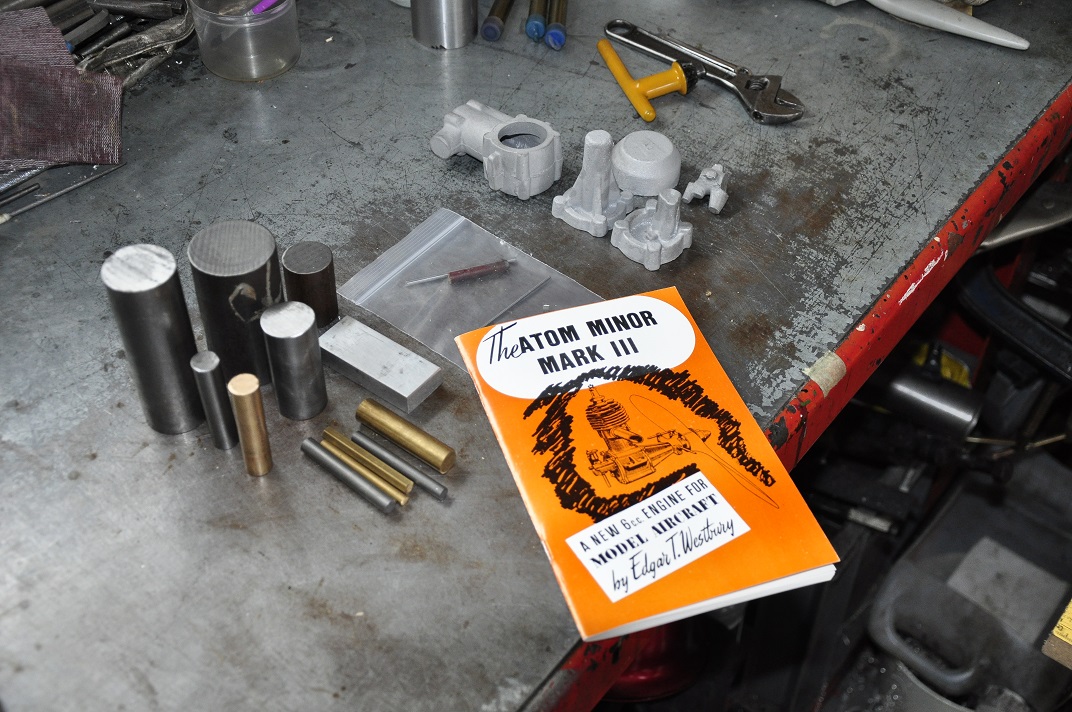
Having built the Hemmingway Sparey 5cc diesel (still unfinished business until it runs) I thought another trickier engine would be the ticket to a few more sleepless nights.
Thus I bought a Hemmingway Aton Minor Mk3 box of materials, the large parts/GA drg and the book written by the designer on how to make it.
The book is great. It seems he wrote it just for new-comers like me so I'm following his advice as well as watching the You tube episodes of Paul's Garage Projects.
I will be using the Drummond round bed lathe and the Myford compound slide but have just invested in my first precision pillar drill, all fresh and new from China for £15.99.
I have a new small capacity 240V piston drill that will fit, so all those case screws on the Atom design should be true.
I've treated myself too with a real parting off tool and a small angle plate to help making the slightly awkward crank case.
As i type this, the main case has been faced to 1" width and looks good, the bore for the cylinder is next which needs the angle plate on the face plate I have.
The crank casting only just went into my 3" 4 jaw chuck and was looking very precarious, but with light cuts it was good.
If the regular watchers are thinking, "oh no! not again" let me know and I'll reduce the thread to simply cries for help along the way.
I WON'T be offended.
-
1
-
-
Rich:
Yes, assembling the engines, set up and getting them to go. Not always straightforward!
The Atom Minor is a Hemmingway kit, so cast case parts and head.
Casting is surprisingly good, better than the Sparey kit's casting.
Jon:
No, the CP slides back, no 'crack' to a decompressed position.
When I made the head I used an M6 x 1.00mm pitch thread.
The engine uncompressed to engine fully mechanically impacted to the CP is a radial turn of about 100 deg of the screw.
Through all this I feel the engine should start to some degree, but there is nothing.
I can't touch the engine now for a few days, but will try later again this week and report back, esp if it starts!
-
To respond to these thoughts (of which I am very grateful):
No video of the ;action' but i will try to express them
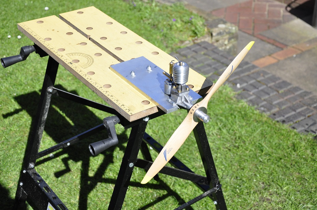
Engine on a stand, 16" prop and a length of broom handle to flick it over to save my old fingers.
Fuel is MT1000, sure smells of ether!
Prop tight on the crankshaft @ 2 O'Clock and the piston right up to compression, maybe 15 deg BTDC.
Sharp flick over compression is the technique.
Neat fuel on the ex ports with piston at BDC, rotate to 15 deg BTDC and flick. There is the sharp 'pop' you get from these engines and the prop spins round to 15 deg BTDC and stops.
The compression stops the flywheel effect of the prop going over compression again.
I repeated this action a 1,000,000 times varying the compression, the prime and the addition of old Easy-Start spray and noting changed except the snap of the pop, no firing nothing at all, 'lifeless' you might say.
To piston/cylinder leaking:
Prime the engine via the ex ports and rotate the prop to compression slowly. Ease it over tdc and round again. Just on tdc and holding that position small bubbles form just by the ex ports the neat fuel leaks by the piston skirt.
Flicking the prop as you would there is none of this bubbling. The action is too quick.
I am beginning to think I have over primed this engine and flooding it all though all these attempts; as previously said a few drops only, i was giving it far more than that.
A friend I spoke with (an experienced model engineer) had a glow engine in his workshop in pieces.
The piston would not pass into the top of the barrel by hand, and the bore has a taper of 4 thou, wider at the base.
Possible actions once I get back to the Sparey will be to make another piston with 'interference' fit at the TDC of the bore, probably mild steel as I can finish to size this easier than cast iron. This would be to test this 'tight at the head' theory.
As to the Atom Minor:
Started to machine the main case today which went really well, quite surprised myself!
Not sure there will be too much interest in a build as it shows my low skill set in these matters.
I am far more more at home building big tuned 3.2 litre Porsche air cooled engines!!
-
Thank you Rich.
The fuel is the MT stuff, 1000, in a white tin.
Must admit to using more than a drop of fuel to exhaust-port prime, but did not drown the engine.
Tried a mix of easy start (old can of it) and the fuel, but to no avail.
It is on the shelf now, but I'm sure i will re-visit it before long.
Started the Atom Minor today and did some good accurate machining too!
-
1
-
-
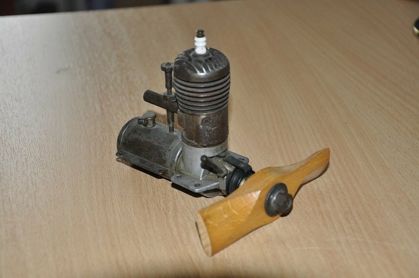
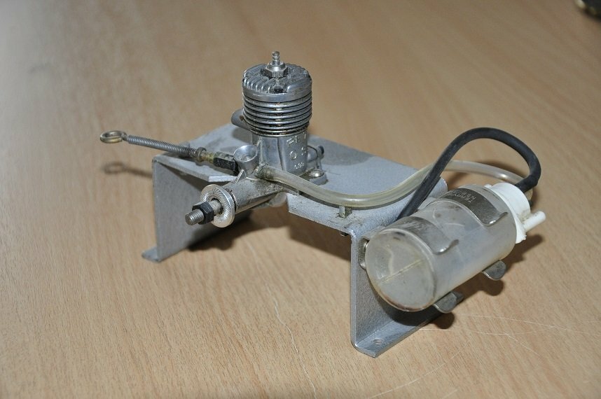
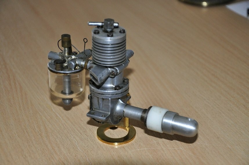
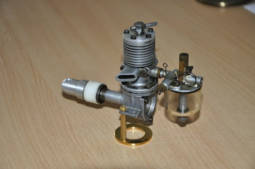
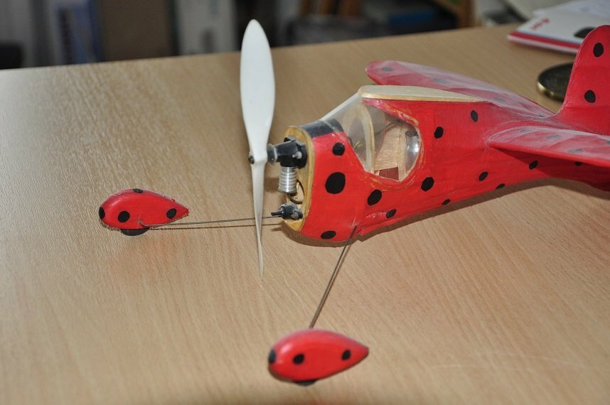
These are the engines in my 'collection'. Bought when found cheap or bought with my heart, not head!
In order of the pics below:
Autojumble find for £5 40 years ago:
OS PET from my schooldays:
Bought for £70 when on hols via ebay some years ago:
My favorite find for £18:
My very first ever ebay buy, a delightful CO2 in the model, i have the wing too:
And the last one not pictured, but a new PAW 1.5cc still boxed, never run.
-
The engine on the right I found in a local antiques market for £18.
It is a cracker, moves freely too.
was going to get it going, but was bothered it would fail and break.
I asked on Rome about what is was, but long forgotten now!
Im sure the above is right.
Ill gather my other engines together to be of more interest.
-
Should have said the exhaust ports.
-
Yes, I am disappointed in the lot TBH.
I've battle long and hard on many restorations and won despite lots of issues, but have little interest in fight this out.
The project was more to do with the old lathe than the engine, but a runner would have been good.
A new ultra tight fitting piston would possibly answer your thoughts?
There is absolutely no activity in this engine, not a pop or anything suggesting it will fire, just nothing.
Must be fundamentally wrong somewhere in what I've made.
When the piston is at BDC the piston top is flush with the ports.
-
I smell of ether...
I smell of blood sweat and tears...
This engine (if I dare call it that) will not start.
both wrists hurt from trying and the wood prop looks like firewood.
I have decided to leave it for a while or for ever (preferably) and let it sit on the shelf and remind me that this is a Bad Day.
Found a fancy brass engine stand, so this is the final picture:
-
Yes, good advice.
I used this method on a 1949 Terrot French motorcycle 2T petrol I restored a few years ago to good effect, but not a tiny oil burner.
The wood prop has started to splinter where I've been using the broom handle to flick it over. The handle has a plastic protective sleeve which is intact!
Not sure this is all worth it, but will try harder this weekend.
Funny how the distinct smell of the fuel brings back memories from 60 years ago!
-
I think I will rig up an electric starter using a pistol drill running anti-clockwise and see if fast repeated turning over will get it going.
Not even a good dose of Easy Start helped.
Another piston sounds boring, but maybe I'll try again.
What i don't grasp is that I can take the compression to very near hydraulic lock down to 'zero' and nothing happens, you just loose the 'pop' as the piston goes over centre.
-
This will make a nice paperweight!
It will NOT start no matter what I do or try.
Do not feel inclined to keep on trying as I feel there simply is not enough compression to get to the ideal mixture.
In the meantime I've bought another design to make on the Drummond. It is a 1933 design spark ignition, 6.3cc and more complex to machine.
Tinkering is better than using.
The audience has all but dissipated now, so thanks for following the adventure, and a special thanks to those who have guided my progress on my first engine.
I won't do a thread on the next engine.
73T 911 Cou
.JPG.d0f4c0aba6170dde192b3eb1ccce7784.JPG)
.JPG.d0e966c0bb7d9c35478f0dd71ab62a3f.JPG)


.JPG.488261243a9539be2714172245b903c6.JPG)
.JPG.ec15b6a0b575cadaa5c5babf77a372a6.JPG)
.JPG.144797edf9982e4383c7af2c8ec0bc27.JPG)
.JPG.5de69c82744b3f712a75abc8a67192d0.JPG)
.JPG.7bdee6d47b681d020b4892eff3b43e9a.JPG)
.JPG.332ad5c59c661501762cf37ed731418b.JPG)
My Atom Minor build
in IC Engines
Posted · Edited by 911hillclimber
Thanks for the post, and you are right.
Still trying to work with what I have.
The drill jig I have made is surprisingly accurate (it seems) and is 6mm thick so acting as a drill guide, not that robust but good enough I hope to drill just the holes for this set of castings.
Really busy over the weekend, but will try to save the other castings with this rod if they prove to be compatible.
The drill wandered off when drilling, the drill would progress well initially then I hit hard 'stuff' and the drill (2mm dia) would simply ride to one side of the hard inclusion.
This was only in the end casting mounting bosses.
The rod supplied via ebay is Alubuild 300. The description reads it should do the job!