


Disciple of Autogyros
-
Posts
98 -
Joined
-
Last visited
Content Type
Profiles
Forums
Blogs
Gallery
Calendar
Downloads
Posts posted by Disciple of Autogyros
-
-
Hi Rich,
Thanks for your reply. I did wonder if the thrust line was a bit in the high side. If you do come up with any ponderings, please let me know. In the mean time I will confine myself to little hops. Having said that the weather today was very wet so no hopping.
Hi Steve C
Thanks, I did have an action man initially, but it was the wrong scale. I'm considering a carved foam figure like Rich did of Ken Wallis. I suppose a Sean Connery foamy would be the next best thing
Cheers
Mike
-
Hi Rich,
At long last.....It's finished. Thanks for taking your blades to P/Borough for me to copy and your support through this build. if anyone else is interested:
Blade length (total) 726mm
Length to bolt hole 720mm
Width 60mm
Thickness 6mm
The hang angle is 17 Degs at AUW with a 2200mah 4S battery.
AUW 1484 grams
Rich,
I've mapped the hang points (top of nose wheel under the fus and top of mast) to get the C of G, against the thrust line. The thrust line is 40mm above the C of G. Do you think this is OK? if not, any suggestions?

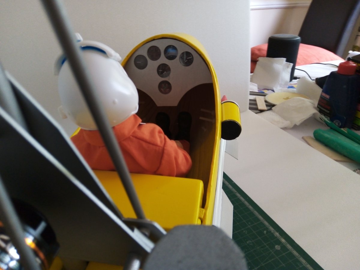
Hang test photo (a bit bleary though) 17 degs
Here's the finished Little Nellie.
I have to say... "I'm pleased" will try some test hops (not flight) tomorrow.
-
Hi Murat,
Thanks, but I wish they were 3D printed!. They took ages to make. The flame throwers were made from plastic overflow pipe with wine bottle screw tops hammered into a cone shapes for there front, the flame thrower exit was made from cone shaped depron. The rockets pods were made from a Berroca Orange tablet container cut to size with the rockets (tips only) made from wood dowels covered in a strip of white insulating tape and the tips painted red. The guided missiles were made from thin cardboard sheet rolled to a tube with 1/16 ply for the fins, and a balsa nose cone. All the white bits were spray painted, they needed several coats. In all it took a couple weeks to do.
If you/anyone following this thread has a 3D printer....use it... the accessories were a pain to make.
-
Its been very slow progress, but the paint job is done. there is still a lot of building to do though.

-
 1
1
-
-
Hi Rich,
I'd be interested to see a video on calculating rotor loading as I'm sure others would too.
Cheers
Mike
-
1
-
-
Hi Rich,
I'm sure I'm not alone in wanting to see the build to completion. The Twister looks really good and the name is very apt. A potential mass build I wonder???
I look forward to you getting to the blade set up in particular as I hope it will give me some tips for Little Nellie.
Cheers
Mike
-
Hi Rich,
Thanks, it's slow progress at the moment. Can you give me an rough indication of the weight per blade I should use?
Yeah...I'm not very impressed with this platform, the previous version was clearer and easier to access
Cheers
Mike
-
Hi Rich,
Thinking ahead regarding the blades, I read somewhere that 2 bladed gyros need to have tip weights? is this correct? also do the blades need shims for negative pitch just like 3 bladed models?
Cheers
Mike
-
Hi all,
Now the weather is warming up I'm back on the Little Nellie case and can work in the garage without freezing my extremities off.
The fuel tank is now completed. It's made from pink foam and depron then glassed. I've added captive bolts epoxied to the foam for fitting to the fus. The next job is the prep for painting and making the weapons.
-
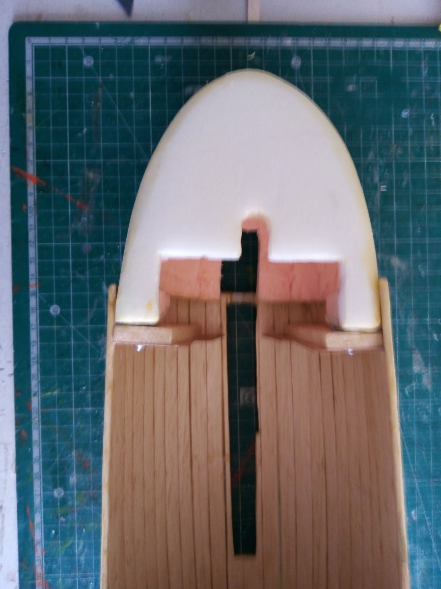
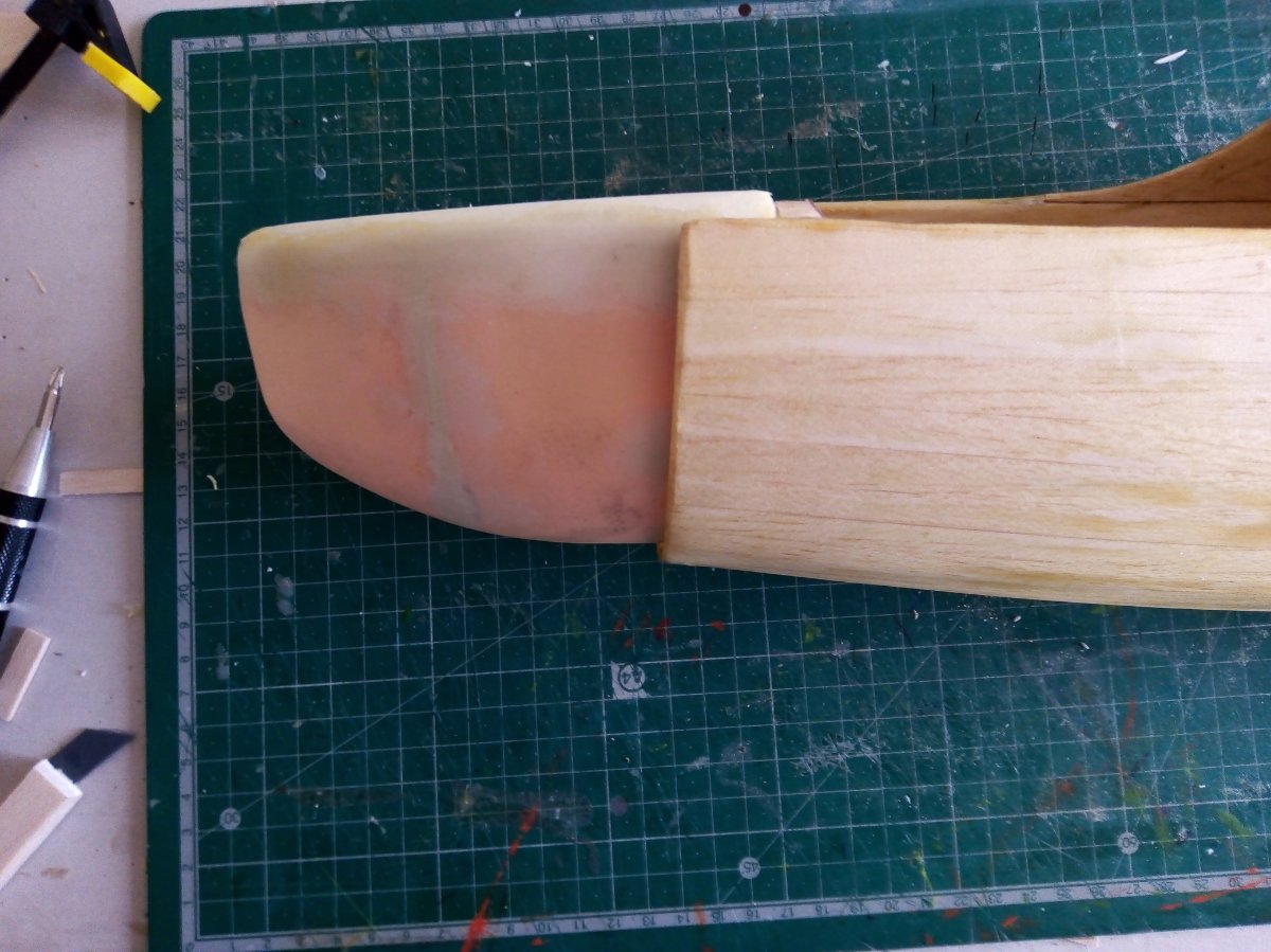
The pod/ fuselage has been a bit of a challenge, as I don't have enough suitable foam to carve it from, so I used balsa planks over a some formers. The end result is not great but I can live with it, and it's light enough. I still need to rub it down a bit prior to painting.


I carved the nose cone from the last of my pink foam stock. I think I'll have just enough to carve the fuel tank and rotor head cover. The gaps in the balsa planking was filled using a mixture of Talc and non shrinking dope mixed into a paste. The resulting filler is easy to work with and when cured easy to rub down to a very smooth finish and smells great (bonus), I then glassed it, but as yet I've not completed the pre painting prep.


Glassing isn't one of my strengths, so it needs some rubbing. I may be able to live with it though. We'll see.


-
I trial fitted all the main frame components but it's made me have a re-think on the position of the servos. As they now are, there will be some interference between the motor mount front plate and the servo rods to the head Tee bar.


I've incorporated a kind of suspension to the rear wheels by inserting some silicon fuel pipe (as a dampener) inside the upper carbon tube with the lower carbon rod acting as a kind of ram. It might work!


-
Hi Rich (and Tim)
No worries, I've not done any blade work as I've plenty to get on with. Like you I'd prefer not to have a tail plane but unlike you I don't have your skill and capability to fly tailless, so I may add a tail to help with stability.
I did a comparison with the 1:24 scale Airfix kit for some initial guidance. Converting the measurements to 1/4 size I get a blade length (tip to bolt hole) of 670 mm and width 44 mm, the width does seem a bit narrow though? That would give a rotor diameter of 1438 mm (or 56.5 inches). I have no idea how much this is going to weigh at this point so I think I'll leave the blades for now but your wisdom would be welcomed.
-
Hi Rich,
Next question....Re the blades, what length (tip to bolt hole) and width?
Sorry to be a pain.
Cheers
Mike
-
Hi Rich,
Thanks for the photo and info. Is Flapping Plate the proper name, or did I catch you on a bad day?

Mike
-
Hi Rich,
Thanks for the video and reply. I saw a DVD about Ken Wallis, he had a remarkable life, was very lucky through the war years and a very clever man. It must have been a fantastic experience meeting and talking the man.
Re my question, I just wanted to know if I was on the right track with the rota head dimensions as compared to your Little Nellie. I've not made a "two blader" before so it's a bit guess workish.
Cheers Mike
-
The rotor head plate for the blades is 1.6mm GF. I made a guess at the measurements for this. It's 50mm wide and 174mm long. The pilot holes for the blade bolts are 60mm from the centre. The flanged bearings has 11mm flange, 8mm o/s dia and 4mm i/s dia. The bearing plates are 1.6mm GF.
Rich,
Question, do you think this is about right?

I also added a 3mm ply spacer for both baring plates. One can be seen below


Trial fitting all the bits, it seems to work ok. The bearing spindle is made from 4mm silver steel. I think I'm going to need a longer one though.


Edited By Disciple of Autogyros on 29/10/2020 16:27:52
Edited By Disciple of Autogyros on 29/10/2020 16:52:39
-
The engine/suspension mounting plate is made from 1.6 mm GF. It's bolted to the carbon mast. To prevent the crushing effect on the CF tube when bolts are tightened, I inserted 8mm (approx) wooden dowel inside the CF tube at the point where bolts go through. The engine stand-off's are made from 6mm Ali tube and the engine mount is made from 1.6mm GF.


-
I had to make a change to the tig welded section of the undercarriage as the angle was too high so rather than start all over, I epoxied half of a universal joint inside each side of the crutch so it acts like a hinge point with some Ali rod, which will be inserted within the undercarriage carbon tubing. I'll be able to reduce the angle of the undercarriage struts and fix in place when fitting the suspension arms.


Edited By Disciple of Autogyros on 26/10/2020 18:11:16
-
Hi Rich,
Thanks and will do. As hanger queens go, it still looks stunning and as it happens, this view shows the underneath which is helpful for me.

Just checking, the reference to " any of the mods see this"..... I've assumed that message for the thread moderators?
Cheers
Mike
-
Today, I've been working on the mast head.


The universal joint (from e-bay) has an 11mm outer with a 5mm hole at one end and a 4mm hole at the other. The 5mm end has a bolt attached which was then epoxied through the aluminium sleeve (made from the 12 mm ali bar) into the 10mm carbon mast tube. The mast tube is 330 mm long. I may shorten this later in the build though.
-
Hi Bas,
Thanks for the encouragement, I'll try my best.
Mike
-
These are the servos I'm proposing to use. I bought them a long time ago for another build but never used them.

-
Following Rich's build I started with the crutch. Its made up of 12mm aluminium rod, drilled with 10mm hole to take the 10mm carbon tubing. A friend at my club arranged for the Tig welding which was very handy.
As a guide, most of my photos are taken on the cutting mat. For scale/dimensions the squares are 10mm


The servo mount is made from 1.6mm fibre glass sheet. Can you spot the misaligned hole in the servo mount?

Edited By Disciple of Autogyros on 22/10/2020 14:34:33
-
Little Nellie Resurrected
It's been a while since this thread last updated, so here goes.
For my winter project I wanted to build a Little Nellie, but after spending days scouring the interweb for plans, drawings, top, side and front photos from which I could build a model to no avail. I even contacted the Shuttleworth Collection but they were charging the entrants fee (which I was more than happy to pay) with the additional fee of a supervised photo session for £65.00 ph plus VAT. That was a tad too much for a pensioner. So instead I bought a cheep 1:24 Airfix kit from which I could calculate a 1/4 sized model.
I came across Rich's build thread and videos and contacted Rich to check he was happy for me to add my build. In case anyone want to use my info, please be warned, I no expert in build or design, however I'm good at crashing! and look forward to any helpful feedback during the build. Here goes....


007's 'Little Nellie' MK II
in Autogyros
Posted
Hi Steve,
Apologies for the delay in responding. That sounds like a great idea, it had never occurred to me that this could be a solution. I'll give it a try and report back, though it won't be for a few weeks as I've got too much on at the moment.
Thanks
Mike