
David Wilson 25
-
Posts
126 -
Joined
-
Last visited
Never
Content Type
Profiles
Forums
Blogs
Gallery
Calendar
Downloads
Posts posted by David Wilson 25
-
-
Bob, this thread seems to pull all the unfinished Deagi Spits out of the woodwork! It so happens I was contacted from the Irish forum (http://www.gliderireland.net/) re the magazine build plans, so DM me your email and I'll make them available to you.
-
Have to agree with some of the views here.
If it's a "professional" grade job; e.g. advertisements, flyers, journalism, I detest the superfluous apostrophes. Their entire business is built on the written word. They ought to have a good standard of grammar and punctuation.
I also can't abide the proliferation of "aircrafts" or the adding of "s" to words which remain unchanged as plurals. Perhaps a new one to annoy others: "myriad". Plenty misuse the word in myriad ways.

Having said that, on a forum, not all will be fluent in written English, so I let it slide.
-
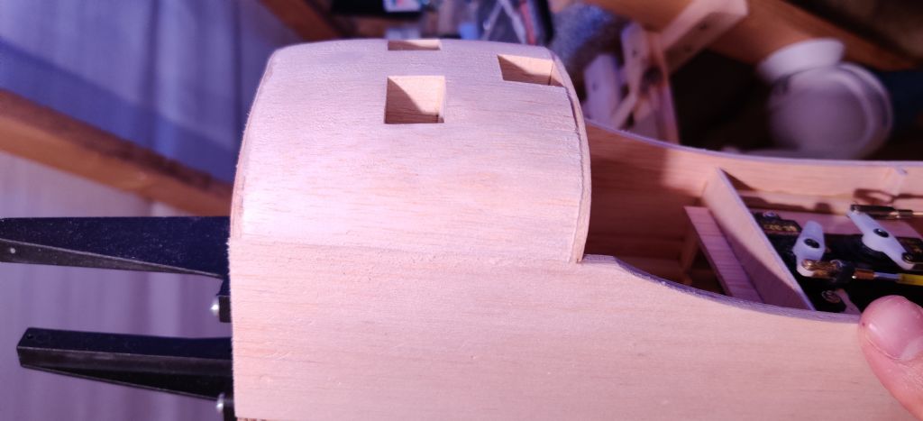 I can't believe that this Spitfire still isn't flying almost 2 years after I started! Even the lockdown and the benefits of "work from home" haven't quite provided the additional build time I anticipated... Life does have a habit of getting in the way of more enjoyable pastimes...
That's not to say that I haven't been getting anything done. Unfortunately, working in the attic is impossible in warm evenings; it's stifling.
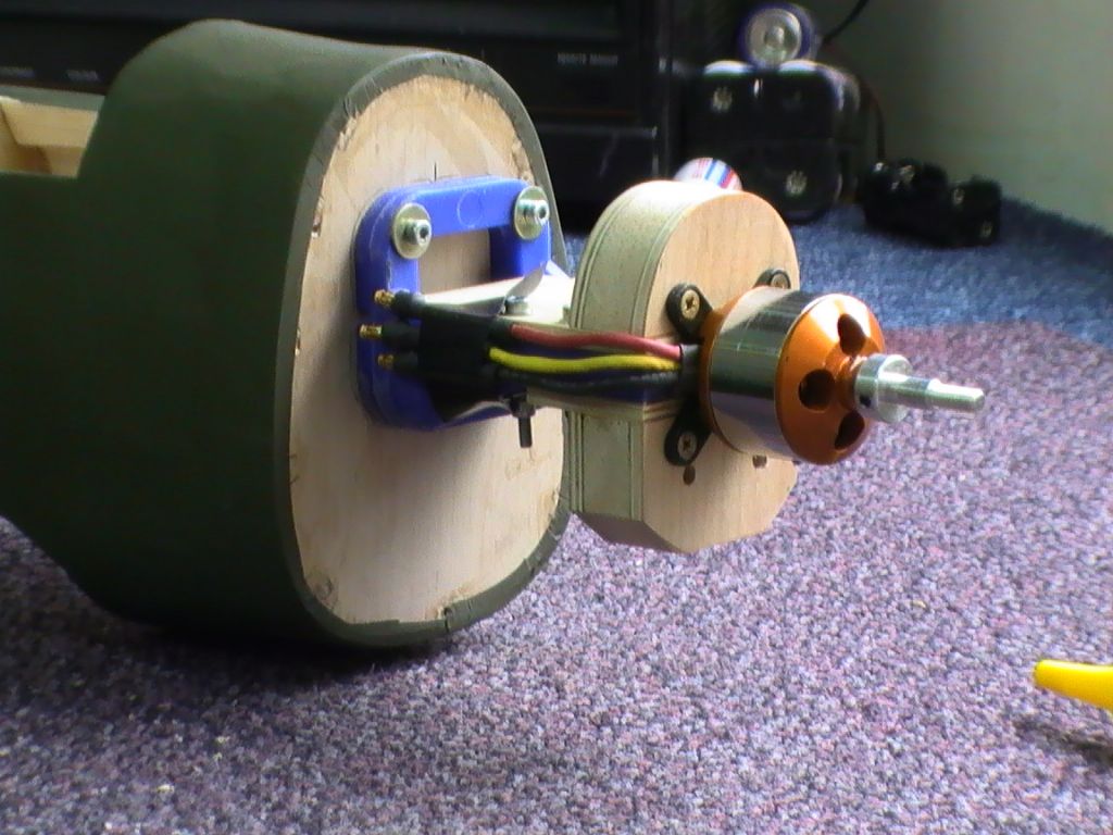
Unfortunately the motor mount I created wasn't quite right; the firewall wasn't corrected properly and there isn't enough space to adjust. It looks like i'll need to procure some M4 threaded rod and take that path.
On a pleasant note, the pull-pull rudder cable has been installed and the appropriate slots cut. The rudder snake is routed and suitably supported. All hinge slots are cut and moving freely.
-
Got a bit further anyway...
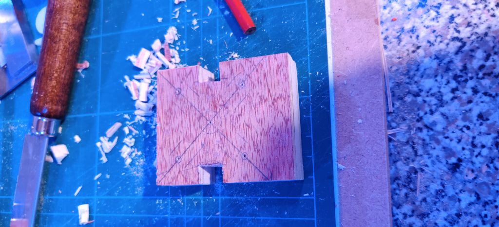
"False firewall" motor mount created. Though going by Dwayne's photos above, I'd be better cutting in two and gluing to ply so that it can be bolted to the IC motor mount.
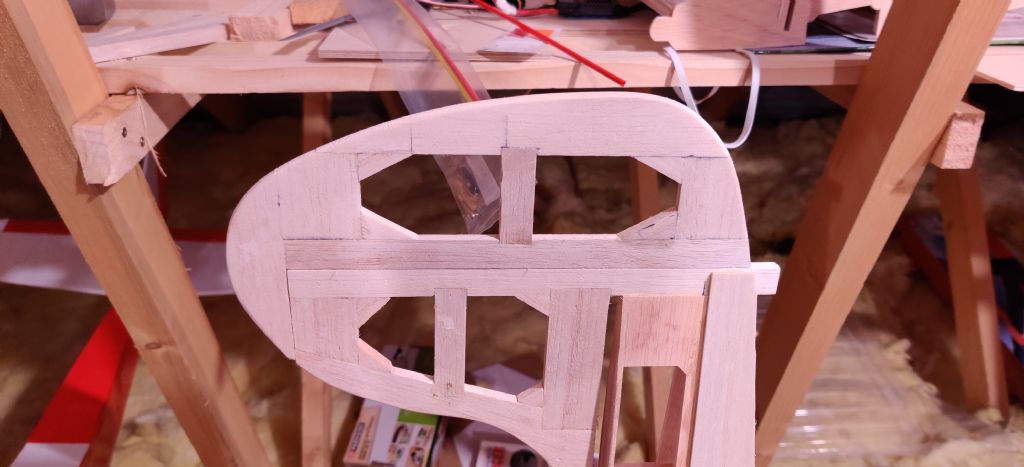
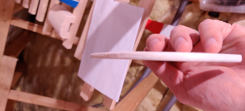
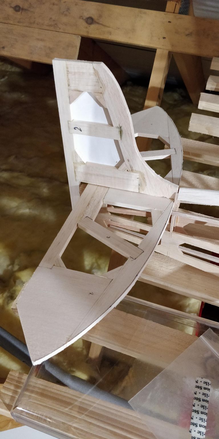
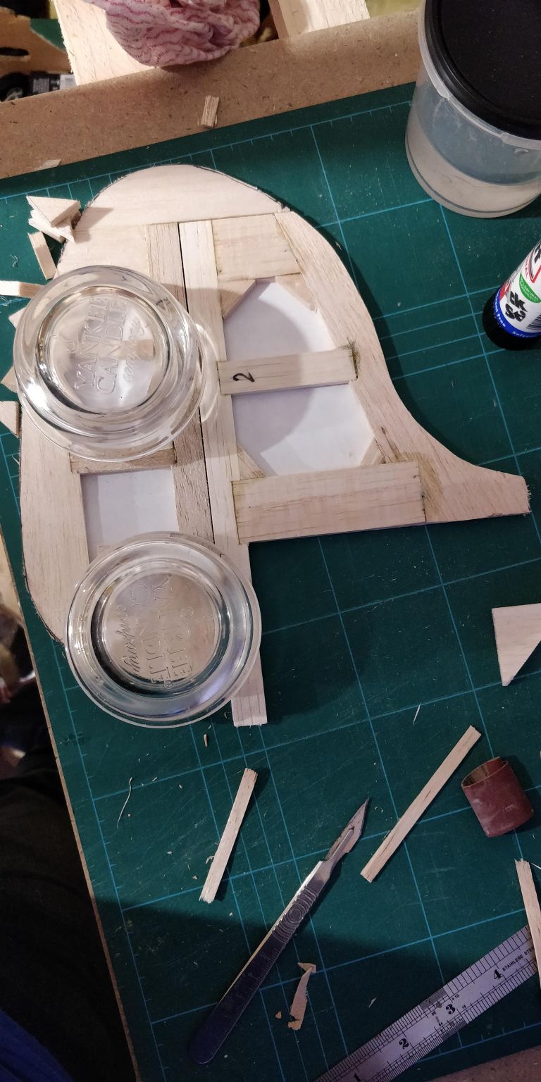
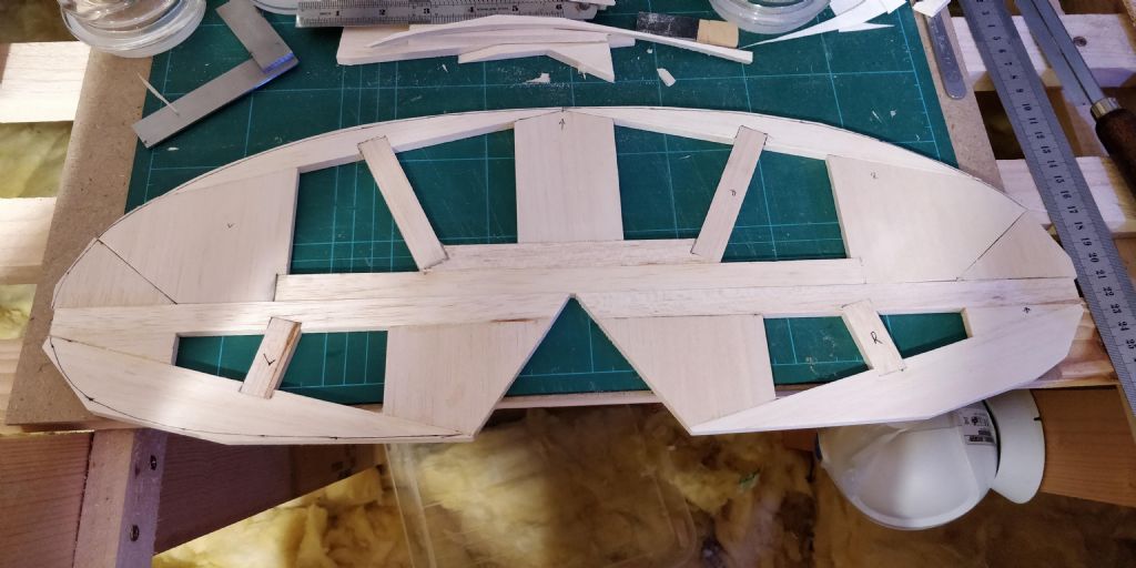
The tail is progressing as well... I did have them roughly shaped; they're now sanded to shape. I'm happy enough bevelling a straight edge, but the constant curve of the fin, rudder and tailplane is a bit of an extra challenge... Any tips?
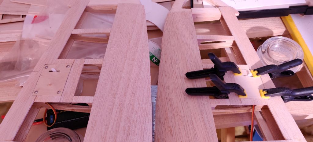
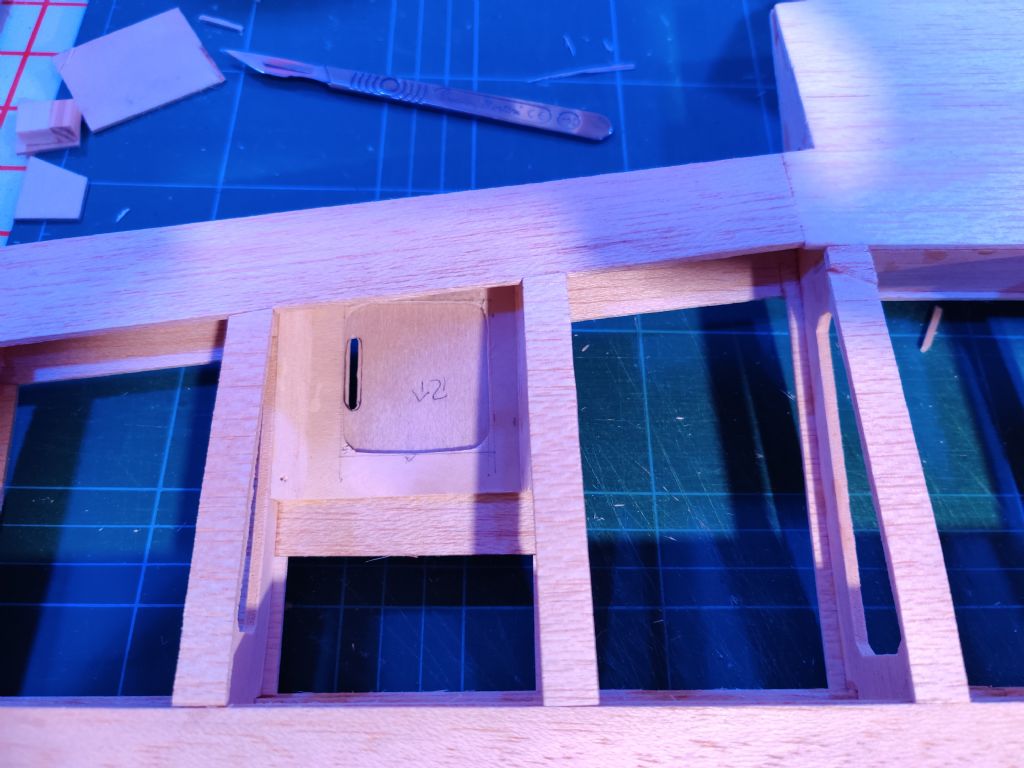
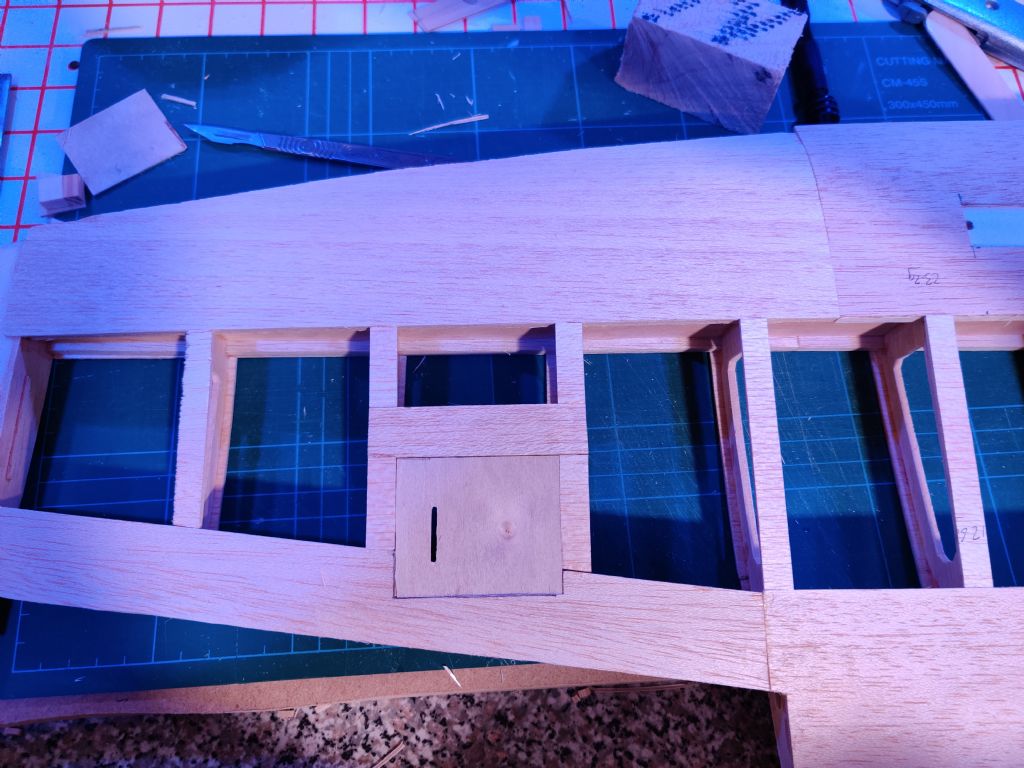
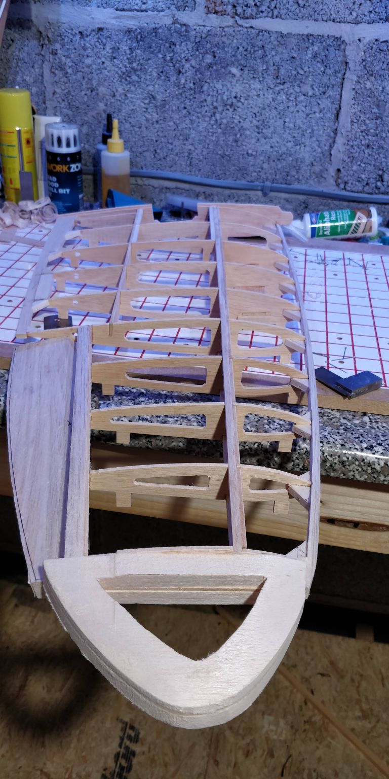
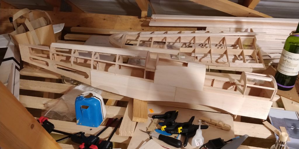
Both aileron hatches are complete, with the servos fitted to make sure there was clearance. Note to self - build the servo mount BEFORE creating the frame! Checked clearance of the servo arms by moving the servos with a servo tester... Snug, but free moving.
Edited By David Wilson 25 on 18/05/2020 20:48:48
-
Posted by Dwain Dibley. on 11/05/2020 12:52:13:
Nice progress David. Your rib cappings have the grain across the rib, I would have had the grain along the rib for strength, NOT a criticism, just noticed, that's all. Can't remember what the plan said now. LOL
Any way, it's looking great.
Do I detect the classic "feedback sandwich"?
 No offence taken.
Plans said grain across the rib; I wouldn't have liked to try and curve along the grain as the balsa provided was rather stiff! I suppose it was aimed at a clueless first time builder. I didn't think about it too much at the time.
-
-
Posted by Dwain Dibley. on 20/10/2018 19:16:26:
Just to show anything is possible........How about this one, that replaced a chunk of 3/4 inch roofing ply.
D.D.
Dwayne, it's been a long time getting to this stage, but even in lockdown I'm not getting the time to build the spit...
Decided not to go down the route of building a motor box; kept messing up the squareness of the corners. Besides, I think the above offers some adjustability? It's just balsa sandwiched between 2 layers of ply? The "legs" to fix to the motor mount are just laminations of ply?
I have the two wings 90% done; servo covers sized, but need to create the mounting fixtures. Each wing is 325g +/- 5g (11.5oz +/- 1/5oz) which I though is reasonable. Photos to follow.
-
Success! Needs throttle input before the gyro becomes "live".
Though, even with the gyro "off", it still seems to have a little bit of input.
 Still, I'll have to get wind under her wings now.
 -
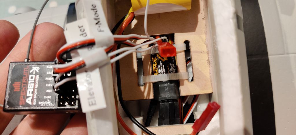
Hopefully the pictures above show some of what I've tried to do...
The "Gear" switch is the only 2 position switch on the Tx.
Inhibit all switches EXCEPT "gear" and ensure the "f mode" servo is plugged into the "gear" port on the Rx.
Sounds like that should work, right?
Except, nothing.

-
-
I've checked that all the necessary switches are active. I've also set so that only the gear switch is active, rebinding each time.
Everything shows full travel and correct motion on the TX screen, but nothing seems to happen with the plane?
With the other Rx, when I move the plane, I get the corresponding opposite motion with the stabiliser. Nothing happens with this one.

I'll grab photos and upload.
-
I got the HK Skyraider for Christmas and am trying to set it up for when the weather finally breaks, but can't seem to get the stabilisation to work.
The manual "helpfully" states to use a 2 position switch (using Gear) but nothing happens in either position. Also tried using the AUX 2 channel (3 position) but still no joy.
I previously used a ORX receiver with integrated stabilisation which works ok, except I can't turn the stabilisation off...

Has anyone any experience with this kind of issue that can offer any advice? I've tried setting trims, travel etc with no joy.
-
Thanks Alan for the offer of posting me materials! Turns out I'm headed to Dublin today, so a call into radiocontrolledshop.ie is scheduled!
 Needless to say, more than a single sheet of 1.5mm ply is likely to be purchased.
  Nothing additional will be declared to the "Financial Controller" otherwise she'll not buy me a plane for Christmas...
Unfortunately no new pictures to share, but between everything else going on, I've just had the opportunity to glue on some of the wing sheeting. The port wing upper surface is almost done and the s/board is started. I might yet get it completed this winter.
-
Unfortunately, I live at the other end of the country, so all those are at least a 2 hour drive. I'll probably call to Mid Ulster Models next time I'm up at the parents, or get them to post to them.
Even ParcelMotel isn't of benefit as it still needs the parcel to be shipped to Northern Ireland. An Post's AddressPal is probably the best option; they use a central UK delivery address. I'll just need to order pre-brexit...
-
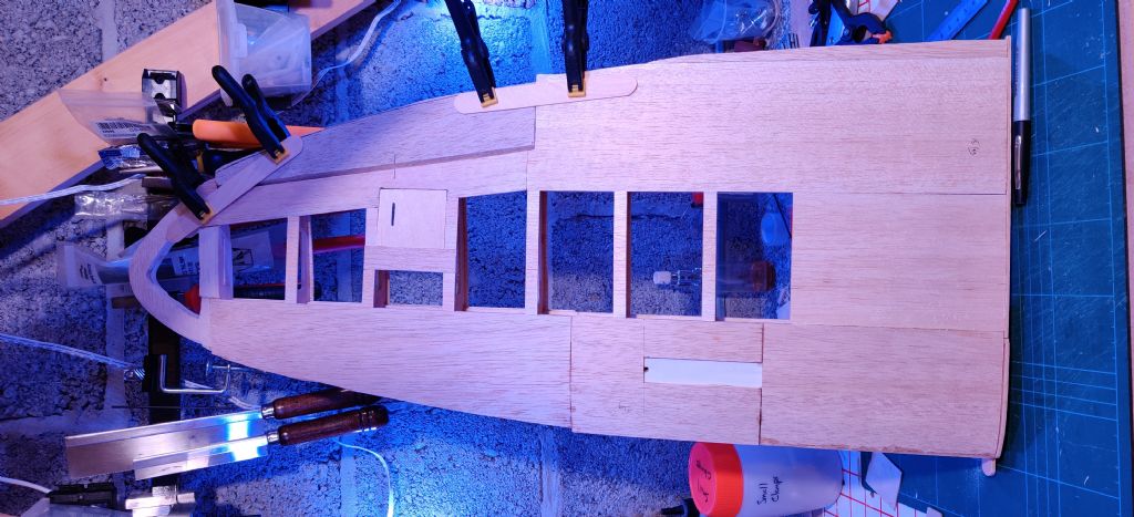
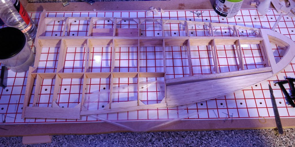
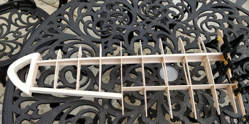
After a hiatus (holidays & too many things around the house), I finally got a little more done. Both wing structures are built and just need to be sheeted. I put it all off for a while beacuse I just wasn't in the mood to sand off several millimeters of balsa from the wingtips, so I roughly shaped the ailerons instead. They're still "friction fit" at the moment so I've a it spare to play with once the sheeting is on.
Just realised that I don't have 1.5mm ply to create the aileron servo mounting plates, so went to SLEC's website... £13.50 for the few bits I needed and £19.80 shipping!
 How I hate the couriers shipping to Ireland (North or South, makes no difference)!
The fin, rudder, tailplane and elevators are also built. Fin is now fitted, but did a dry fit to see how things stood.
Since I started building, I got myself a razor plane and two razor saws; I don't know how I managed without them! I'm finding my joints and general build is noticeably tidier as a result.
Having moved the servo plate to fit the battery in, the distance is now too great to use the supplied balsa dowel for the elevator control... I assume a snake would suffice, once securely attached to the fuselage formers? I doubt that a pull-pull system would be advisable especially when it would need to rotate through 90º?
-
Cheers for that Dwain! That's like the method I've seen described elsewhere and seems like a stronger method than simply mounting to the balsa sheet.
I've been busy working and not posting... So I've managed to get a decent amount done; 20 minutes here, 30 there maybe twice a day, so the glue gets a chance to dry.
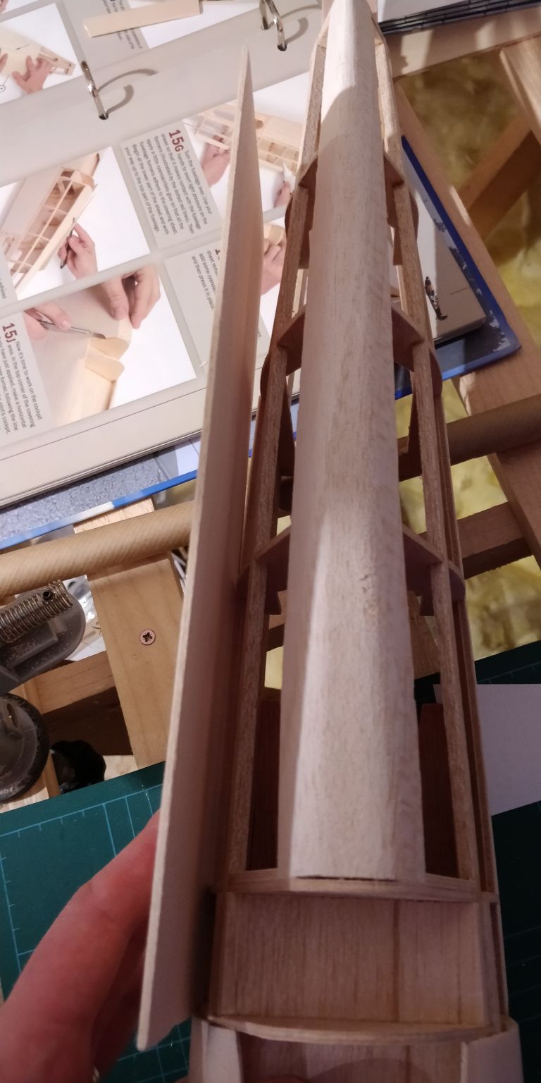
Rather than start on the fuse proper for sheeting, I started with the hatch. The instructions use CA for practically everything, but I've been using aliphatic resin instead. I believe it's a better option because it allows a little flex rather than shearing when stressed...?
That having turned out ok, I did the cockpit area. As you can see, the port wing has approached the classic elliptical shape. The starboard is at appox the same stage this evening.
Fitting the next sheet after the cockpit is going to be fun... There are two curves laterally and two vertically. To complicate matters, there's no room to clamp. The sheet is taller than the fuse; the excess is to be trimmed off once affixed. That approach precludes the use of elastic bands to maintain pressure if using aliphatic. I suppose... I could mark the excess and trim before fitting.
-
I felt like I needed something that would give me a bit of cheer/encouragement to actually see "progress", so, once the fuse was sheeted on the other side, she got set aside for a while. Just so I can let the servo question work itself out in my head. You can see the positioning of the servo plate in the centre.
In the meantime, I moved ahead and did a quick bit on the port wing (Note to self: Make sure and triple check not to build two port wings...).
I have to say, the little jig is a simple and effective way of ensuring the ribs are true. The rib to the left has a little twist of about 2mm, so I'll have to prop it so that it glues straight. I don't want to try the "ironing" trick as they're made from some sort of balsa ply and wetting is likely to cause them to delaminate.
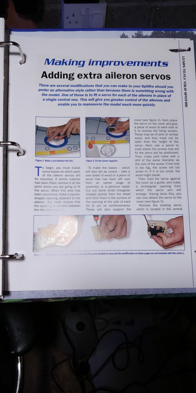
Because I can't do anything more until the glue dries, I had a nose at the "alterations" that're included in the folders that came with the kit; specifically fitting separate aileron servos. Usually, from build logs I read, it looks like the servo is mounted on a ply plate which are screwed into a hollow square glued between two ribs. According to the guide, it appears DeAgostini just mounted the servo on balsa and screwed into balsa triangles glued to the wing sheeting...

Checked my supplies... I don't have any thin ply.
 . I'll have to go get some. I'm sure it'll be months before I need it!
-
If I fit the servos from the top, then access will be tight, but achievable.
Fitting from the bottom will be through the wing mounts, so there's plenty of room there.
I'm trying to move the servos as far forward as possible to avoid adding extra weight, but haven't just got the hang of sorting out all the wrinkles caused by doing so.
And, even as I type, I'm remembering that with 10mm mounting rails, the servos probably won't need to be fitted "inverted". Photos to follow because it'll be too hard to explain!

-
After a unintended 6 month hiatus, I've got back at the building...
The was a bit of procrastination over the firewall; I finally decided to take a 5mm sheet of ply and sand it to a wedge to correct the thrust angle.
Moving on, some idiot (who shall remain nameless
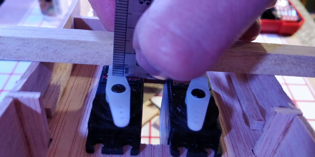
 ) glued in the servo plate in and didn't consider the clearance required for the servo arms. The hard balsa "rails" for fixing the screws to haven't been glued in yet, so I can still amend things somewhat.
The clearance between the wing plate and the servo control horns is about 4mm; I'd guess that should be sufficient?
I have thought about fitting the rails on the surface the servos are resting on in the photos and then screw them in from the opposite side; that'll give a few extra mm of clearance if it's required.
-
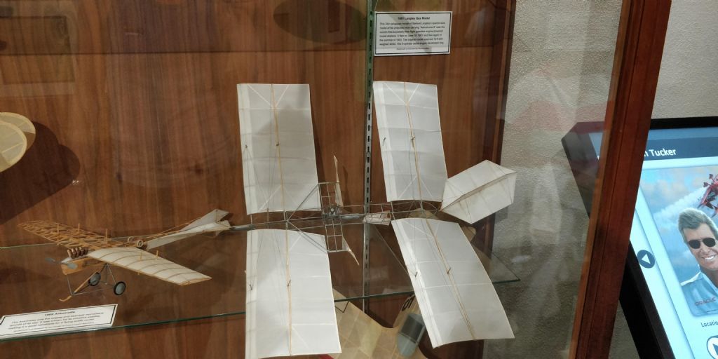
David, I can... Both models are on display at the San Diego Air and Space museum.
Top photo:
First successful radio control system
The 8 foot Guff radio control model won the Radio Control event at the National Model Aeroplane Championships for 1938, 1939 & 1940. It was a product of the collaboration of model builder Walter Good and his radio "ham" twin brother, Bill. This full size fuselage and it's radio equipment were built according to the Good brother's on original published plans
I don't see the plans, but a build article is here... Can't edit link on the phone, sorry!
http://www.theplanpage.com/months/2403/guff.htm
Bottom picture:
1901 Langley gas model
This 24" model of Samuel Langley's quarter size model of his man-carrying Aerodrome A was the world's first successful gasoline engine powered model aeroplane. It flew on June 18, 1901 and flew again in the summer of 1903. The original model spanned 12ft and weighed 42lbs. The 5 cylinder radial produced 3hp.
Edited By David Wilson 25 on 30/10/2018 13:34:36
Edited By David Wilson 25 on 30/10/2018 13:39:10
-
-
I've used zippys and never had any issues. Saying that, nowhere near that size, so my 2p is limited. 😉 Edit: gorgeous looking plane you're getting. Maybe one day...
Edited By David Wilson 25 on 22/10/2018 21:39:42
-
Overlander Thumper ordered from SMC today along with the ESC and other bobbins necessary to continue...
Might have gone for a bit too much power at 980W max. 😎 -
Your Spit seems to have dressed up and changed sides after the operation, Dwayne! 😂
I'm from the school of "build as light as possible and only as strong as it needs to be". Hence the reluctance to put in unnecessary weight. But... if it'll need plenty of weight up front to balance, then common sense dictates "make it functional weight".
Looks like I'll have to spend the cash up front and get the power system and mock it up. 😏









Amazon Prime Deals 2020 (Oct 13 & 14)
in Modelling Money Savers...
Posted
Morning all, just thought I'd let you know that there are Dremel tools and accessories on offer on Amazon Prime Deals...
Dremel 4000 Platinum with 6 accessories and 128 parts for under £125? I'll have me one of those, thanks! Link
Multi stand for under £30? Yep, that too!