
Ady Hayward
-
Posts
2,002 -
Joined
-
Last visited
Content Type
Profiles
Forums
Blogs
Gallery
Calendar
Downloads
Posts posted by Ady Hayward
-
-
I get my glass cloth from my LHS and usually use the 18g or 25g per square metre. I seem to differ here in that I use the water based varnish to apply it to both foam and balsa airframes. The system works well and gives a nice surface for paint and above all is easy to apply without much weight gain. I do admit it doesn't add much strength but the airframe should be strong enough anyway, and the resulting surface is scuff resistant. The main benefit in my mind is that there is a reasonable amount of time to apply the glass before the varnish cures so if you are not happy with the fit the cloth can be dampened with the varnish and lifted off and repositioned. It does of course leave a good surface for painting for a glass smooth finish or let the weave show to give the surface a fabric covered look.
Adrian
-
A nice 3,5 7 or 9 cylinder radial would be lovely for my scale models but could I afford it and live after SWMBO finds out???....probably not, at least not with an intact body. We can dream but the price of production brings us down to earth rapidly.
-
The book definitely said "Take off in to the wind" but no one told them where it is.
-
All clear above and behind..............Of what??????
-
Hi Martin. I believe it is usually on the hardware shelf next to the unobtanium. I've looked everywhere and haven't found any to date. At least with the huge wing area a few oz more isn't going to hurt.
-
I think in most cases
the culprit has to be the covering and finishing although the balsa can make a huge difference. One of my designs had the prototype turn out at 2lbs where I had been careful with the wood selection. The 2nd one was 5oz heavier though it did have a cruciform tail as opposed to the V-tail of the prototype and less attention to the wood selection. Both balanced ok with just Lipo position being slightly different by a few mm.
As you say the weight difference is only a small amount and with the Spitfires large wing area does make it more tolerable to such changes. I must say that the wood selection thus far has been fantastic. -
Hats off to you Richard.
A good choice of balsa can make a great difference to the final weight, as can careful application of glues and (If used) paint. It will be a hard target to beat.
PS. You didn't fill the wing and fus with helium by any chance?

-
Wow! That heavy
-
Hi Dick,
That flight must have been awesome. You have a good many envious followers now. Your choice of subject is fantastic as you just don't see 2 seater model Spitfires flying. I wish you all the best with your build and hope you enjoy it as much as we have.
Just remember there is no such thing here as a stupid question, and we are all here to help if you need some help with the build.
Adrian
-
Hi Bucksboy,
That was exactly the method I used on my Ju88. It works well and I can definitely say that with flaps and gear down the Ju would need power to keep airspeed up even on a 20-30 degree glideslope so when flared there are only a couple of seconds before the aircraft is too slow to fly so kangaroo style landings just did not happen.
Adrian
-
A removable tailplane will no doubt add more things that could fail Although the idea is valid the keep it simple just adds reliability in my experiences.
Adrian
Edited By Ady Hayward on 16/03/2017 16:03:28
-
Von Wreckedoften and Von Ruipfahrten
-
Hi Andy. She's looking good. Impressive flight performance as a model. One I'm sure you will really enjoy.
Adrian
-
Hi Brian. I like your hinge work, very neat and I must try it on one of my next builds as it looks a good bit simpler than those on my Ju88.
Adrian
-
Hi Brian, A very nice build of a fighter that is not seen very often. It is great to see that there are nice tweaks like the hinge holes being pre cut as these are a constant source of issues for those with few builds under their belts. The Spitfire kit was very nice, but now that the 3D printed parts are available it really opens the scope for more adventurous scale detailing for minimal weight penalty.
Adrian
-
Hi Andy,
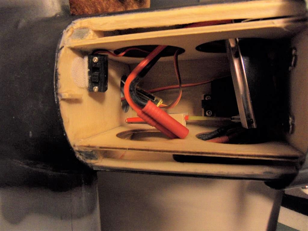
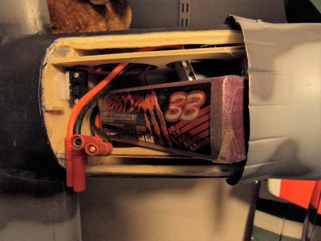
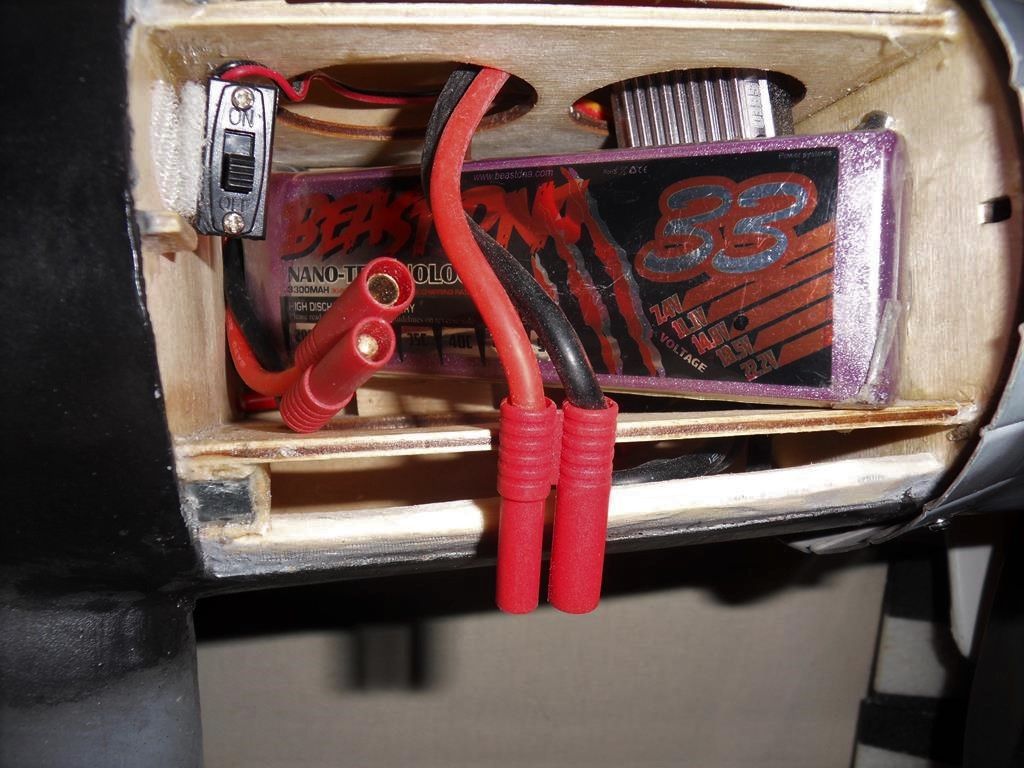
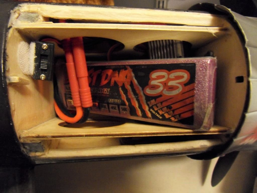
Sorry for the delay in replying. The past couple of weeks have been hectic with builders/ plumbers in the house and now I have some normality until the next batch of upgrading. The pictures should be self explanatory but the following should help.
The flap servos were placed in the forward bottom area of the nacelle to allow the battery to drop as deep as possible into the rear bottom of the battery bay.
Note that the snake allows the battery and cable to pass by albeit with slight interference fit. The ESC is placed across the nacelle front passing the cables between the outer skin and the vertical supports. The ESC rests in the forward lightening holes and is free to move a little.
The battery goes in cable end first doubling backwards to join with the ESC connector above the Lipo.
The top front of the lipo rests forward and lays just under the nacelle cover as I built it. I have fitted 4s cells from 3000 to 3600 without problem. Should the battery lift up, the mechanical advantage of the magnets at the rear hold down any pressure exerted thus far by the Lipo bearing under the front edge of the cover.
I hope this helps
Adrian
-
Tin hat on: Doesn't the wing between the wheels count?
-
Hi Paul,
Your panel lines look good with the highlights, plus the staining is convincing. All in all a very professional finish to the model making it definitely on to be proud of.
-
Yay 46 from 49. Some were process of elimination though. As others have said some were a bit questionable but nonetheless a fun quiz. Need one on modern planes, ww1 and civvies.
-
Hi, I'm putting my tin hat on at this point for as I recall the RAF aircraft of the 50's era had nav lights that were fixed colour and the pilot can select continuous or flashing. In the flashing mode they flashed at about 1Hz (1 per second).
-
I think David has summed up the main issue at the end of his post.
It does seem from what I've experienced (Via my connections with kit manufacturers both balsa and foam types) that the big rise in balsa prices and the sudden hike in kit prices many, many moons ago put the brakes on a great number of model builders hobby and a good number took to their computers for fun as did the kids of the time. Those that enjoyed "Balsa bashing" seemed to suddenly be threatened with the endangered list especially as the search for materials to build cheaper models gave rise to the foamies and models made with a variety of card, foam, XPS etc. It became significantly cheaper to produce a non traditional build model culminating in the rise of the far eastern ARF market where cheap materials, manufacturing and labour made them with few competitors and able to flood the market with (In many cases excellent performing) models that require a minimum of effort to get flying.
Those diehards who have lived through this are still producing traditional builds because so much more can be done with the balsa, ply builds with durability and strength being attributes that foam does not always satisfy especially where competition might be involved. Until the production of composite foam models take a significant hike in costs there will not be cause to change from where we are now, and with so few youngsters taking up this hobby/ sport the future is bleak indeed with the traditional build banner being carried by fewer and fewer.
Maybe what is needed is for the education authorities to put practical craft activities back on to the national curriculum to give the youngsters something to create for themselves so practical skills can be learned and appreciated. Maybe that would plant seeds such that some may grow into modellers.
I may be wide of the mark but this is the way I see things at the moment
Adrian
-
Hi Paul,
Your battery cover looks good. All ideas are gratefully received. How long before the maiden?
-
-
Hows about through 2017 a series of informal fly-Ins hosted by local clubs around the country where 10th anniversary items can be handed out to worthy participants.
Edited By Ady Hayward on 25/12/2016 16:18:55

Glass clothing
in All Things Model Flying
Posted
Sorry wrong post
Edited By Ady Hayward on 31/07/2017 16:11:06