-
Posts
8,533 -
Joined
-
Last visited
-
Days Won
4
Content Type
Profiles
Forums
Blogs
Gallery
Calendar
Downloads
Posts posted by Chris Bott - Moderator
-
-
Ron I guess it would be perfectly feasible to solder rows of pins in place, rather than sockets.
But then that would defeat one of the advantages that I've found, and that is how easy it is to unplug a Rx while leaving all wiring completely intact.
-
Posted by Andy Joyce on 07/05/2020 11:05:55:
Chis looks very interesting what you have designed. Had you got a price in mind for the item yet?
Hi Andy
Apoligies that I hadn't spotted this question before.
I would like to share this with others but am not sure which way to go.
Would you be interested in a kit of parts or maybe just a PCB and programmed telemetry chip?
I guess the 3d printed box is integral too.One problem with this solution is that receiver types come in different pin layouts on the end and case sizes.
This is specifically for X8R and S8R. Is the Rx you intend using exactly the same in terms of case and sockets? -
Stu, I'm not sure I've seen any official documentation but it keeps coming up in threads here and other forums.
Have a good read through this one, for example.
I've had an aileron servo burn out in flight in a warbird and was using the FrSky decoder. This was after 10s of good flights. It landed OK but was making quite a whining noise and was to hot to touch when the hatch was removed. Of course I can't know if it was the frame rate or just a faulty servo.
PS - There's a post of mine in the thread linked, that mentions how to use a multimeter to check frame rate.
-
Yep we'll be along very quickly

As far as I remember there's one more caveat with the FrSky 4 channel decoder - It outputs a servo frame rate that matches the incoming S.Bus frame rate. This is 9mS from FrSky receivers, which makes the servo outputs only suitable for digital servos. Analog ones may work, but may also burn out.
The Bangood ones that I've used all appear to have a frame rate of 18mS which is good for all servos.
They've been very good for me.As Bob says, just don't forget that all servos in the wing will be drawing power through a single servo plug. As long as total current isn't high, they're very useful.
-
Interesting to see you used the FCC version Kevin. Any reason?
-
Thanks, Kevin. Useful links.
-
Tosh, have a look at the help section ***HERE*** Look for "Creating an album and adding photos".
-
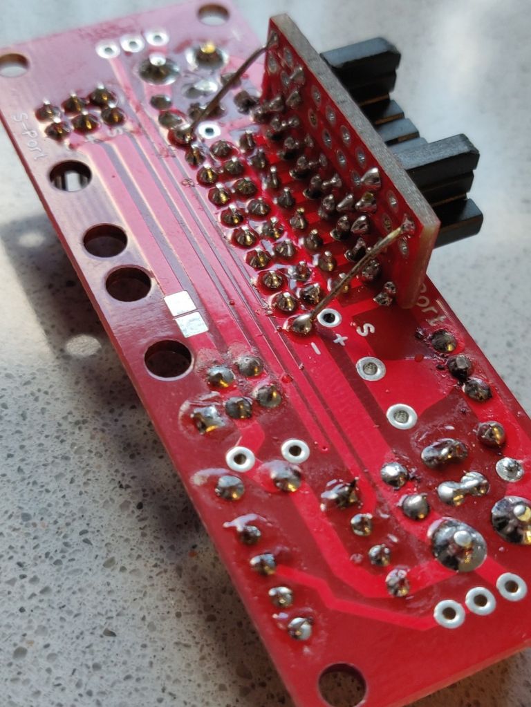
Andy I designed and built these units as something in between using a single supply and using a RB unit.
It accepts two supplies via decent (not servo plug) connectors and combines the two via diodes.
This combined supply feeds directly to the servo pins and also down to power the receiver. The receivers signal pins are routed up to the servo pins.Each incoming supply is seperately telemetered.
I'm at the point where I've had a handful of flights by way of testing them in anger.
In the model I'm using one in, I have a Neuron ESC with it's 7A UBEC supplying one side and a 2S LiFe via a switch to the other side. I've set Neuron UBEC to be slightly higher voltage than the LiFe battery, so that is the master supply and the battery is the backup.
Telemetry is set to shout at me if the UBEC input falls below a set voltage, announcing "Warning - systems on backup power" - just for a bit of a giggle.I haven't thought through how this would work with an RX8R and a "satellite" Rx? But can't see why that would be any different.
I had intended a lot more flying with them by now. After that the plan was to find out if anyone else might be interested in them.
-
I see there's no V2 RF firmware for S6R or S8R available yet. Does anyone know how soon they mean by "Coming soon"?
At the moment, if I upgrade my fleet then I render these useless.
-
I do indeed mean C1. Thank you Peter, it's a good job someone is awake.
-
The final adjustment (I hope). I've just changed my C2 to a1uF tant and I'm getting nice stable current readings even at partial throttle.
The only thing I haven't addressed now, is the fact that all three of the Max/Min readings are now triggered by the Power being greater than previously recorded.
This has the advantage of taking all three at the same moment and I think is actually what we're looking for, rather than recording separate Max amps, Max power and Min volts, as and when they occurr separately.A startup surge is still recorded, I did consider trying to miss that out. But it's real and the meter shows what's going on. If we want to miss it, we have to be gentler with the throttle.
-
That's great news, thanks Peter.
-
-
Mike thanks again for your input.
This morning I've been seeing what I can do just in the software. I led myself up a garden path last night.
We (I) have to remember that due to the simplicity of the design, and that we're trying to keep volts drop right down, we're only using around 90 of the 1024 A/D steps. Only 60 if we Declare 3A max, which I'm inclined to do.
I've come up with this line for amps. Almost the original with an offset added.
Amps = (((Atemp+LOOPS/2)/(LOOPS))*((1.1/1023.0))*45*TrimA)+0.11 ;
This tracks the multimeter much better but leaves a reading of 0.11A whenever no current is flowing.
The reading does ahow 0.15A when multimeter says 0.149 and this is step 1 of the A/D.So I've changed the lines just after setting 2 decimal places to read:
if (Amps <0.12)
{
Amps = 0;
}Peter it would be really useful if you could try this.
-
Peter try this.
I'm sure we can get closer, iteratively but using this line has improved mine.
Amps = ((Atemp+LOOPS/2)/(LOOPS))*((1.1/1023.0)+0.018)*2.75*TrimA ;
Edit - See later post for a newer version
Edited By Chris Bott - Moderator on 01/05/2020 12:42:36
-
Mine is with both tracks used. Calibrated at 2A.
0A at no load.
It does look like we need an offset and a lower multiplier
But If I add a +1 as here
Amps = (((Atemp+LOOPS/2)/(LOOPS))+1)*(1.1/1023.0)*48*TrimA ;Then it reads 50mA with no load.
-
I've just done these tests.
Quite disappointing but I think still suitable for our use. Especially around the 1 - 2.5A area where indoor models operate. Up at the higher end, the PCB tracks felt warm, so maybe we should limit the unit to, say, 3A?
Multimeter 1S Wattmtr
0.20 0.11
0.30 0.19
0.40 0.29
0.50 0.39
0.60 0.49
0.70 0.63
0.80 0.74
0.90 0.83
1.00 0.94
1.10 1.04
1.30 1.29
1.50 1.45
2.00 2.00
2.50 2.60
3.00 3.09
4.00 4.35
5.00 5.66 -
.stl 3d printer files for the case:-
Note: There's nothing in the designs for cable entries. These will vary frm user to user so can be cut or drilled.
Bezel/Front is from the bottom of this page on the Bitsbox website
-
Interesting. I've been doing a bit of calibrating against a more reliable multimeter and I found the same.
I then cut a link so only one track was in use and adjusted the multiplier in the Amps line to 24. So maybe that would be better at 48 or 47 for use with both tracks.
I think that if a user is going to use this for models that all use currents in the region of 1A, then using a single track is better. WIth the knowledge that volts drop will be higher if they move up towards the 5A range.
But those needing full scale most of the time should use both tracks. It's an available choice, anyway.
What's your feeling on having the readng showing 2 decimal places when resolution is only around 50mA?
-
Thatnks Peter. Are those adjustable through the PCB, as well as from the top?
-
Hi Paul
That's interesting, how do they tell you that the LCD is out of stock? It appears to be available here
The .stl for the bezel is on that same Bitsbox page. That's what I'm using.
I'll post the other two parts later. I'm screwing all 3 together with M2.5 x 20mm screws. These work fine but can eventually strip the holes if they're screwed in and out many times.
I'm also using Header sockets to mate with the pins in the display. Those were from my spares, I'll have to find a sourse for them.
As for trimpots, Peter may be better paced to advise as it looks like he has some that fit that PCB.
I'm fairly sure these from RS will fit.I guess a full parts list is in order now, I'll have a look at doing that.
The new PCB (just ordered) should take two sizes of trimpot and I've made provision for a couple of header sockets at the far end that connect to nothing. These will mate with a couple of pins inserted in the other end of the display and should keep the PCB physically secure.
-
Looking good Peter.
It will be good to hear your opinion on the sensor tracks.
The multiplier in the sketch is for using both tracks in parallel.Using both in parallel is good to keep the volts drop down, but there's a downside (because this was designed to be particularly simple).
The lower the volts drop, the lower the volts across the whole sensing range so we're only using a fraction of the 1.1V of the A/D converter range. Using a single track will give you twice as many A/D steps, i.e.greater resolution.
-
I've now ordered some new improved PCBs.
Hopefully they have all the niggles from the first batch fixed, along with a couple of improvenemts including something to physically stabilise the "loose" end of the PCB.
-
That's good Dennis.
I've put the much improved sketch here OLEDPwrMtr V0.3.ino
Clearly not the best way to share files. But it's all I have.
This one has the improved averaging, is much tidier and is saving Max/Mins whenever power is at a new max.
I'll still be trying other methods.Edited By Chris Bott - Moderator on 24/05/2020 13:09:29


1S Wattmeter
in Gadgets and Electronics
Posted
Hi Peter. I think, just from your results, that this is asking too much from our very simplistic design. Are you able to test with a multimeter for comparison?
These came today
Of course I'm out of Arduinos so ordered some to arrive last week. A parcel finally came yesterday but it contained an HDMI cable, so I'm now going through a returns procedure. I'll get the money back 14 days after they receive the cable back. (Why is nothing straightforward?)
So more have been ordered and I'm at the mercy of the mail service, again.
I'm just contemplating whether to retrieve a used one from a previous project. Can I guarantee it will still be a working one by the time I have it unsoldered? I'll ponder a little longer and let you know if/when I have any progress.