


Craig Spence
-
Posts
1,911 -
Joined
-
Last visited
-
Days Won
1
Content Type
Profiles
Forums
Blogs
Gallery
Calendar
Downloads
Posts posted by Craig Spence
-
-
It’s official, this is the last bit of the fuselage I can sheet until the retract turns up ?
However, I’m really enjoying this. Some of the curves are a nightmare to get right but I’m sure that these curves will look great once done and sanded in.
The back end of the wing was very tough.I’ve got a few more small jobs on this before I have to pull my finger out and change the workshop around so I can start on the stab at some point.

-
 5
5
-
-
1 hour ago, Nick Somerville said:
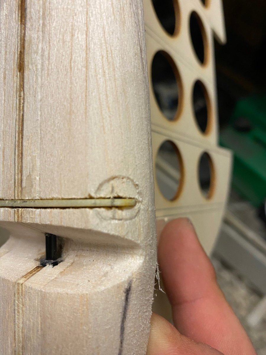
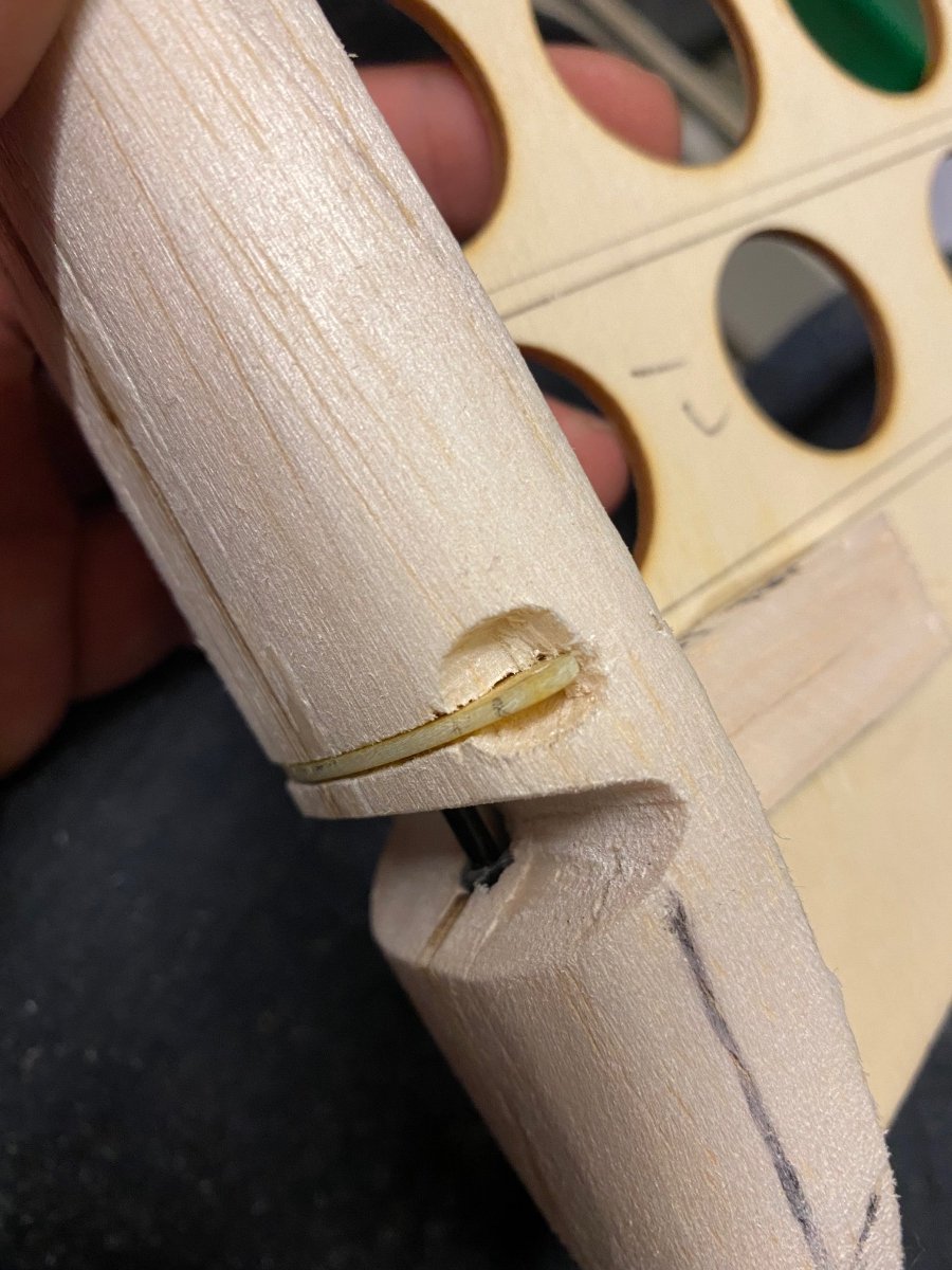
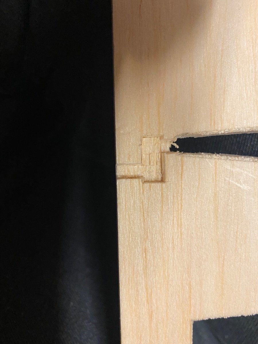
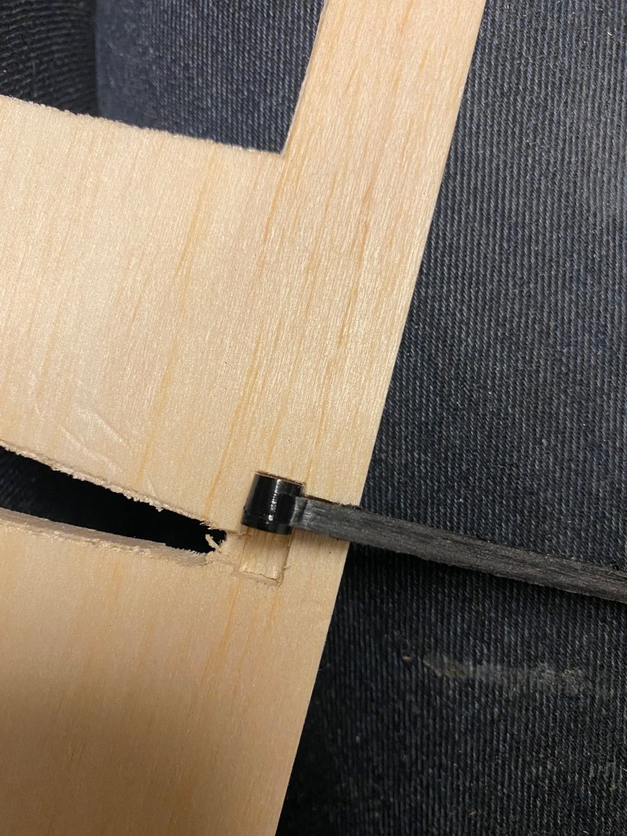
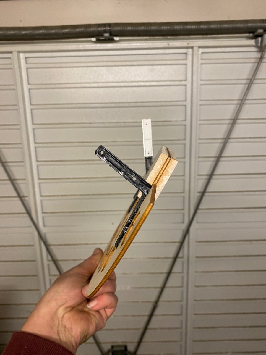
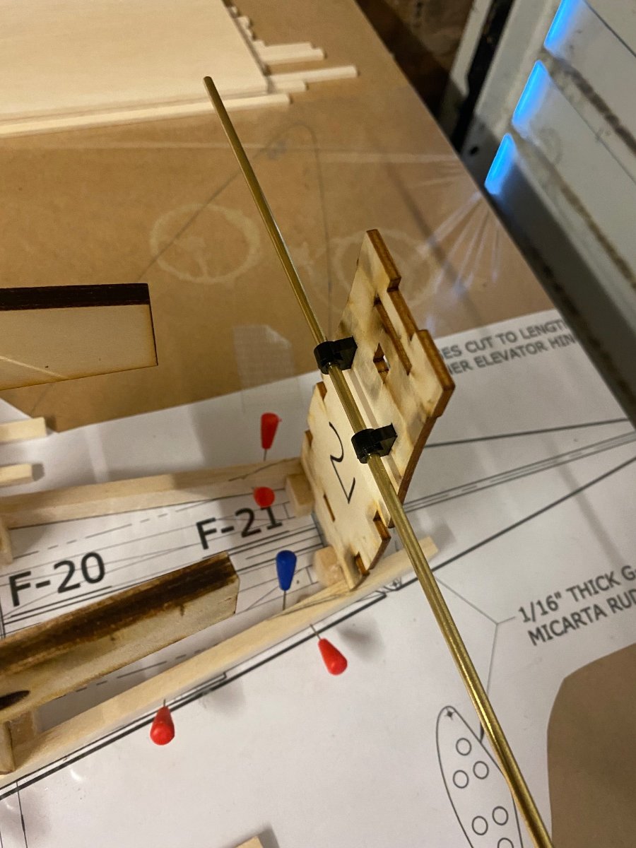
Substantial build and great to follow along Craig. Can you elaborate on materials used for the rudder hinges please. From what I can see you have cut the hinges from carbon plate of some sort and then used a removable carbon rod to run through as a pivot. If the rudder is intended to be removed for transport how is the pivot rod held in place.
Hi Nick and thanks ?
The rudder hinges are a type of plastic which a bought from America
CB associates I believe and were detailed on the plan.
The pin is 3mm carbon rod and will be fixed in place at the bottom with epoxy.
It’s only removed if I need to repair it so would be a case of just drilling out the lower hinge 5mm or so.
I still haven’t decided covering material yet but the top of the rudder and bottom will be carved from foam to keep the weight down.
The balsa post is quite heavy and it’s a ply former. I will seal the foam with epoxy to make it tougher.
-
1
-
-
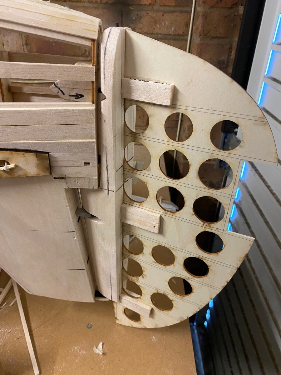
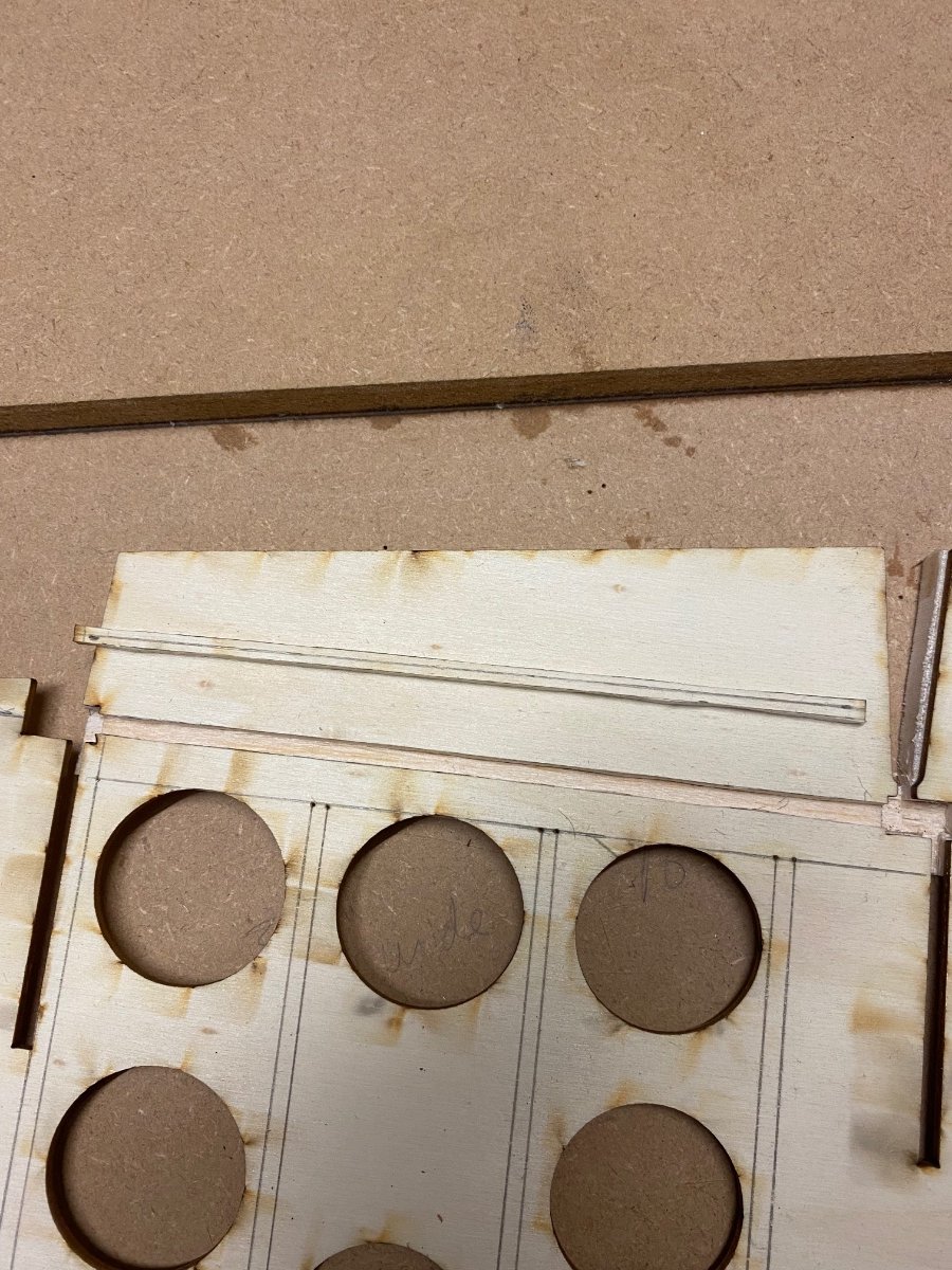
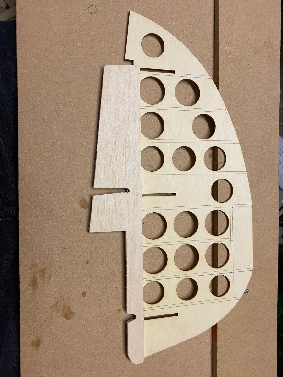
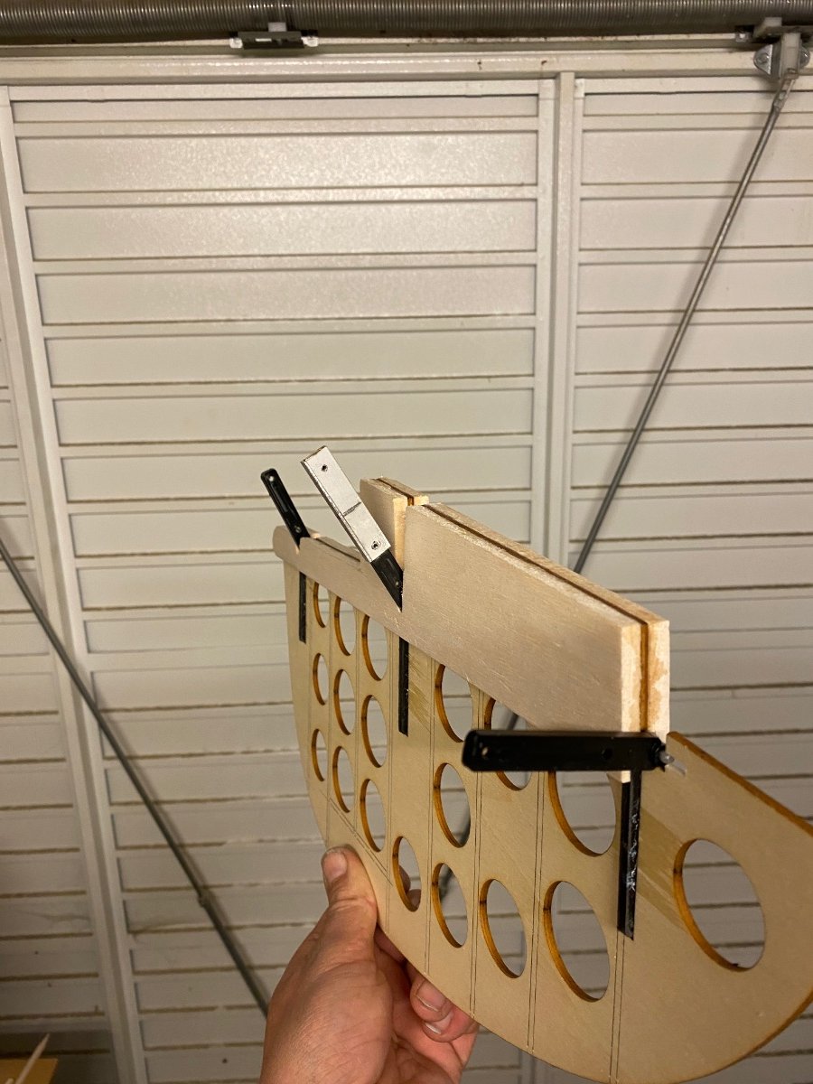
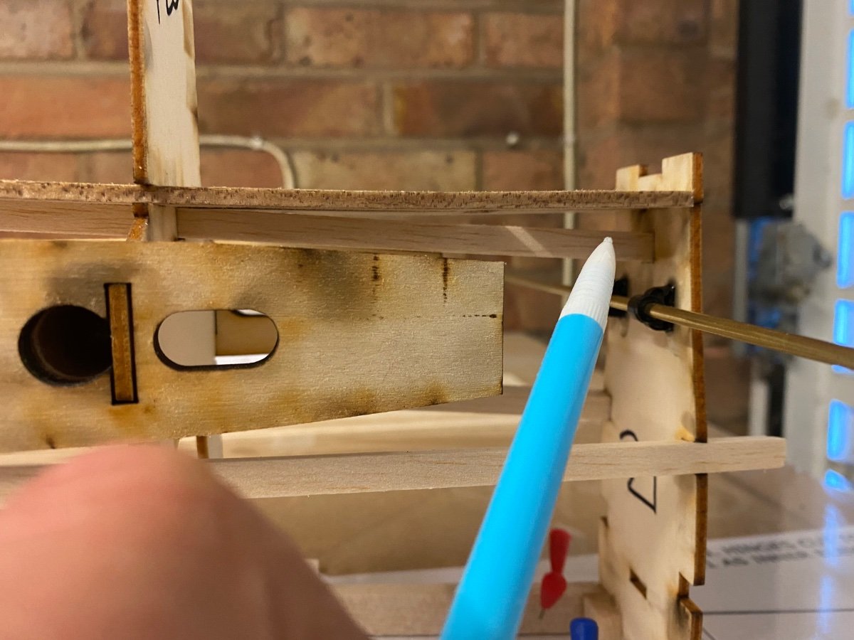
Only a little bit of work tonight, dry fitted the ruder closed loop arm and cut out slots for the clevises.
Dry fitted to fuz again and sanded more. Cut and added ribs to stop warping.
This will now be put to one side for a while as I have another area I can sheet whilst waiting for the retract.
-
2
-
-
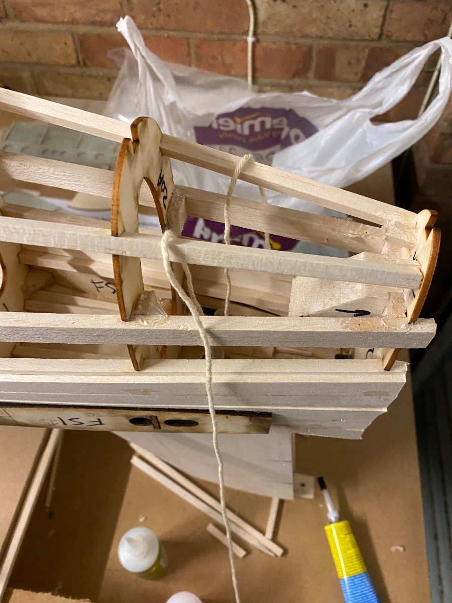
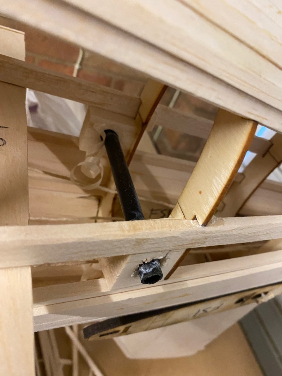
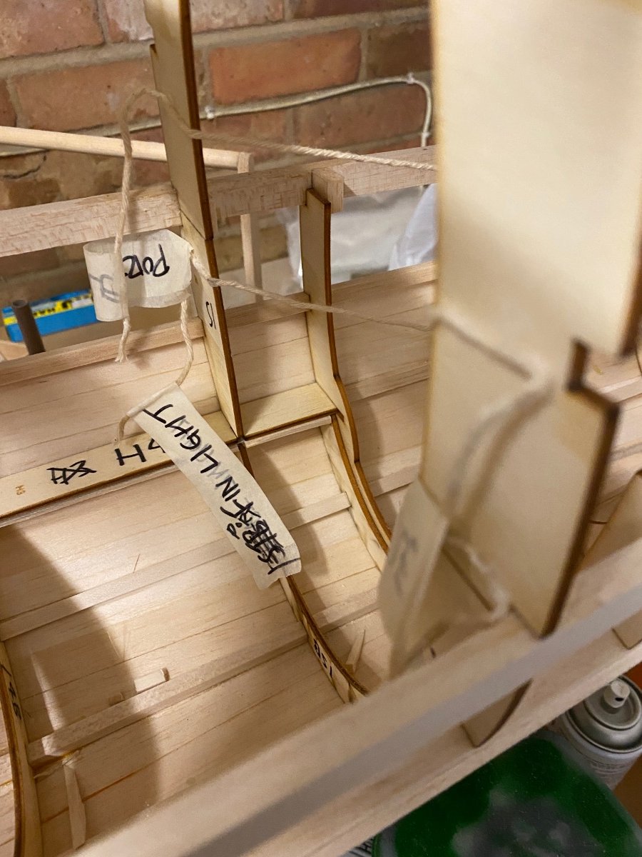
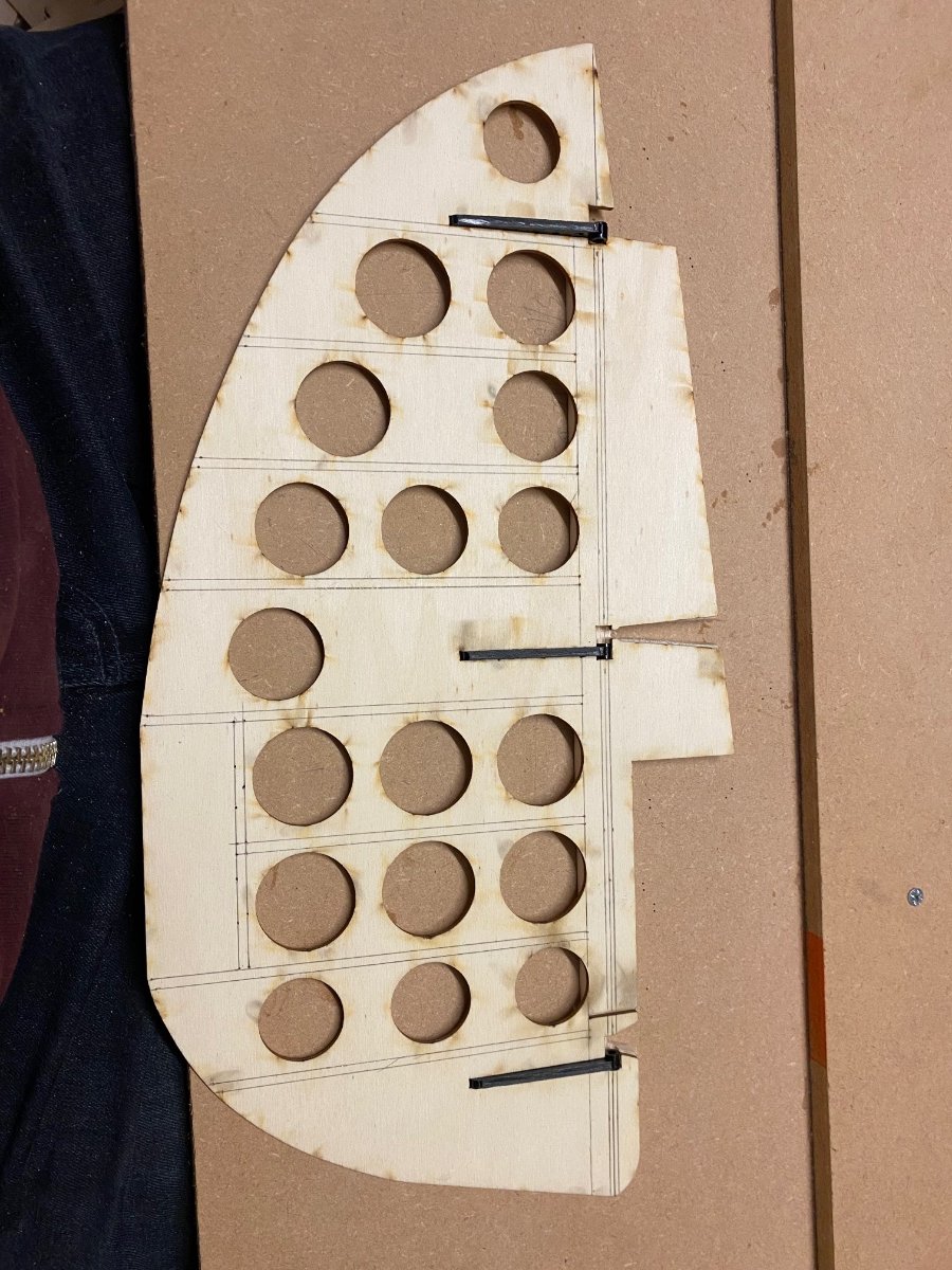
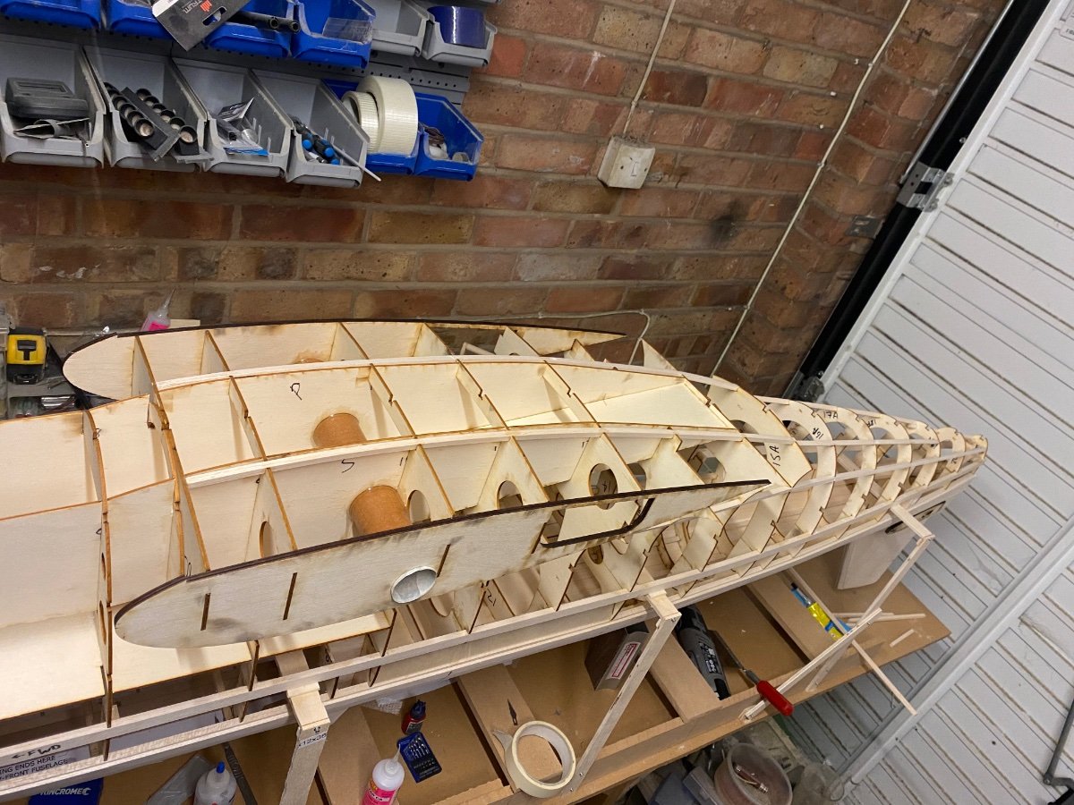
Yesterday and today I’ve been working on the rudder and it’s surprisingly a lot of work! (Far from done).
It’s got a lot of movement which is what I’ve strived for.
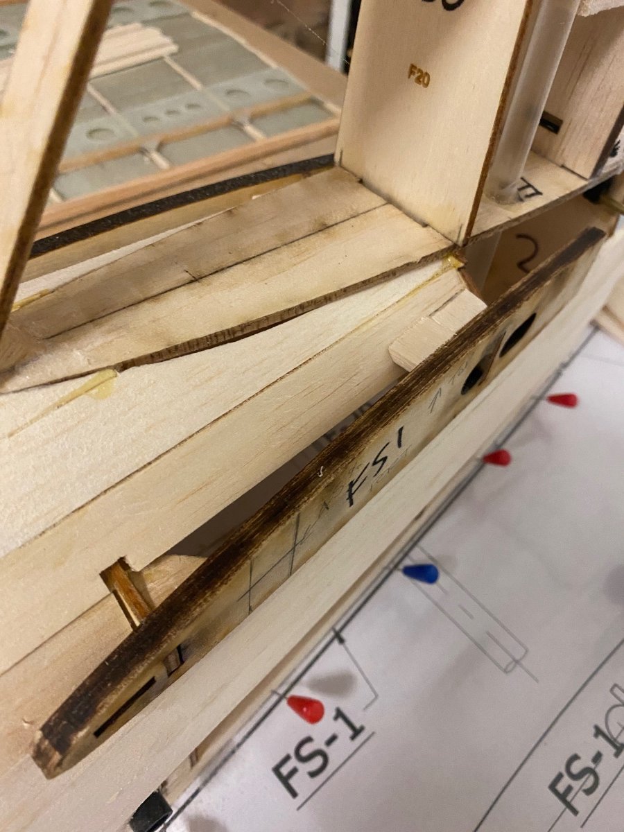
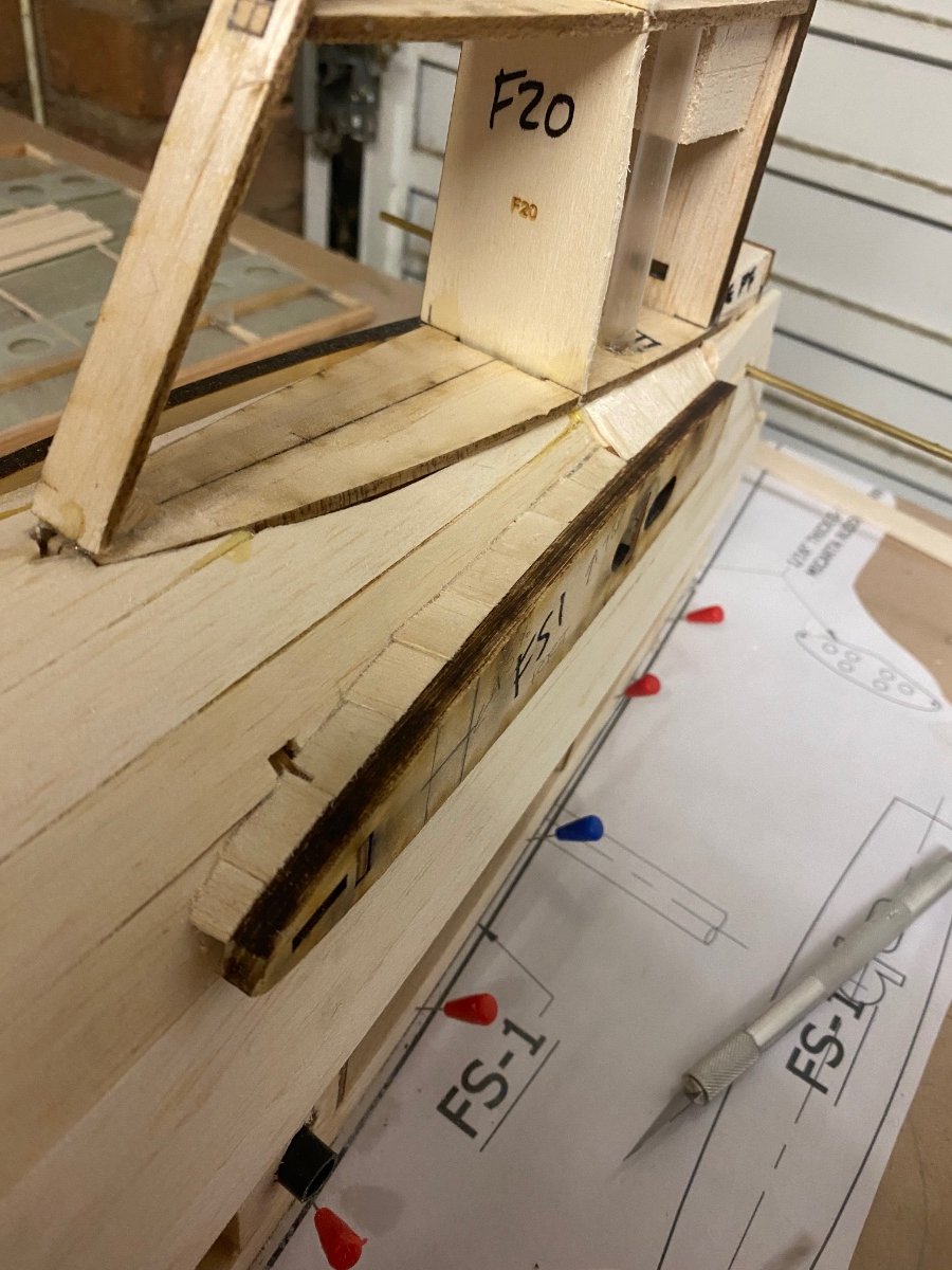
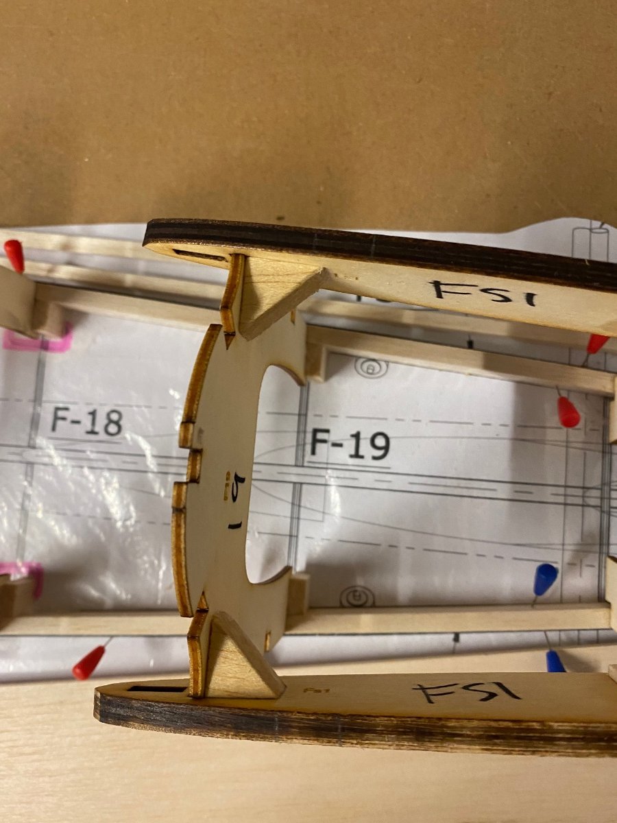
I’ve also sheeted part of the tail. Due to the build up of the wing center section I’m able to sheet some areas whilst waiting for parts. This area in particular will be a challenging bit for fairings and openings in the front of the wing.
I’ve also pulled some string through for servos and lights.
Ive also added a scale Jack point which will be used for a transport/ assembly frame later.
Exhaust dry fitted for a visual.
-
1
-
-
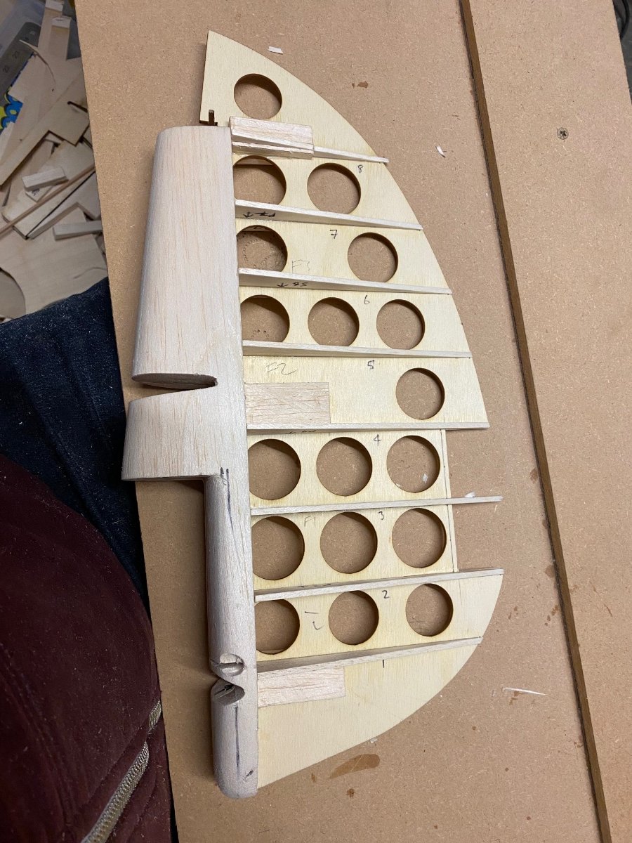
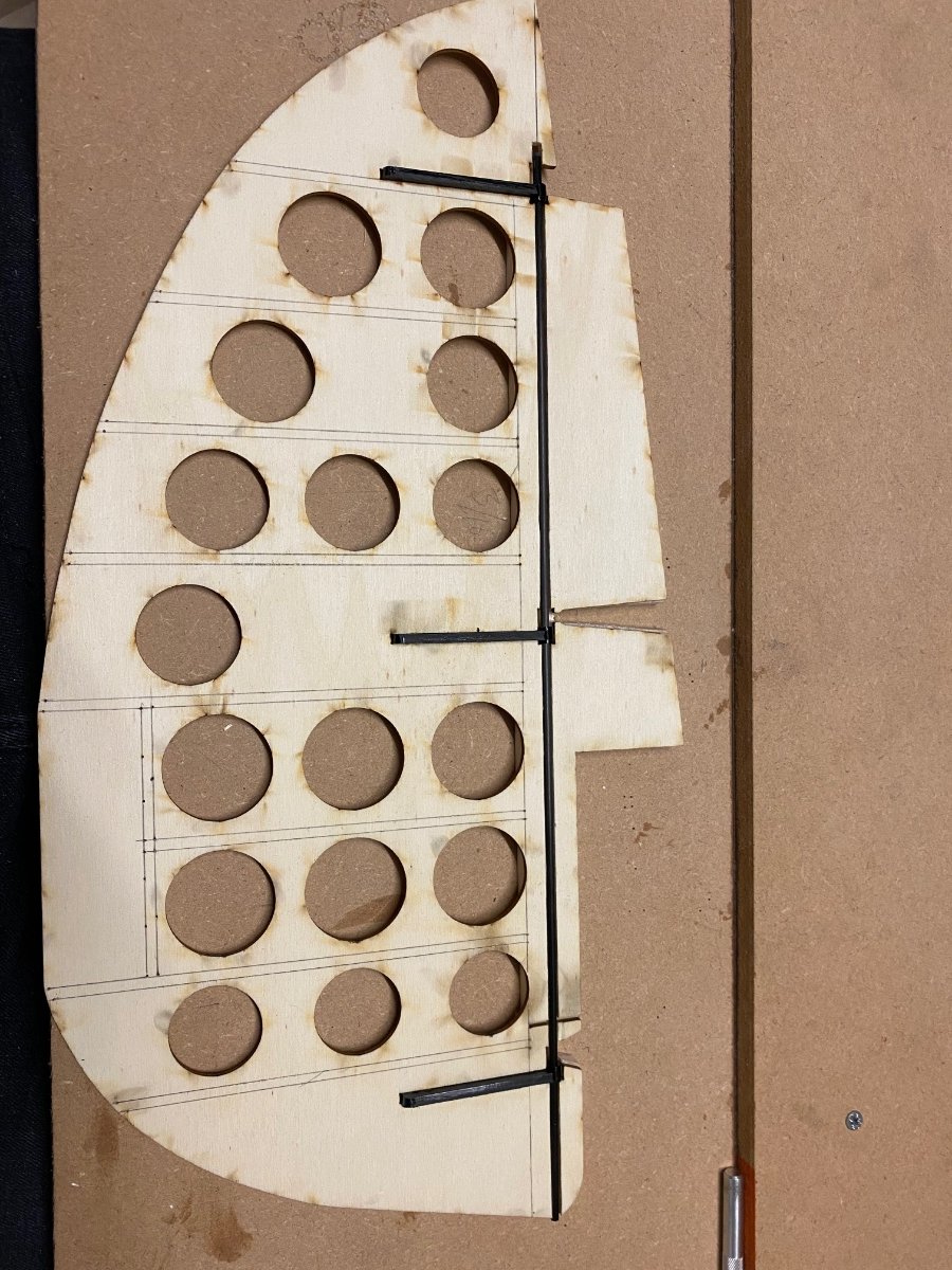
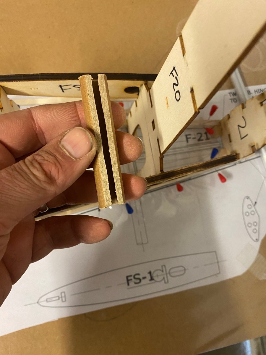
Running out of options I decided to crack on with the rudder.
Good job as well because I needed to do quite a bit to get the deflection I want.I think this may be a bit of a pig to do and I’ll find out over the weekend.
What’s quite strange tonight is that I took a sheet of 1/4” and 1/2” in the garage straight and when I left they were both warped! Along with the rudder!
The recent cold snap must have a lot of moisture in the air.
Also slightly worrying ? as I have a long time to wait for parts but I’m sure I can sort any issues that arise.
-
2
-
-
Due to work commitments I haven’t been able to get on this lately.
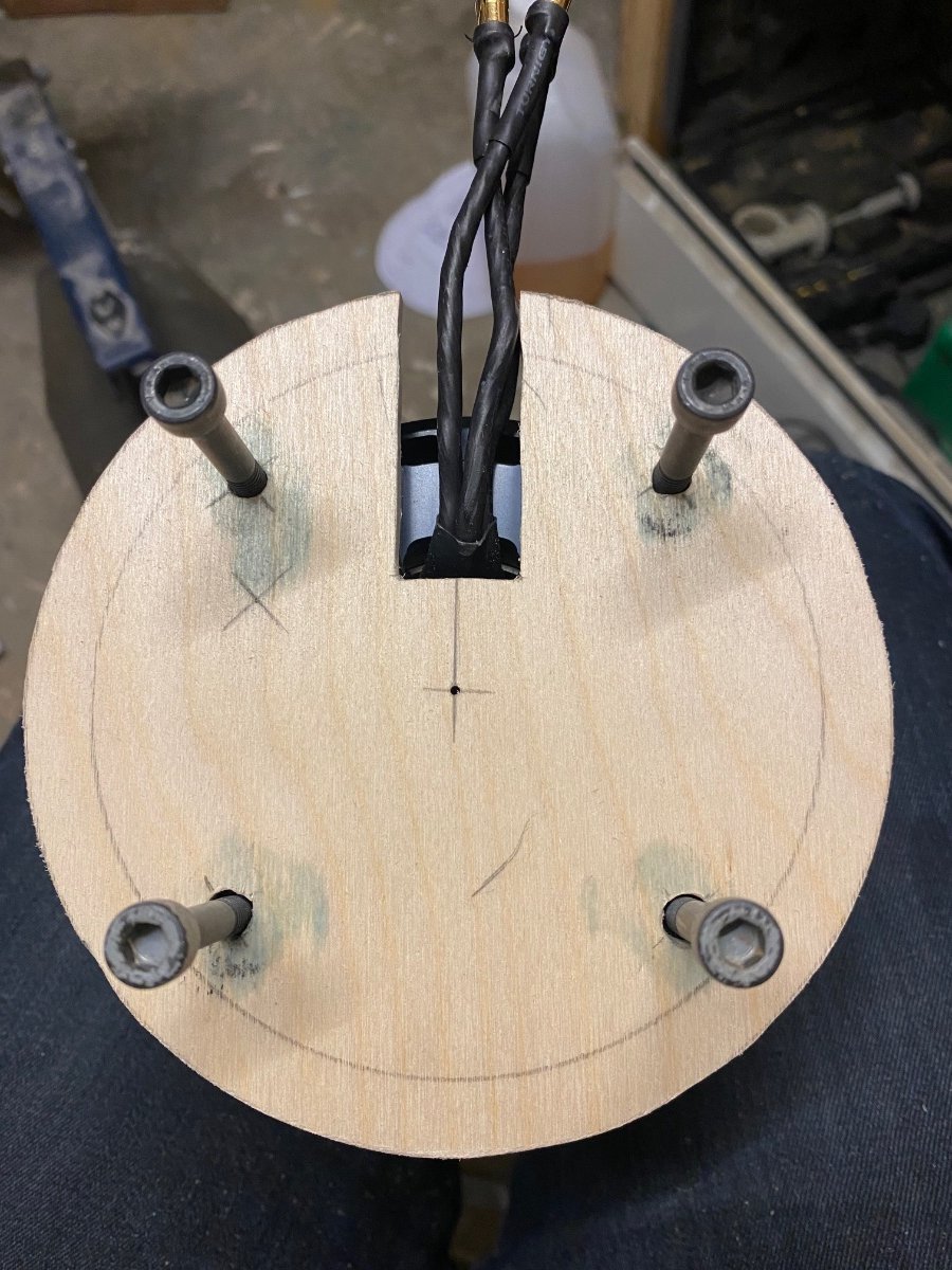
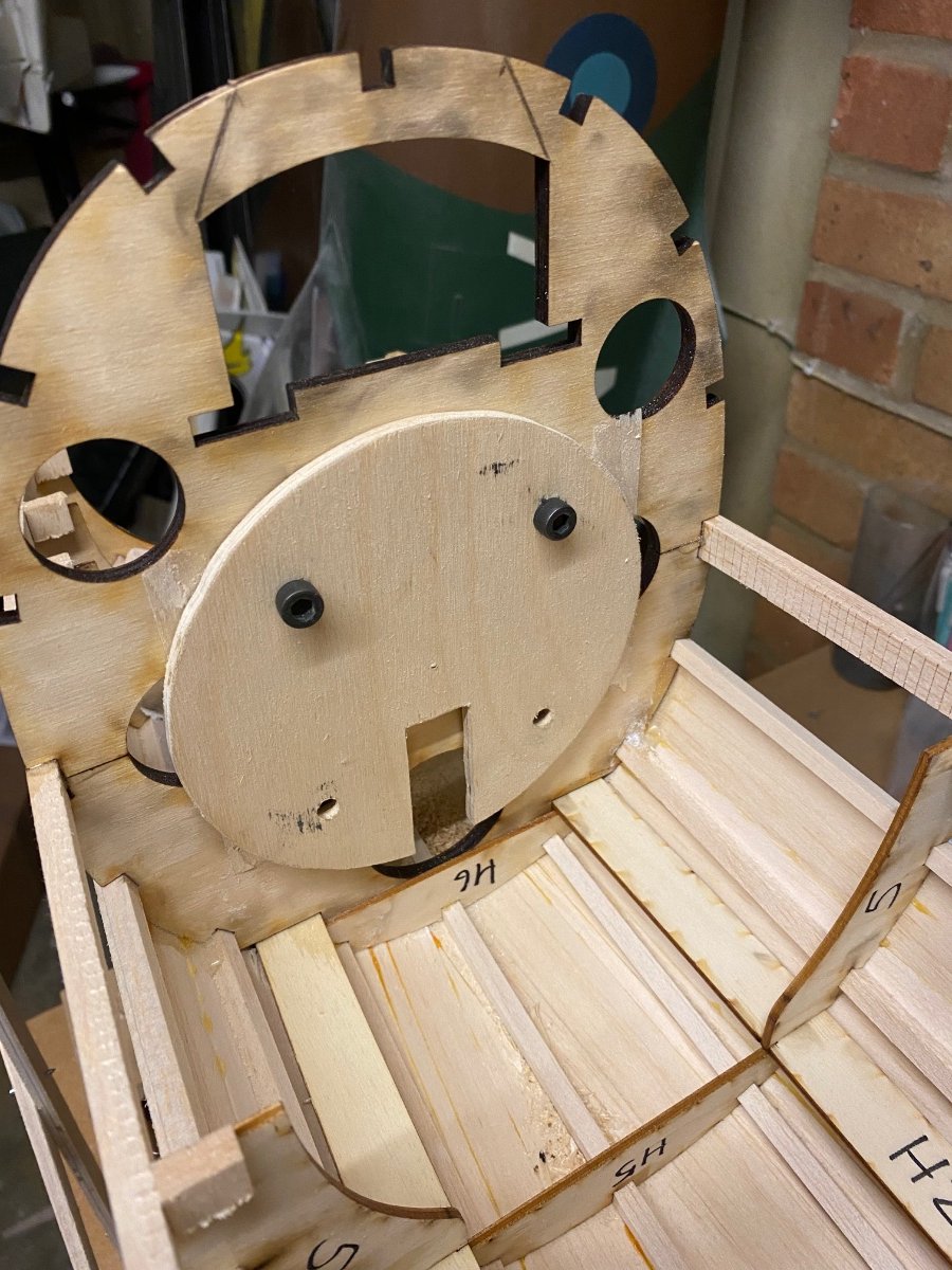
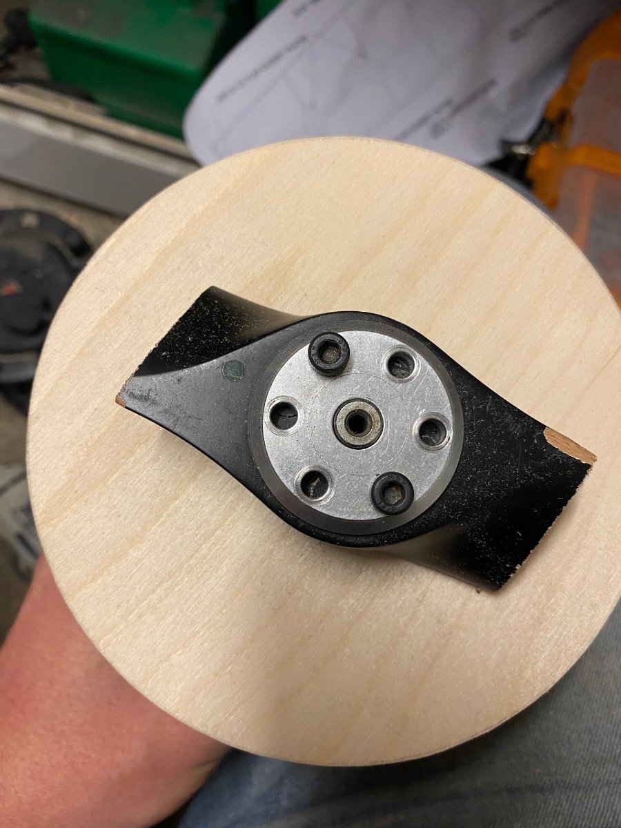
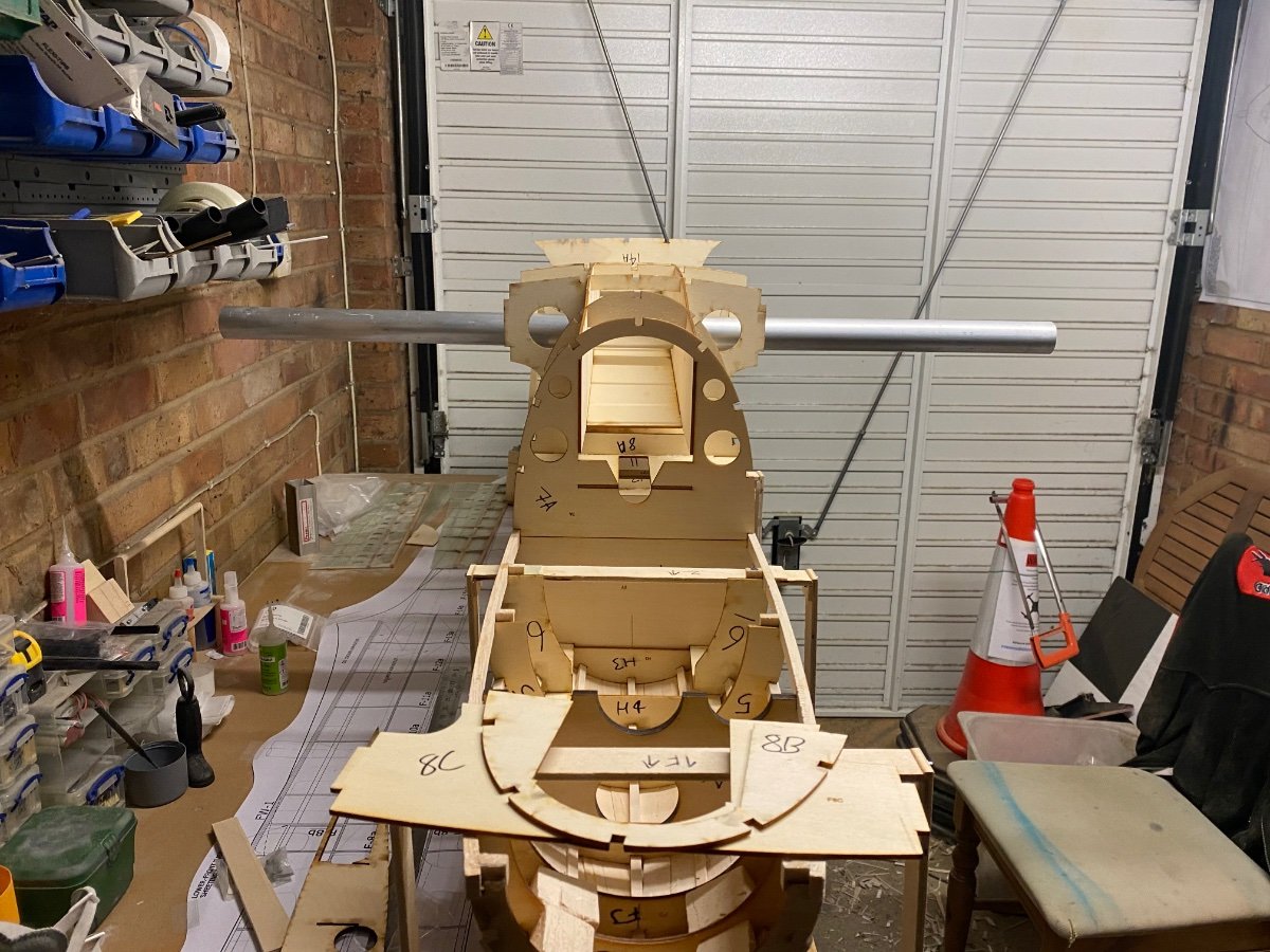
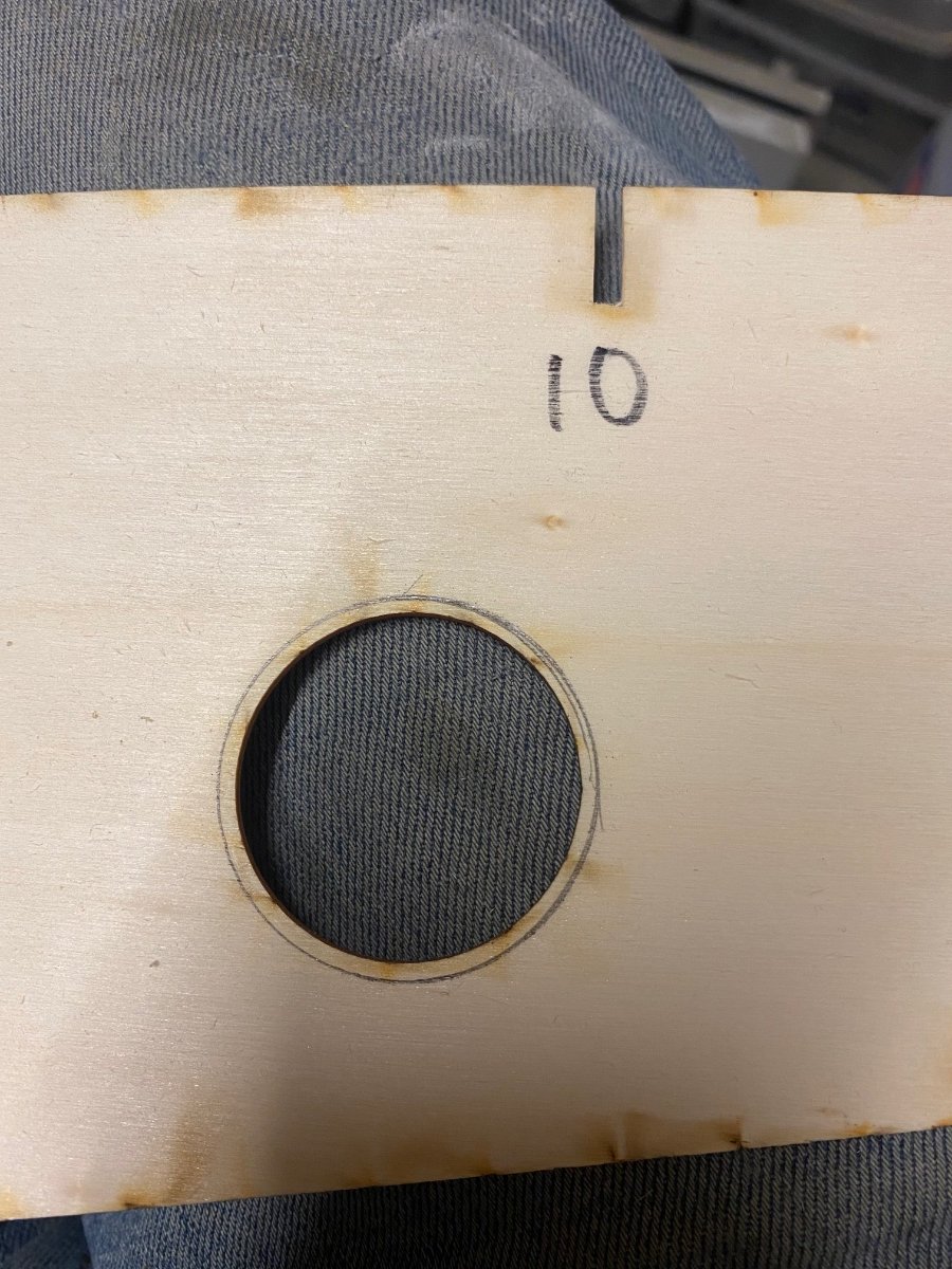
Tonight I’ve cut a ply backing plate for the motor, the aim of this is to aid alignment when mounting after I’ve finished the nose and sanded it.
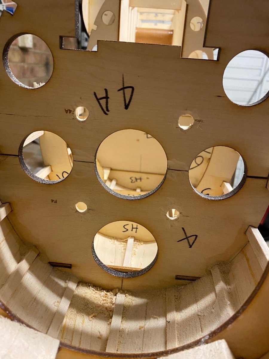
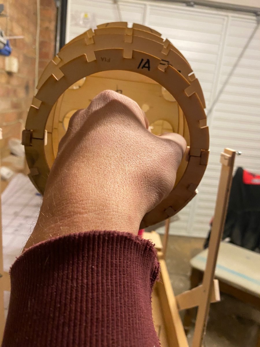
The fire wall holes have been drilled out to 10mm allowing for adjustment when installing. The backing plate will have epoxy smeared on it and when aligned will set in place giving a solid mounting and accurate.As you can see there is no room in the nose, I can barely get my fist in there meaning I have to allow for plenty of movement. Hence the reason I’m going with the stand off set up I’ve chosen (pictures of that will be up soon).
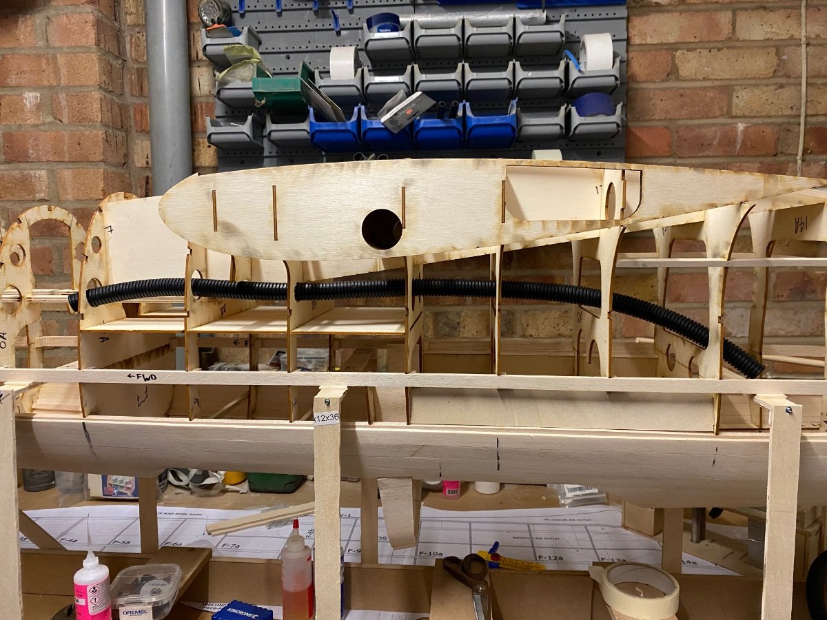
I’ve also went ahead and glued the nose retract rails in place. The retracts won’t be coming until end of April/ start of May so I won’t be able to sheet it until I’ve installed the retract.
I also have to work out where I’ll be installing the servos for the doors and how I can do it so I can remove if needed for maintenance.
Lastly I installed a pull through tube for servo wires. Not something I normally bother with but this plane really is tight for access in all areas.
I’ll have to have it all strung up with pull throughs for the entire build which is going to be difficult due to the finishes it requires.
Anyway, onwards and upwards, hope fully I get the items sooner rather than later so I’m not delayed too much.
-
3
-
-
2 hours ago, Dwain Dibley. said:
just read thru from the start, terrific stuff, looking forward to the next instalment.
D.D.
Thanks very much D.D., hopefully I will be back on the board this week.
-
14 hours ago, Martian said:
its coming along beautifully
Thanks very Martian, it doesn’t look it but it’s a pain ?
I’m enjoying it and looking forward to the wing once I have the retracts.
-
1 hour ago, Graham Davies 3 said:
I think they're a standard size stand off Nick. Try Essentra or TR Fasteners, they have most things
Graham
There a standard size but not what I need, sleeved stand offs are no good for the application.
Once I get sorted I’ll post pics and you’ll get what I’m on about.
I was going to do a frame but it would be inaccessible, it’s a very tight nose area and that’s why I never went IC.
-
12 minutes ago, Nick Cripps said:
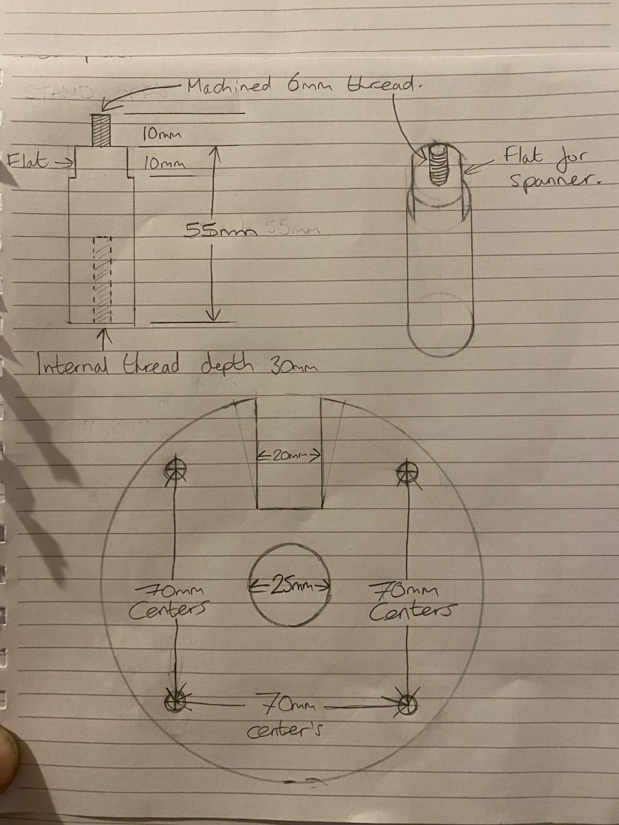
Fair enough. A decent quality studlock compound is unlikely to work loose though, so you could then drill through and tap both ends for 10mm or so which would be sufficient. You could also dispense with the flats and drill through the diameter to take a tommy bar which would be much easier to produce.
By the way, I'm impressed with the build and rate of progress so far, should look great in the air.
Thanks very much, really appreciate it.
Hopefully I’ll get the bits I need soon & I can start cracking on again.
I considered drilling a hole for a Tommy bar as well but wouldn’t have the room, it’s really tight.
Your right about the flats, they’ll be no requirement for them when the design changes again.
-
17 minutes ago, Nick Cripps said:
The standoffs look to be more work than necessary. Why not cut some lengths of ally bar, drill a clearance hole through and then use 6mm studding?
Thanks Nick, I’ve had similar feedback from a friend regarding this.
So, the holes of the motor back plate are threaded but can’t take a nut.
Plan is to tighten the stand-off to the back plate of the motor. If I use stud alone in a threaded sleeve with thread lock there is a possibility it could work loose.
I have been considering drilling a hole through an ally sleeve & taping it.
Then install the 6mm thread, drill through sleeve and thread a pin it.
Then install bolts through fire wall to threaded stand off sleeve.
it’s all about ease of removal/ installation in future, the hole at the front is tiny & through the hatch at the front it’s tight.
Always happy for feedback & ideas though ?
-
Slowing down now but still have jobs to do.
Cut nose retract rails from 1/4” ply and dry fitted them, a little fettling of the formers but otherwise all good.Quite happy with the set up as well, it gives good support to the firewall which is otherwise seriously lacking.
Also done a sketch for the standoffs I need and hopefully these shouldn’t be too much bother for my friend to machine.
-
Limited on what I can do tonight as I’m waiting on retracts and I also need to get standoffs sorted (standoffs are being done by a friend in future).
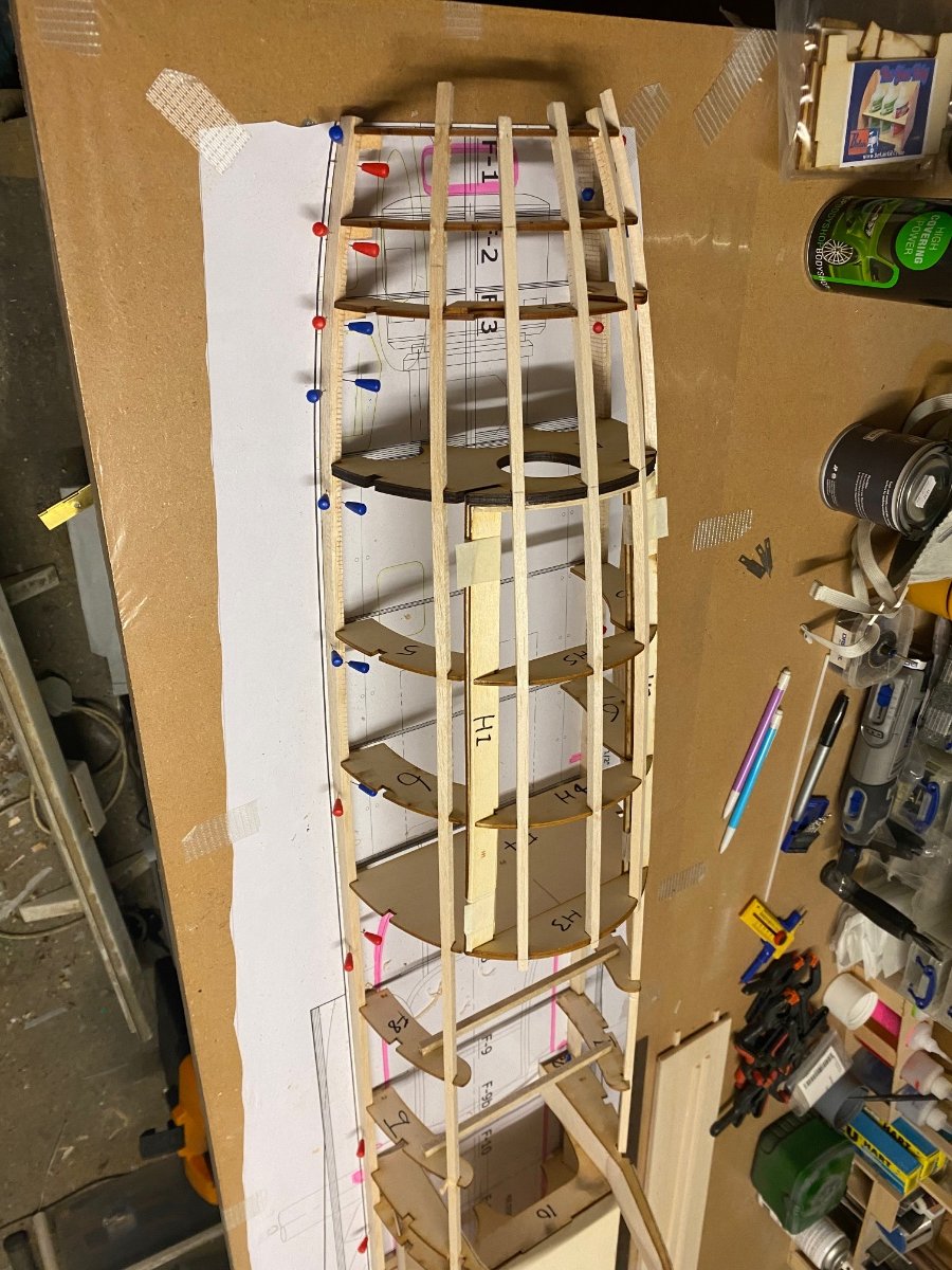
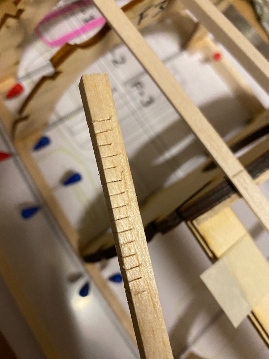
I’ve added the stringers that I can and some of them take a real tight curve and also a twist.
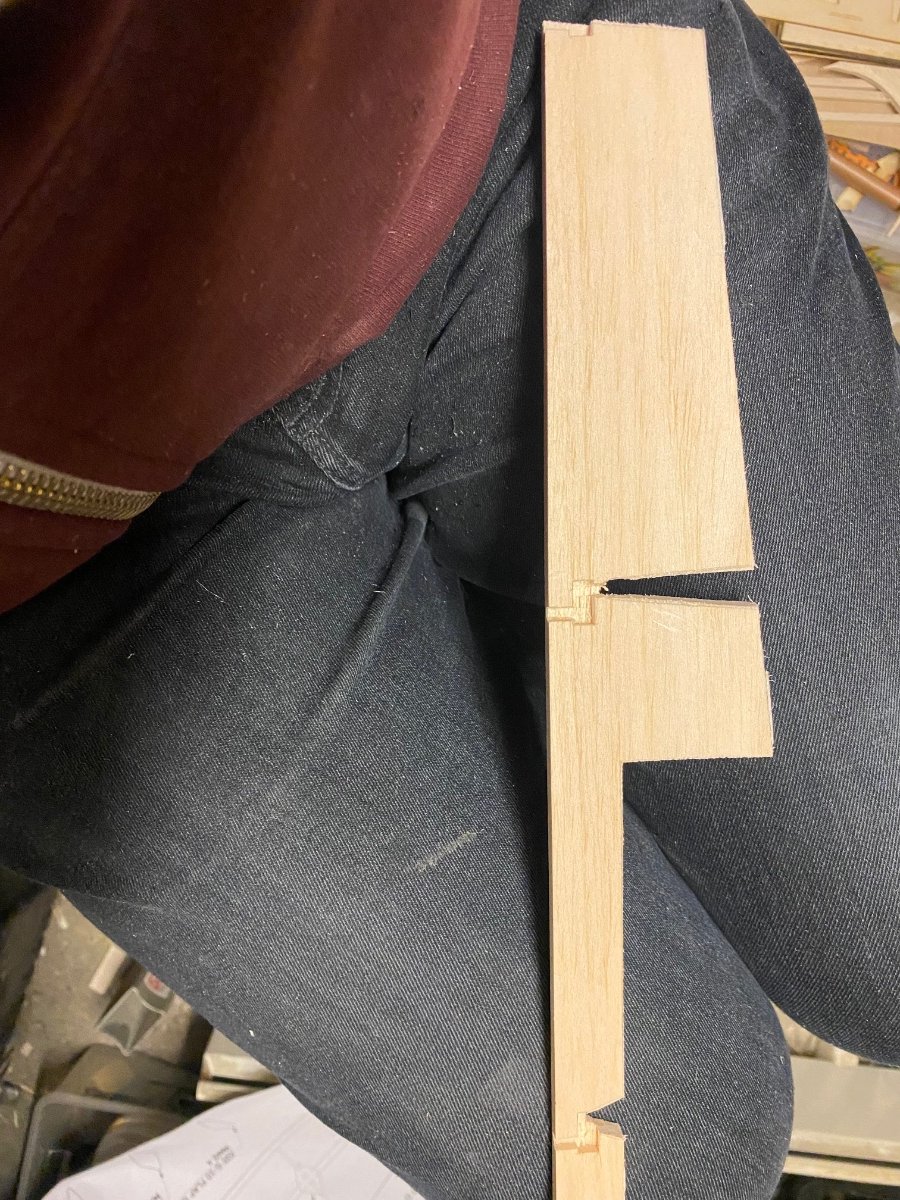
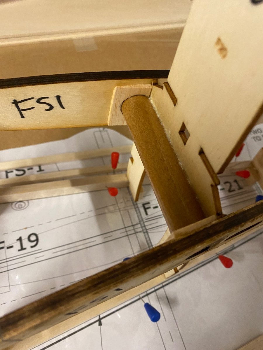
Glued the firewall down in place with epoxy and also the wing tubes.I’ve also set out for the rudder but quickly come to the realisation that I can’t complete the rudder until I have the rear section of the fin complete because I need that for the profile (have to cut my own ribs for the fin).
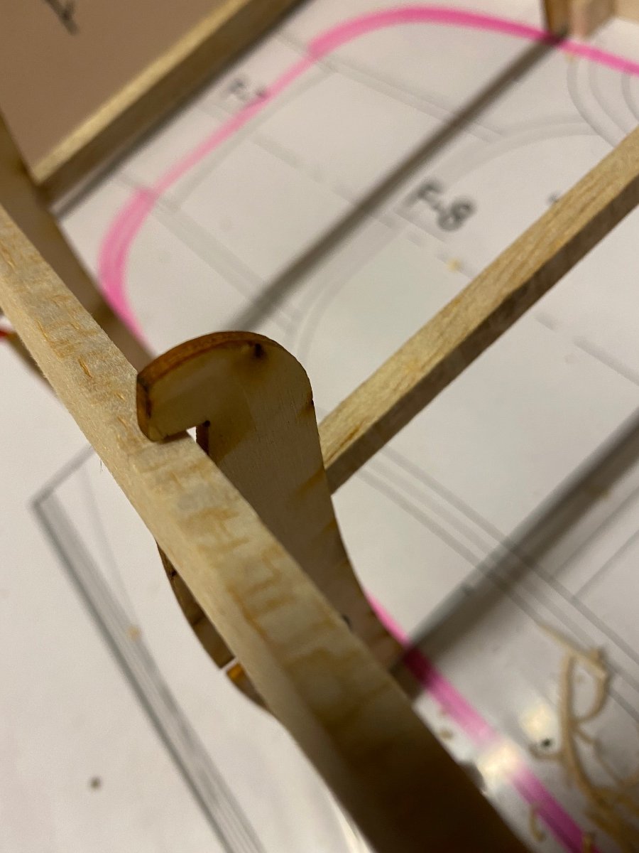
I will be able to do the rudder post and hinges so may do that tomorrow?I may be able to start the stab so that’s probably going to be my next job.
Cheers
-
2
-
-
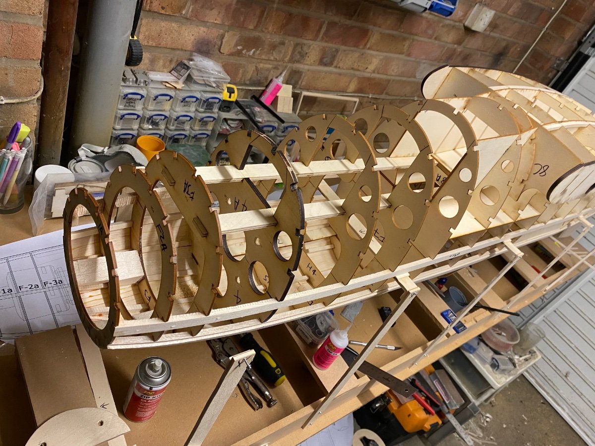
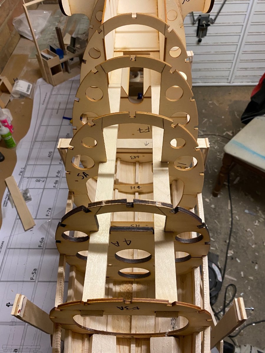
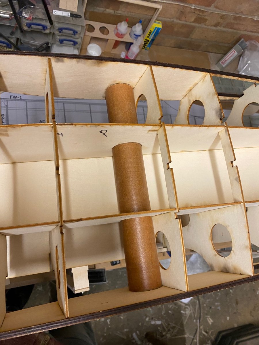
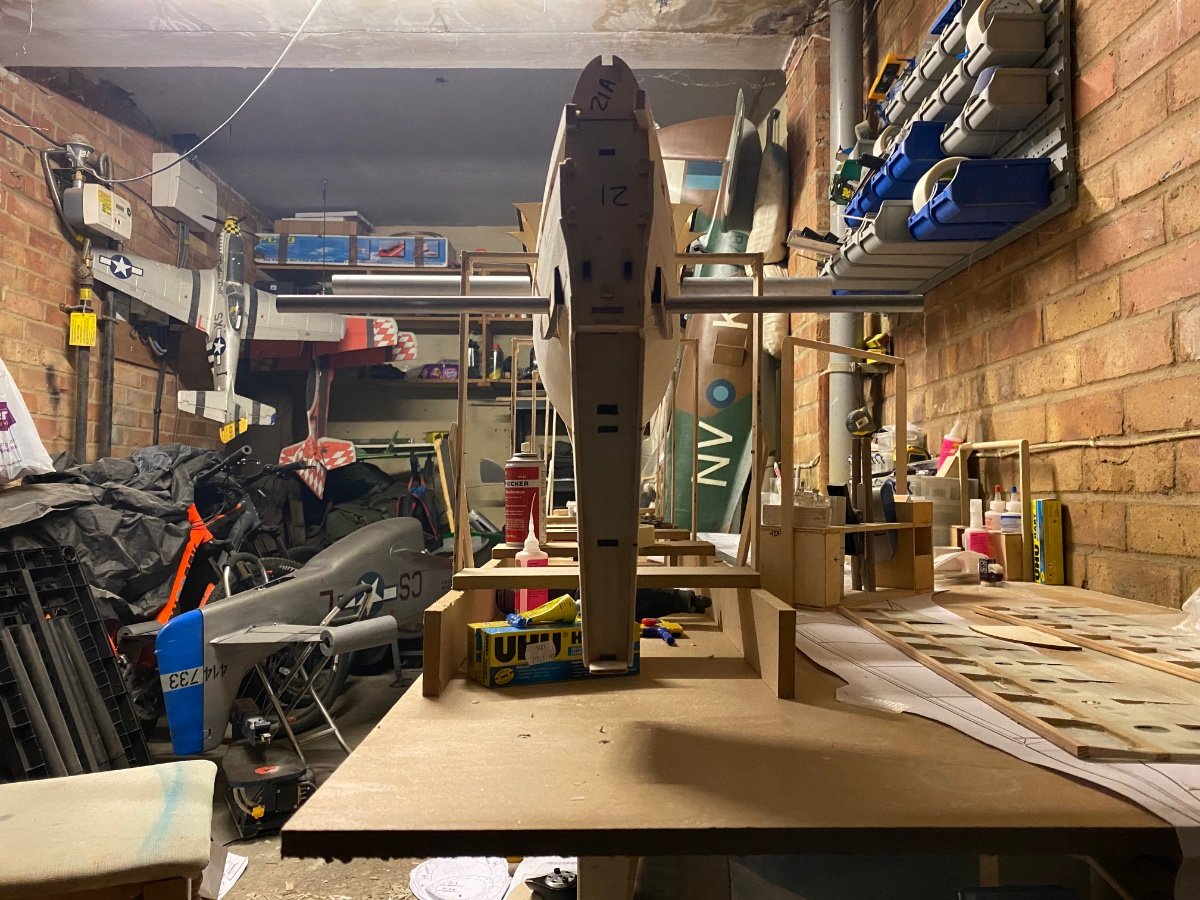
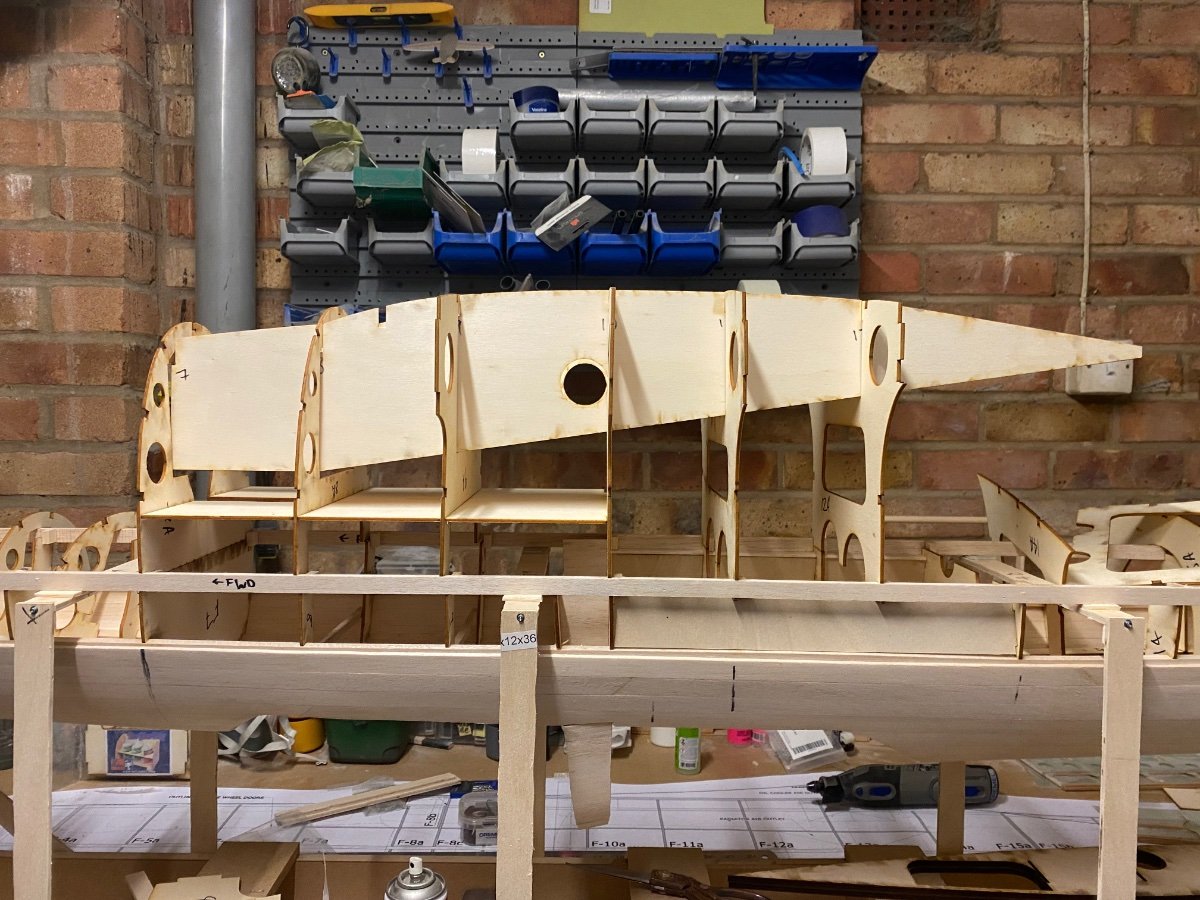
Slow progress tonight with a lot of pausing for considering options and planning.
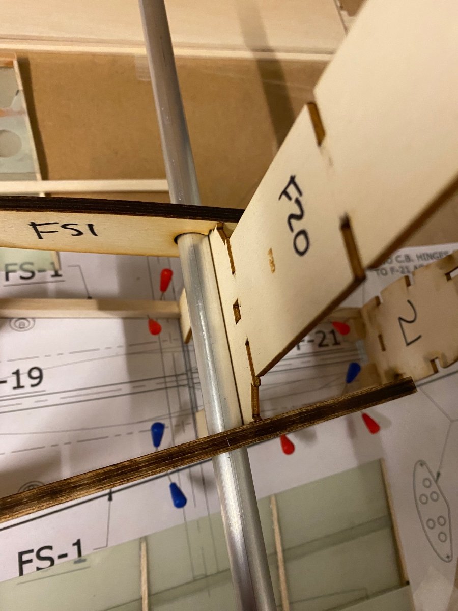
All Aft formers glued in place, main wing tube sanded flat and glued in place along with ribs.Checked alignment between main wing tube and tail tube and thankfully it’s bang on.
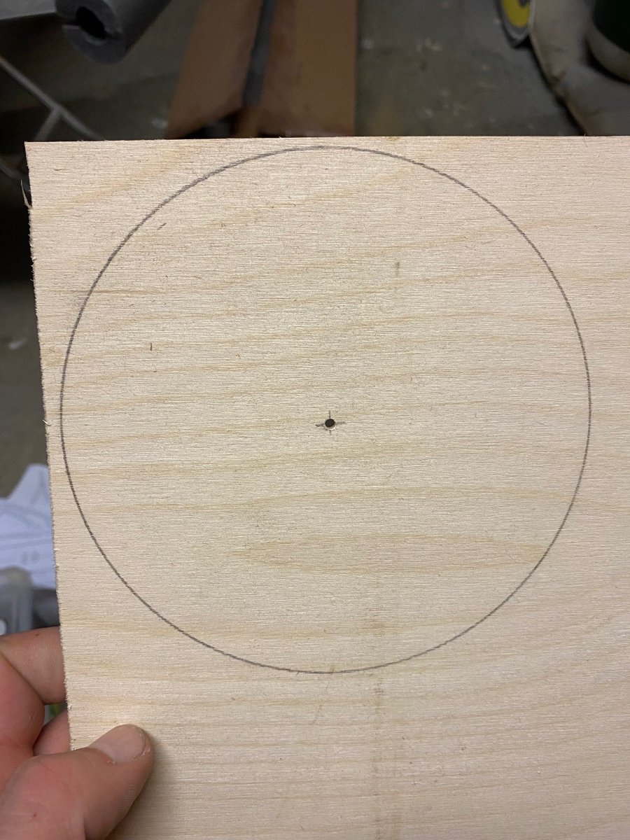
Cut a 6” ply spinner backplate for the motor and offered it up, I need to make up standoffs and a backplate for strengthening the firewall.
Nose retract is not due to be complete until the end of April (plus delivery time) so I’ll have to plan to clear the bench at some point to build other parts.
I may try and fit the retract after so I can keep cracking on.Time will tell.
-
3
-
-
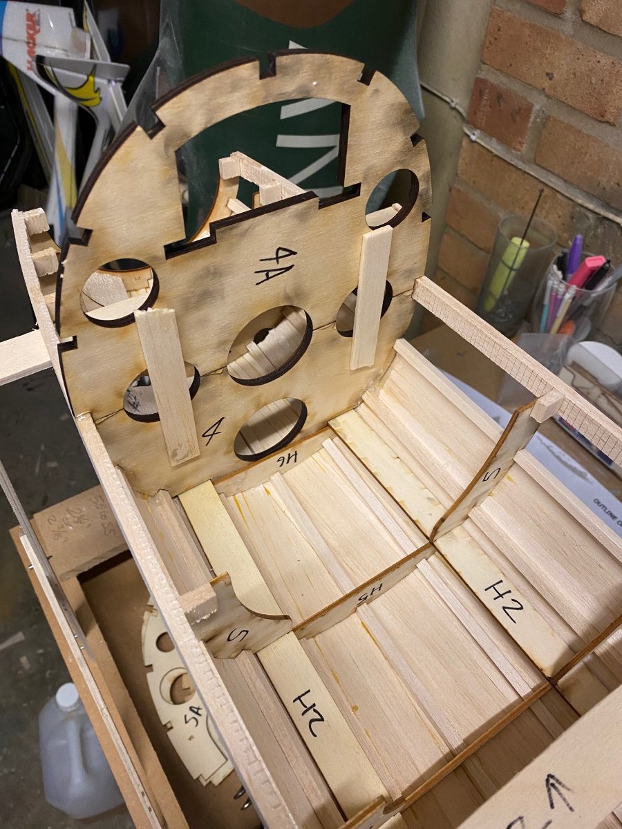
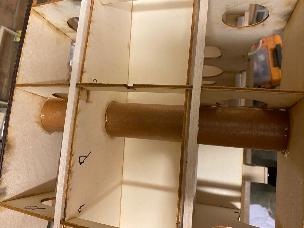
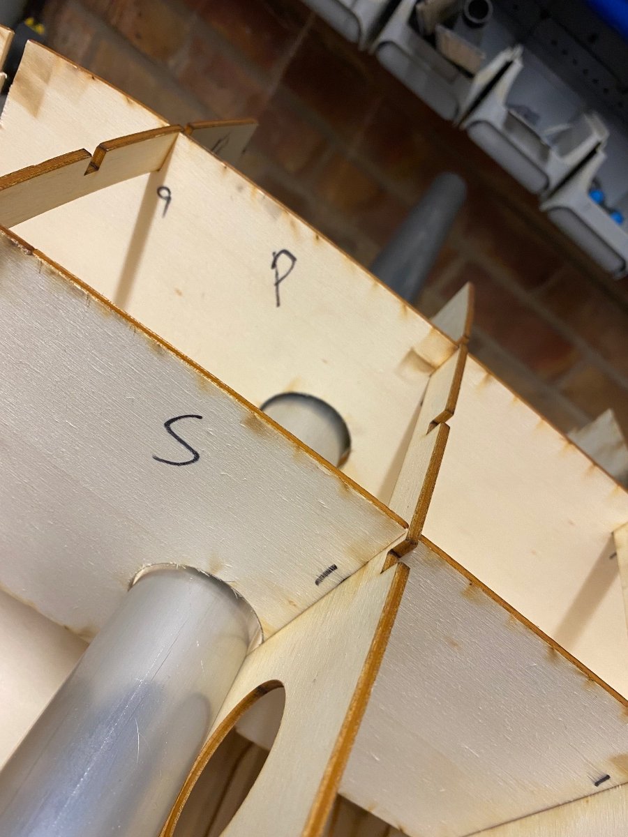
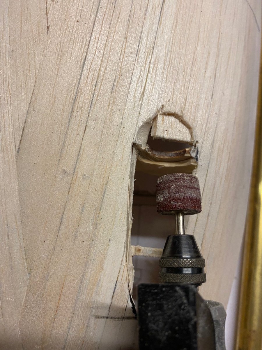
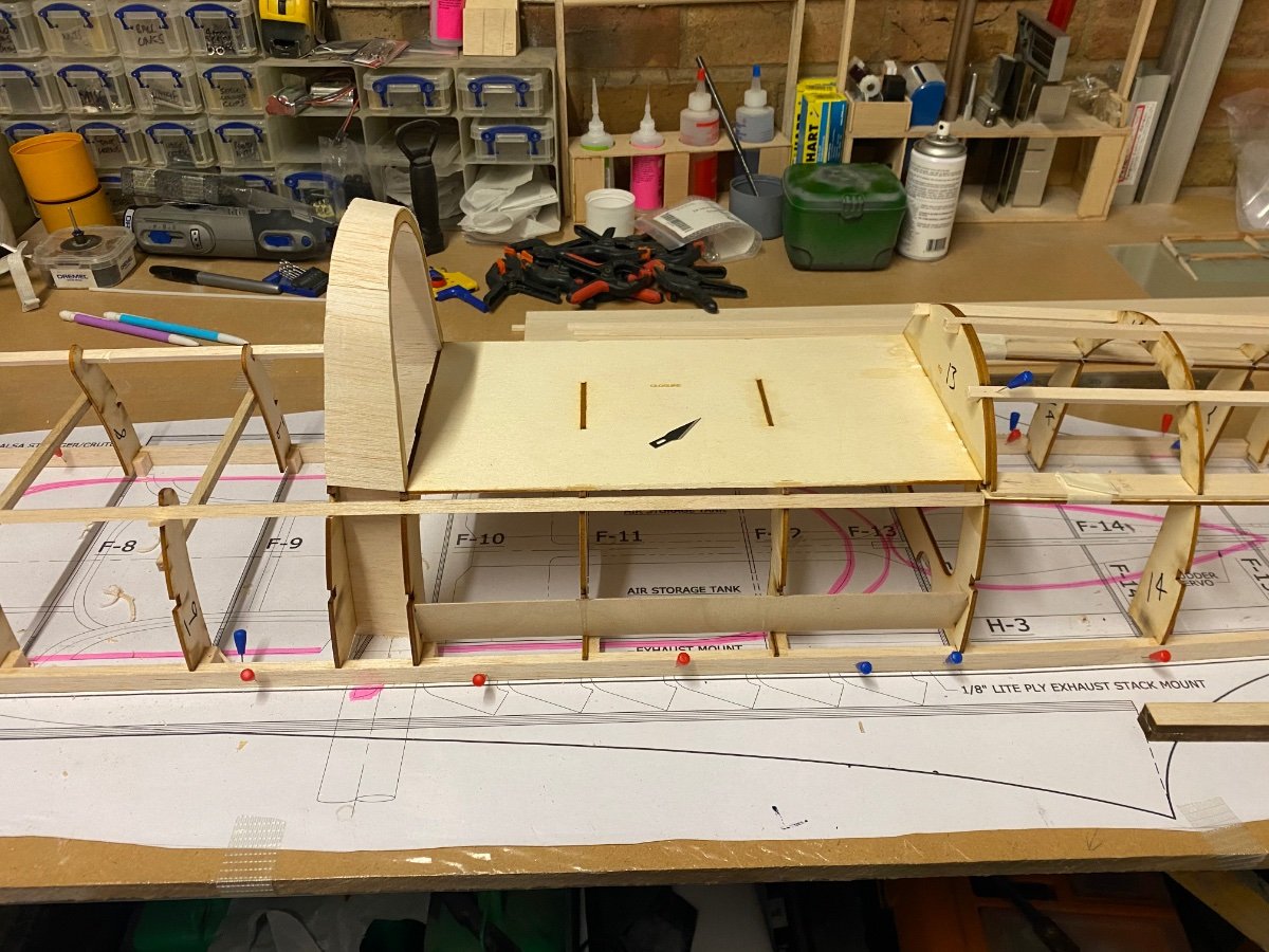
A dry fit followed by gluing in place tonight took up quite a bit of time.
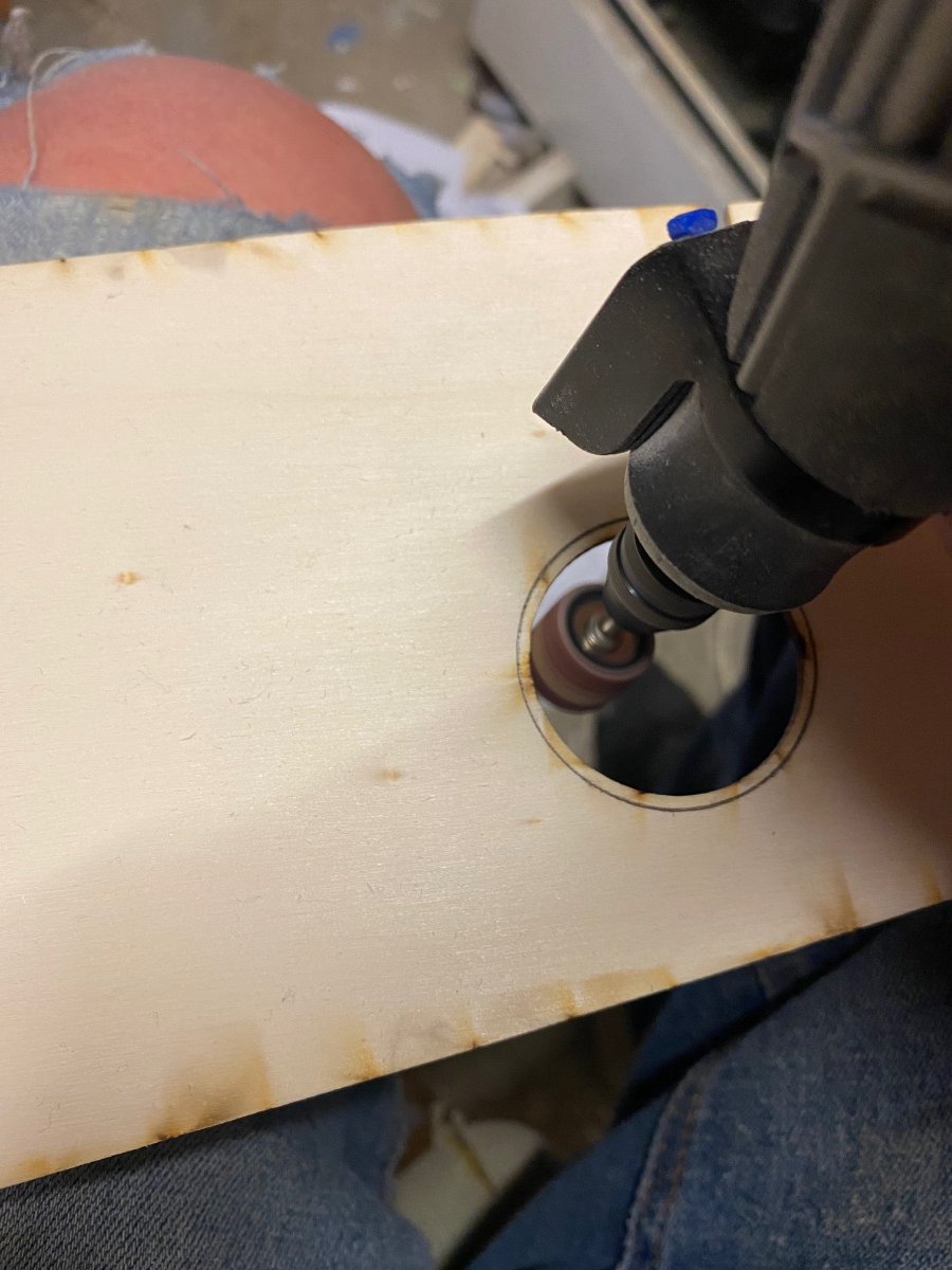
Again the tube section hasn’t been cut big enough so I will have to adapt it tomorrow. I have dremeled out the center holes and will leave the wing ribs as with the tail.It really is a solid section when all stuck together.
I’m just gutted I won’t be getting much further for a while as I’m waiting for the retracts from the states.
I can’t progress much further until I have the nose retract.-
3
-
-
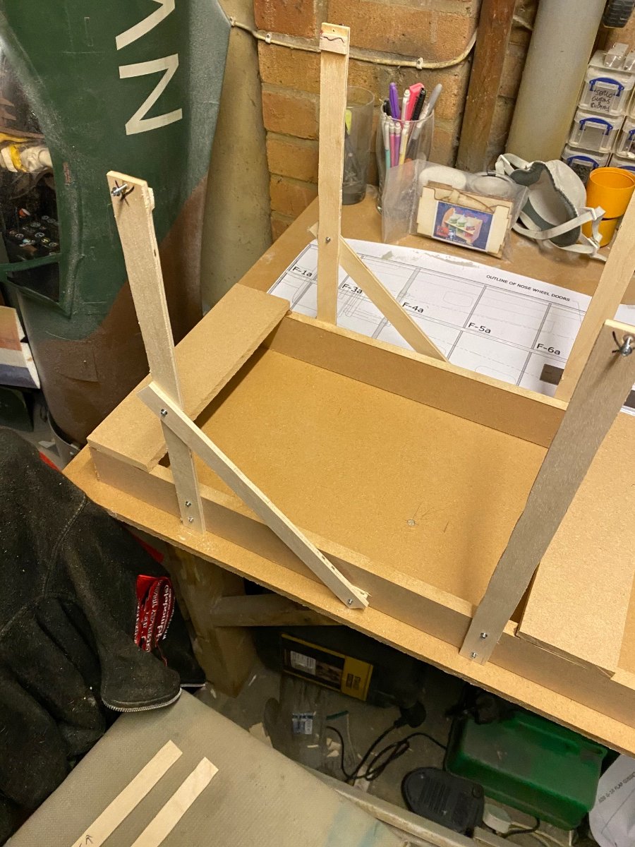
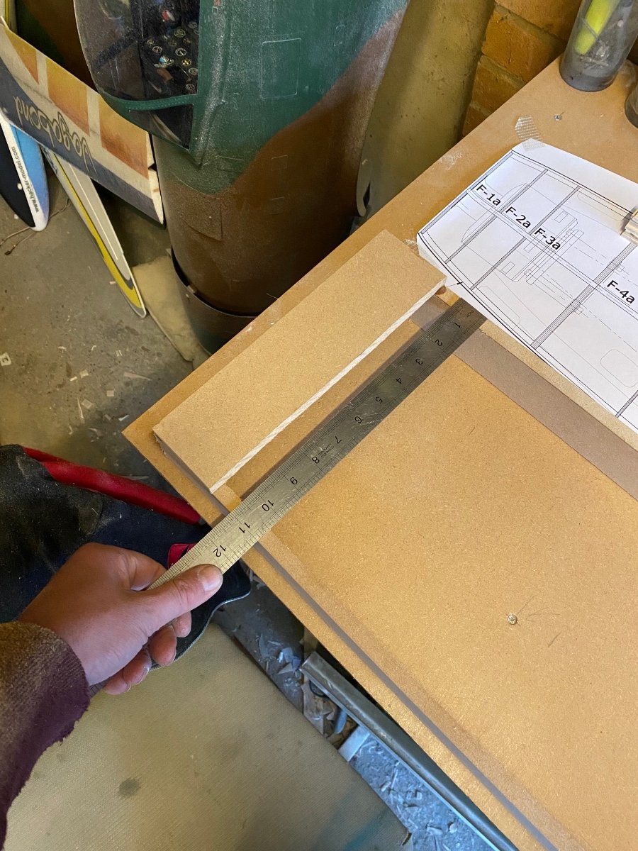
Feels like a non event when I make a frame to carry a part but it’s essential of course.
Can’t wait to start closing this up this week ??-
2
-
-
55 minutes ago, Martian said:
Excellent work
Thanks Martian ?.
-
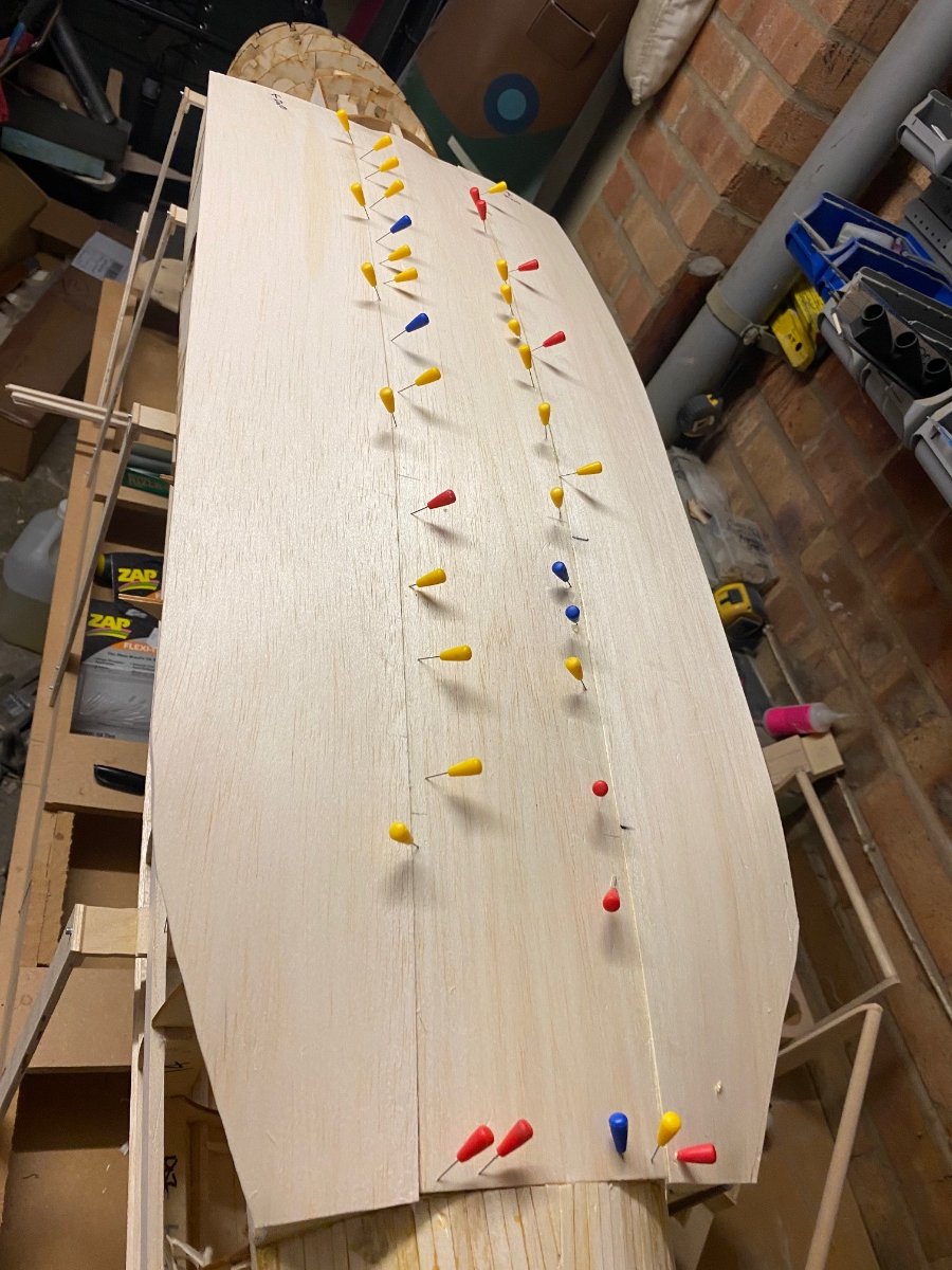
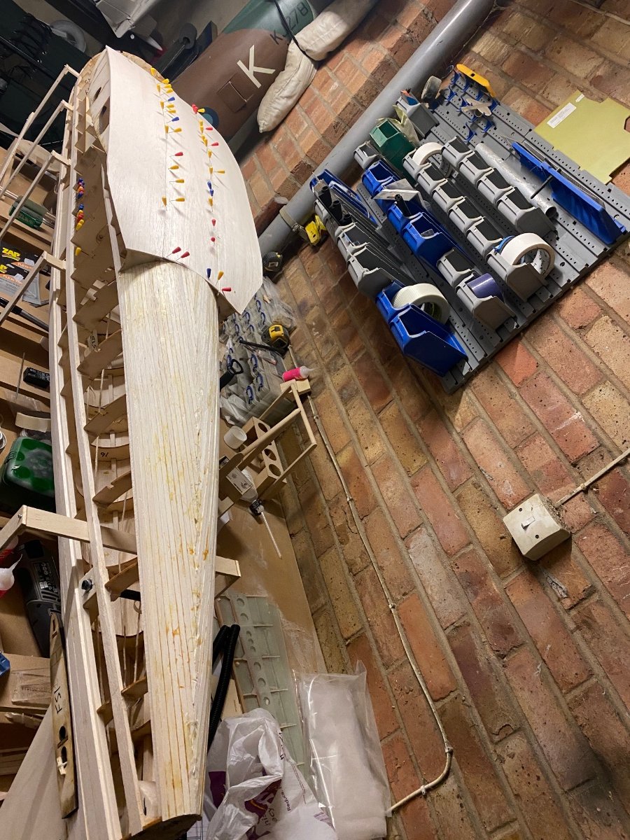
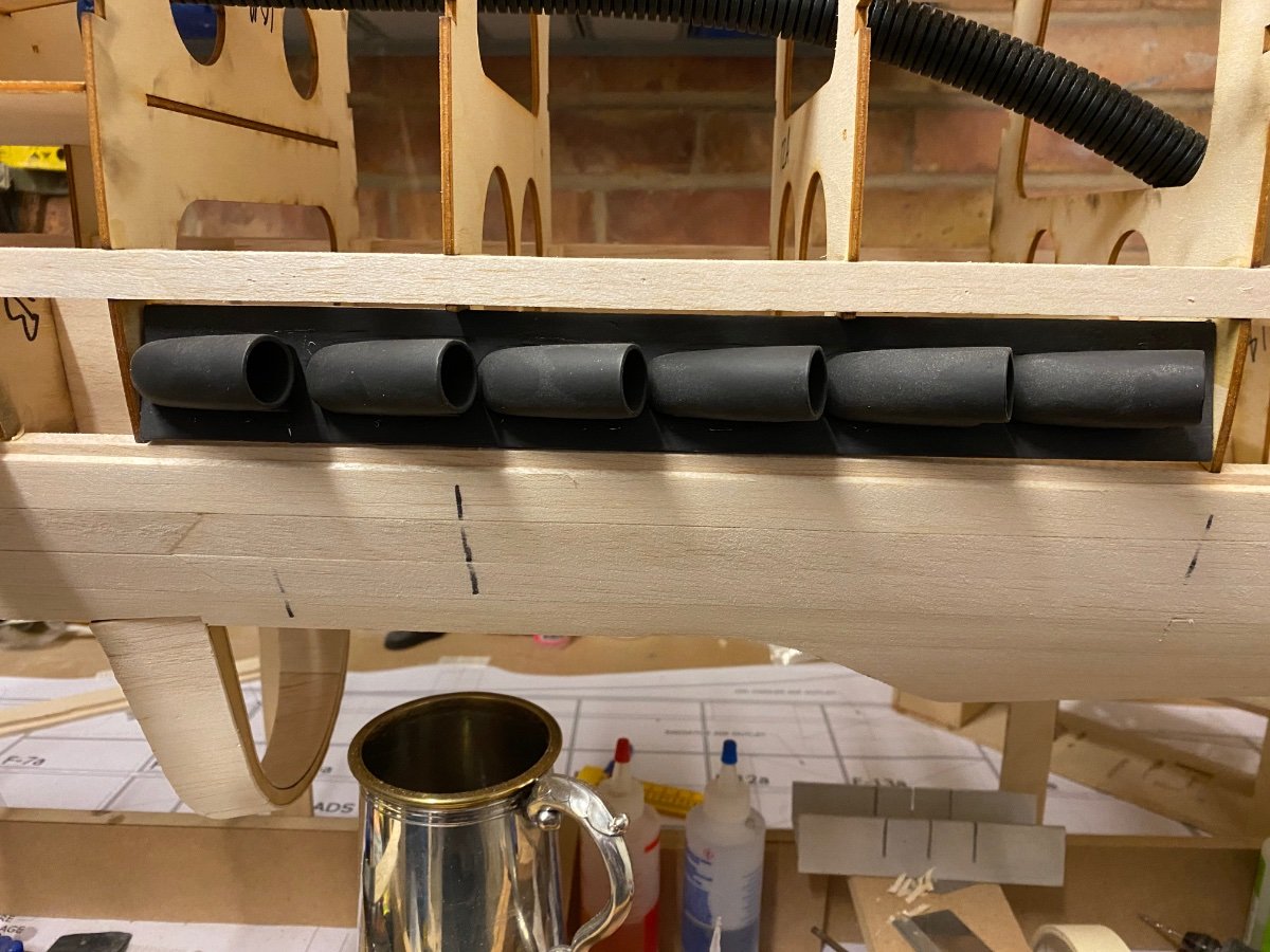
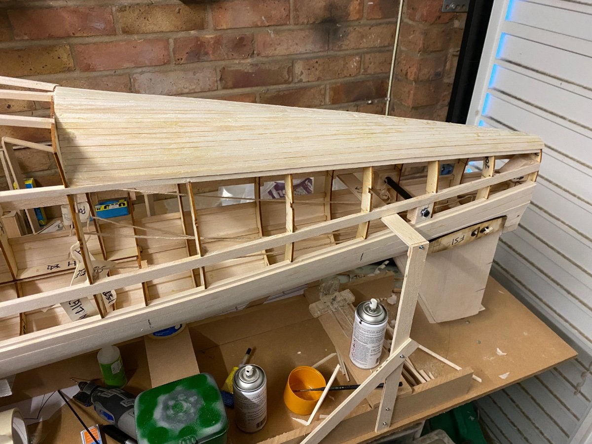
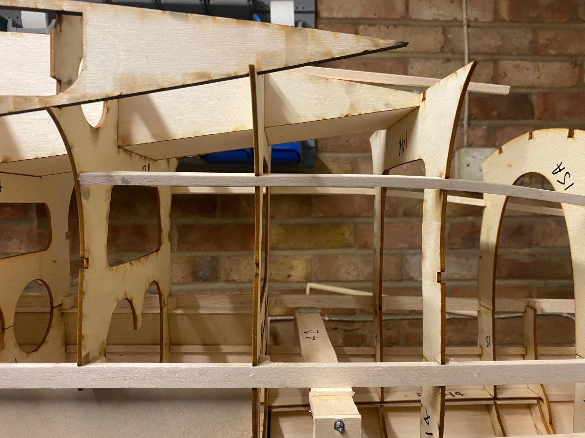
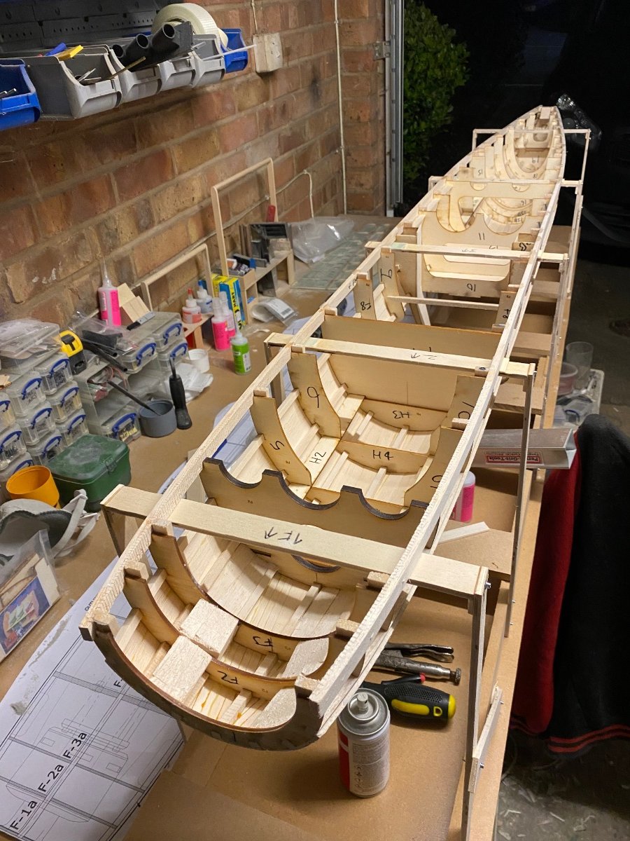
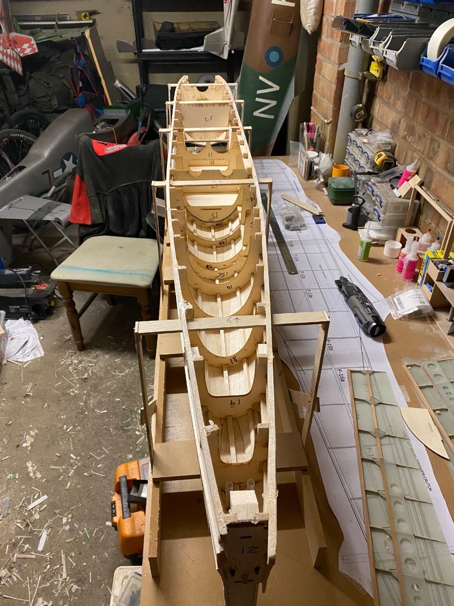
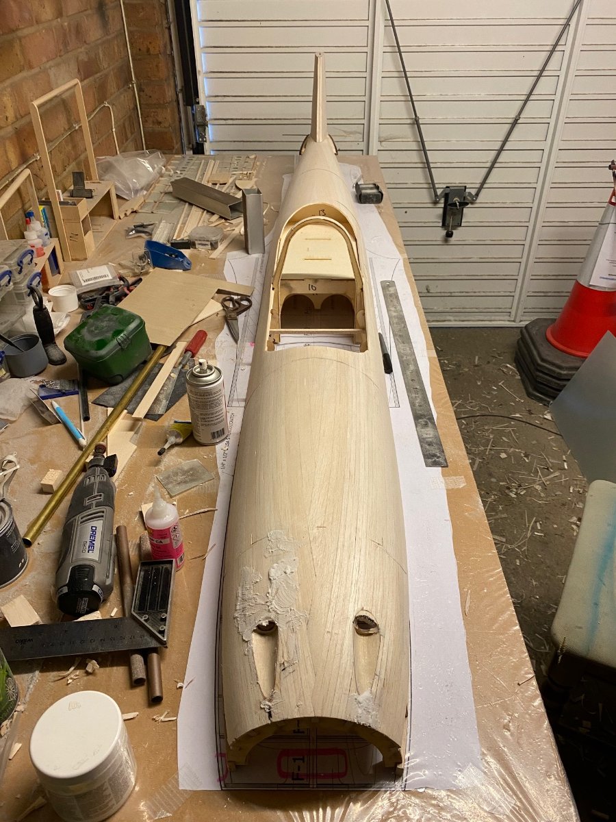
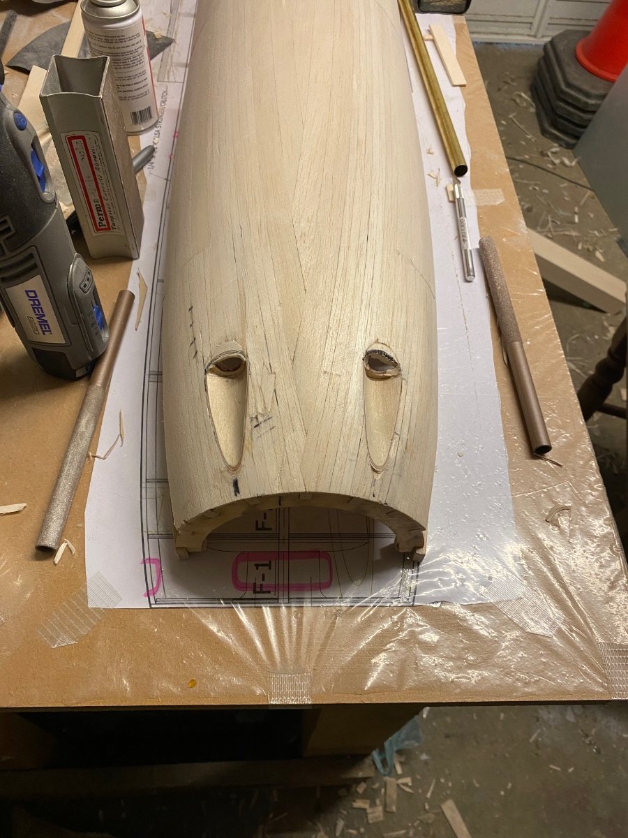
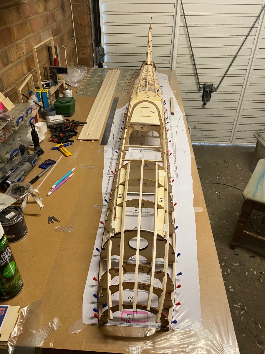
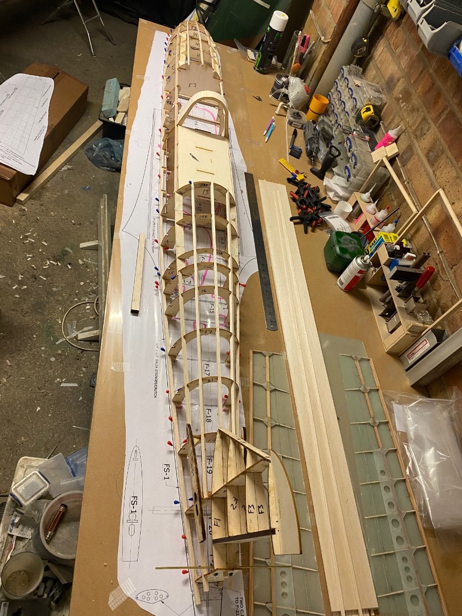
Haven’t posted for a while so here’s where I’m at.
I’ve planked the top fuz but left a gap as I have to make a frame to hold it upside down.The nose guns have proven to be a pig! The recesses in the formers are not even close for a 5/8” tube so I ripped off the ply and started again.
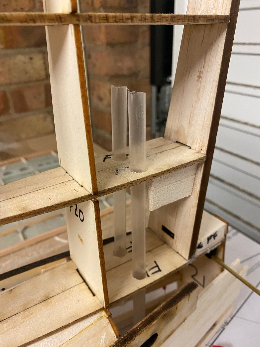
I’ve added tubes in the fin for lights as this model will be fully lit.
The fairings for the tail are also tricky and I will be doing more work on these when the whole plane is sheeted.-
7
-
-
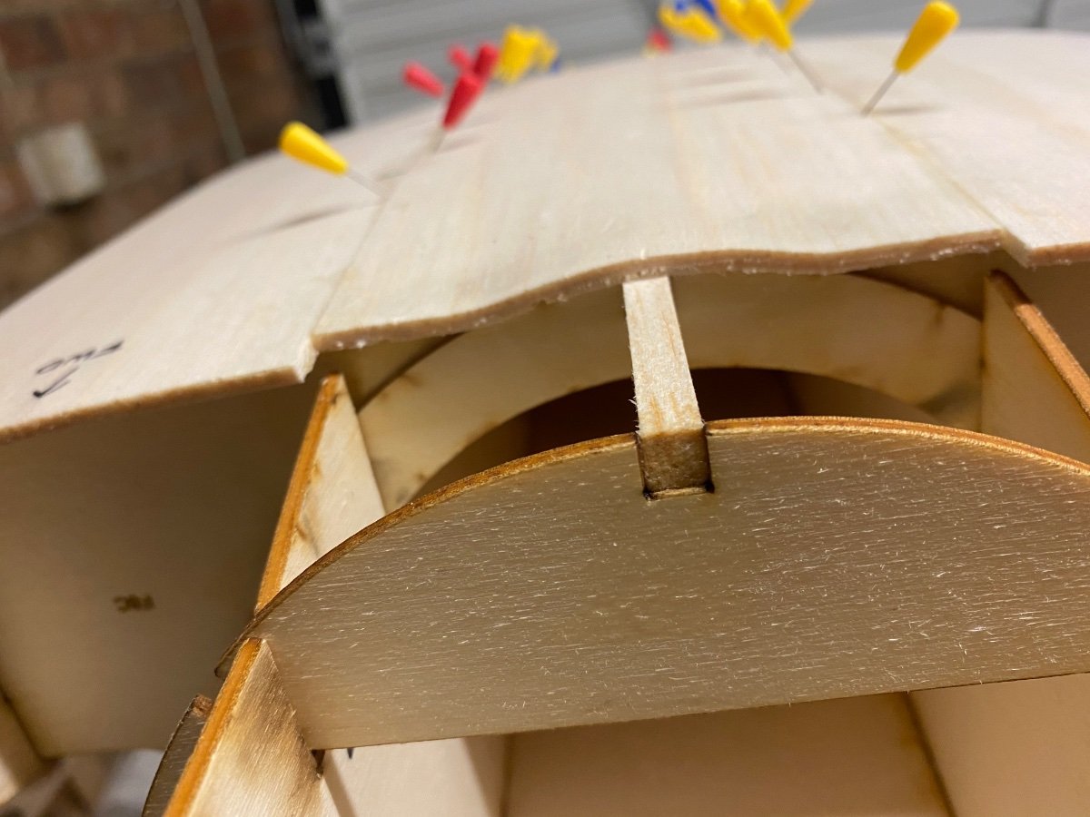
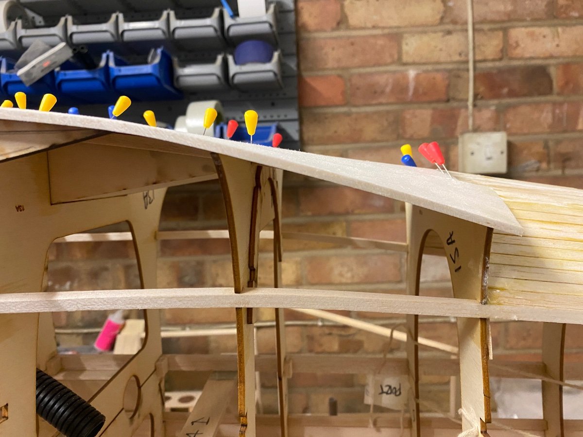
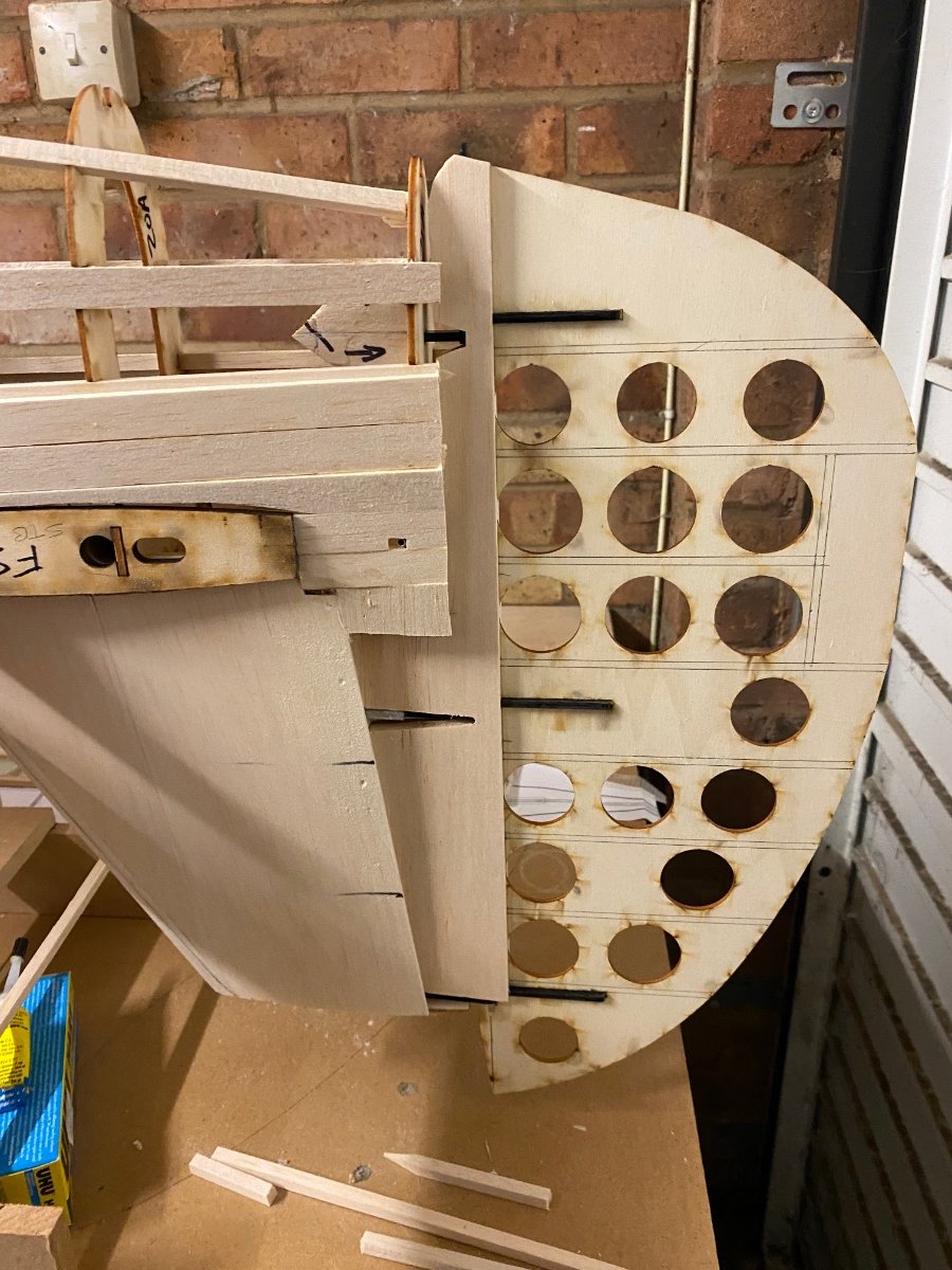
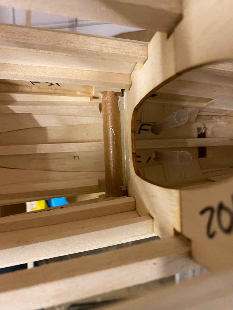
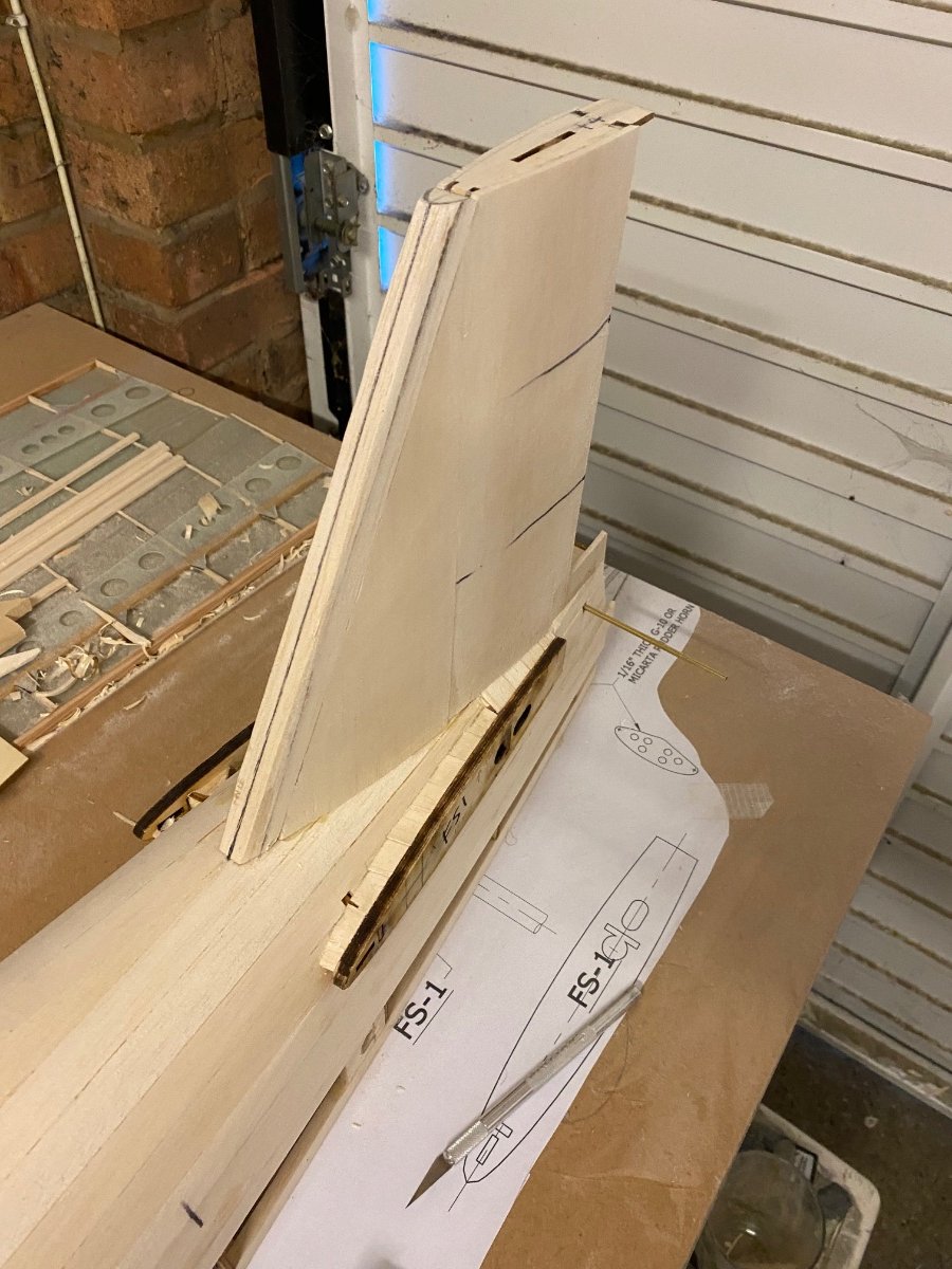
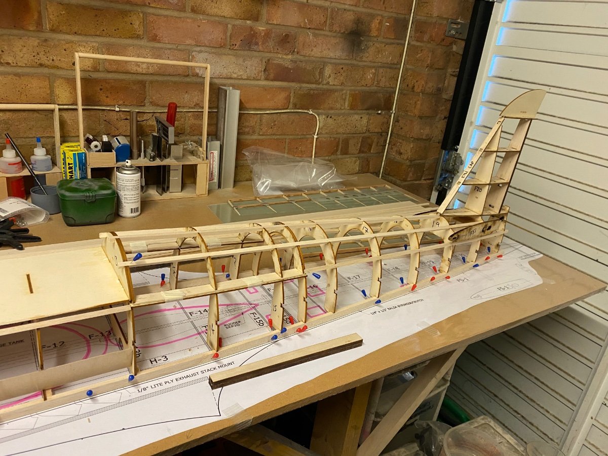
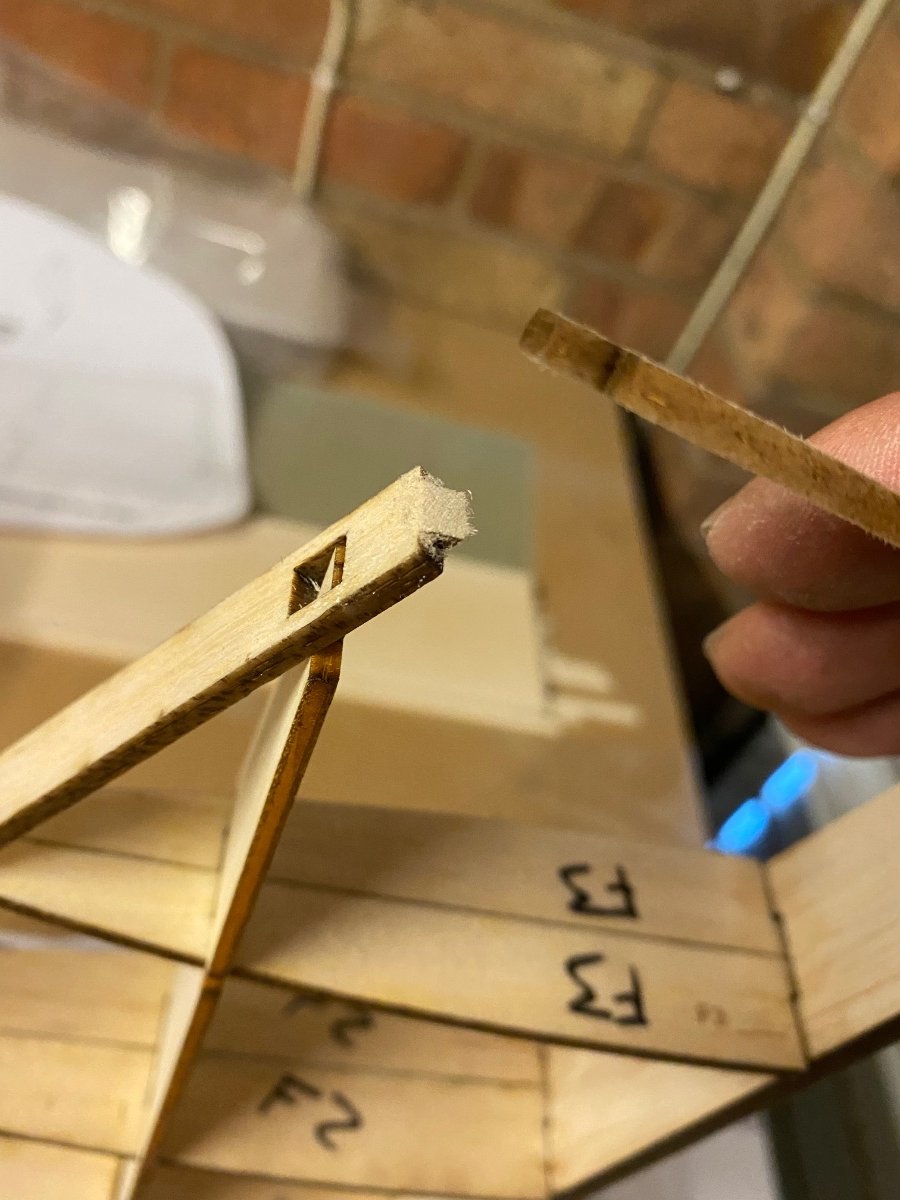
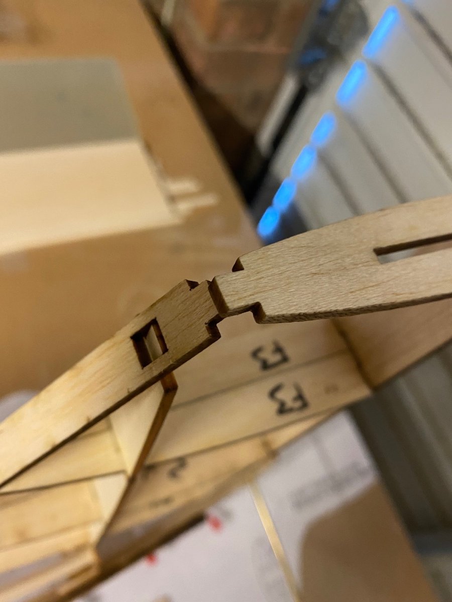
Good progress today but I’ve had to stop early as still not feeling great.
A few issues dealt with which I’ll be passing back to the relevant people to make the next persons build easier.A few parts are tongue to tongue instead of tongue and groove (easily solved).
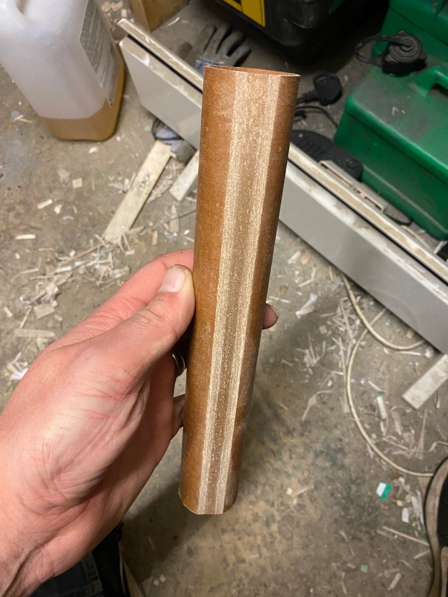
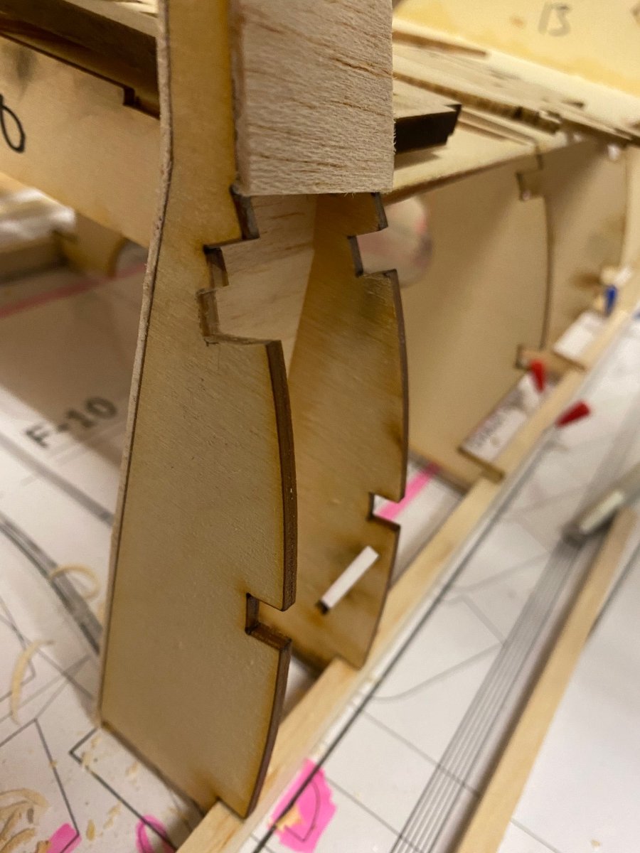
Had to sand the phenolic tube to fit tight against the fin post.
Fin 1 former did not sit on the stringer as designed and the cut in the last former is 1/4” above it, again an easy fix.Next week I should be able to start sheeting this part but it will be tricky. It will be a mix of planking and sheeting as it has some tight curves front and back, it’s also tricky around the fin and stab.
Can’t wait.
-
4
-
-
1 minute ago, Martian said:
loving this build
Thanks very much Martian, very much appreciated ?
-
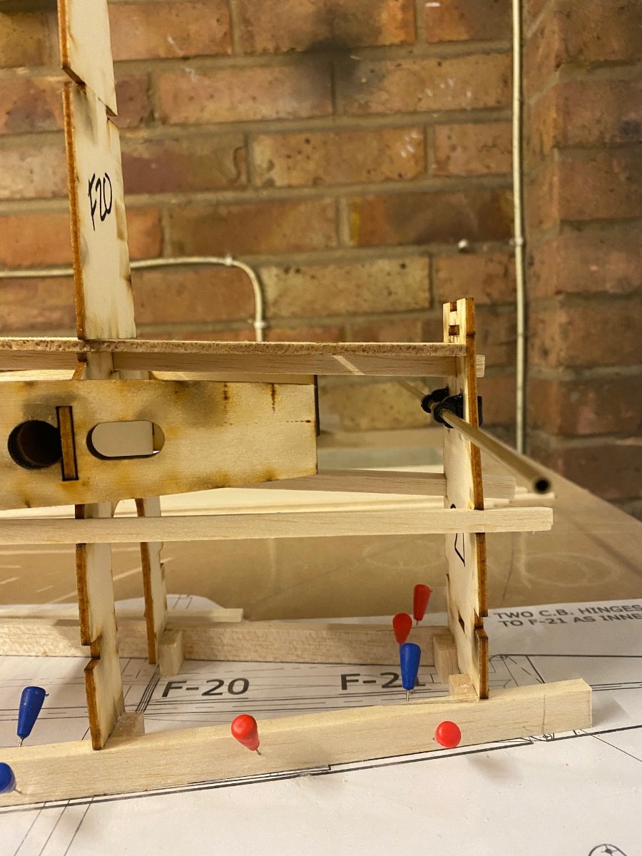
Took a hit to progress last week as I’ve been ill and only got out of bed today.
Anyway, I’ve made some progress today and will post some decent pics when the workshops had a good spruce up tomorrow.I’ve encountered a few issues along the way, some formers are too big dispite being cut as per plan & some are too small (you can see this where the stringers are not flush with the formers).
It’s easily resolved but annoying and time consuming.
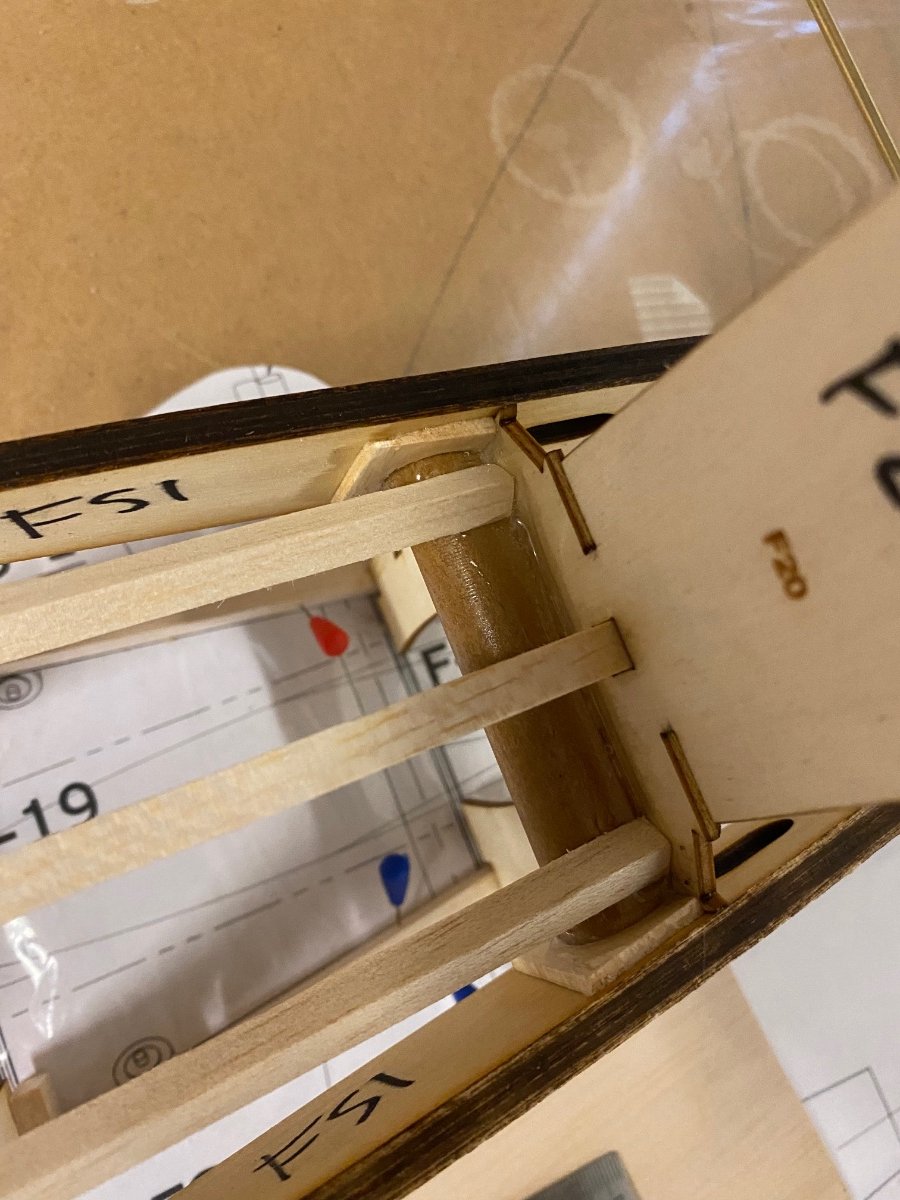
I’ve also had to butcher one of the formers as it’s significantly out.The tail wing tube is tight against the fin post and the ribs are just cut for the ally tube and no the phenolic tube (same with stab).
On the fuz this isn’t a major issue as I’ll just cut the tube to suit.
On the stab it will be an issue and something I’ll have to address once the fuz construction is complete, I may be able to open them up with a step drill but some of the ribs haven’t got much meat to do this.Lastly, the balsa stringers are playing game and with a few slots on the backside there meeting the curves lovely.
-
1
-
-
1 hour ago, Danny Fenton said:
Thats a pretty keen price too ?
I thought it was ok mate ?
-
27 minutes ago, maurice northcott said:
Ah right, Thank you for that info mate
Cheers
maurice
No probs mate ?
-
 1
1
-
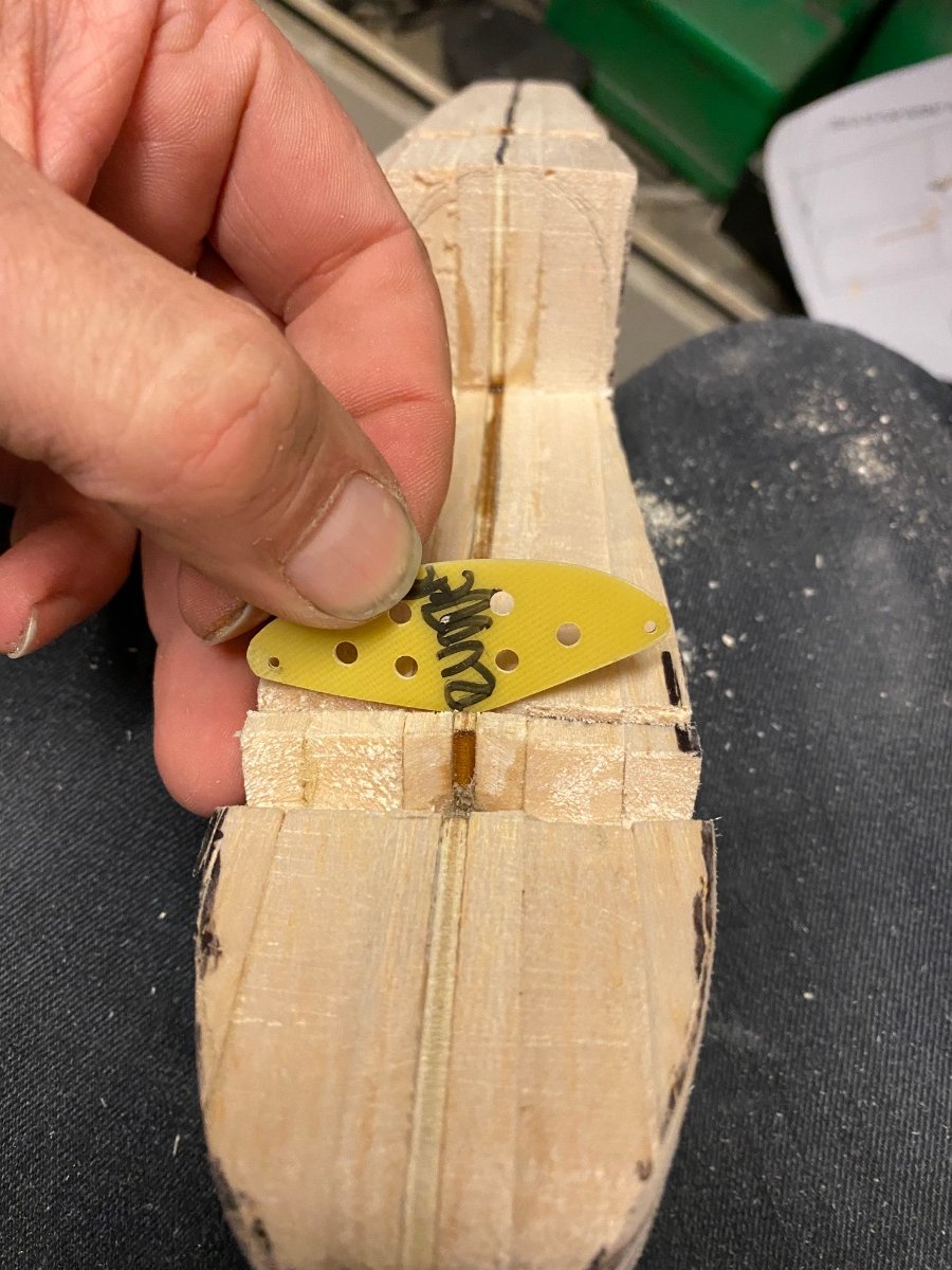
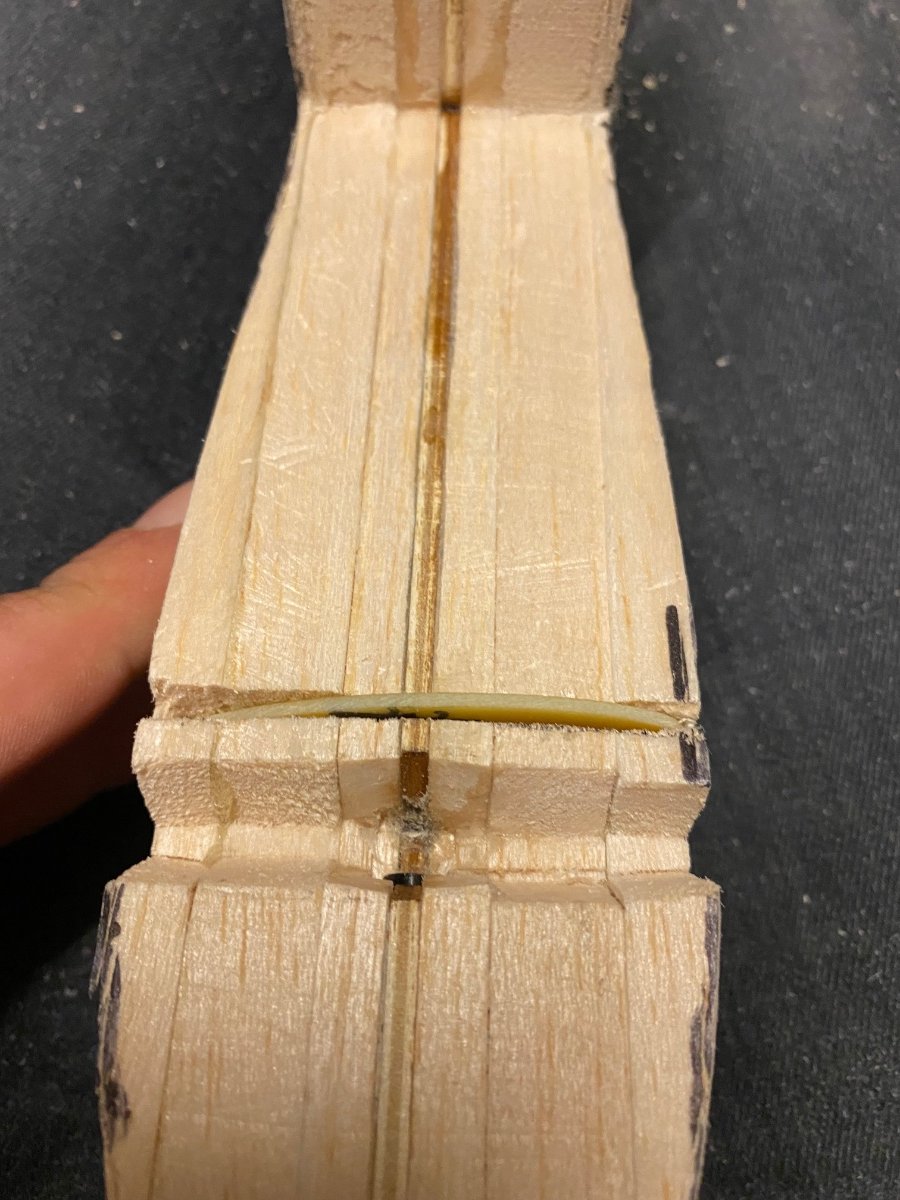
-
1 hour ago, maurice northcott said:
Nice work Craig.
From where did you source your G10 please - the reason I ask is because you seem to describe thickness in terms of thousandths (of an inch, I guess) whereas most suppliers seem to describe thickness in mm? I apologise if you have already given this info in the thread.
Cheers
maurice
Thanks Maurice,
I got it from;
https://www.aiplastics.com/products/industrial-laminates/epoxy-4w-ep.html
It’s labelled as 4W/EP which is essentially the same thing.
These guys cut the material to your desired length as well. I referred to the thickness in imperial as it’s an American plan and that’s what’s detailed, I just converted imperial to metric as that’s what the company uses.-
2
-


1/4 scale electric Bell P39 Airacobra build (designed by Jerry Bates)
in Building from Traditional Kits and Plans
Posted
Thanks very much ??