


Martyn K
-
Posts
9,025 -
Joined
-
Last visited
-
Days Won
1
Content Type
Profiles
Forums
Blogs
Gallery
Calendar
Downloads
Posts posted by Martyn K
-
-
I am still putting the calendar together but our events for 2024 are as follows: There is a reasonable chance that we will have one more event in the NW, south of Manchester. More details to follow.
UKCAA @ Buckminster
BMFA Buckminster
10 May 202410:0010 May 2024Note that this is a FRIDAY event.
Usual format, fly-in morning and afternoon plus Pick5/7 over Lunch
UKCAA @ Ivel MAC
Bedford
19 May 202410:0019 May 2024Our first visit to Ivel MAC
Location details to follow
UKCAA @ Buckminster
BMFA NFC Buckminster
28 Jun 202410:0028 Jun 2024Note that this is a FRIDAY event.
Usual format, fly-in morning and afternoon plus Pick5/7 over Lunch
UKCAA @ Retford
Retford MFC
21 Jul 202410:0021 Jul 2024Steve Dunning Memorial Day
UKCAA Fly-in only.
No contest but awards (for Members) for Pilot's Pilot and Concours d'Elegance
Visitors welcome but must pre-register
UKCAA @ Buckminster
NFC Buckminster
20 Sep 202410:0020 Sep 2024Note that this is a FRIDAY event.
Usual format, fly-in morning and afternoon plus Pick5/7 over Lunch
-
The plan for the Hanno Mystic was never released. It was kitted as the Mystic 60/90, but as far as I know, no plan was produced for general release.
The Mystic 60/90 has a tail moment ratio than the Mystic 30, the tail volume is different apparently.
-
It flew really well. Stephen always brings some of the most interesting aircraft to the NW Area Indoor at Rochdale. Very creative.
-
 1
1
-
-
My first kit was a KK Soarer Baby - 1970. Not very successful as I painted it in coloured dope rather than shrinking dope...
However, what got me interested was a home design 'hang glider' which used a polystyrene apple tray for a wing and fishing lead tied to 4 corners but slightly forward of centre. Slope soared it off the edge of a cliff and amazingly it flew - quite well..
-
1
-
-
Deffo a flair meteor or possibly a meteorite. There were 2 versions of the Meteor, 40 sized and a 60 sized. The Meteorite was IIRC for 20 sized motors. Those wheels look big for a Meteor
-
1
-
-
I'll remember that, thanks Matt
-
You are a star 🌟 🌟 🌟 🌟 .
Many thanks, i would never have guessed small can be beautiful.. 😂
Martyn
-
Hi all
Many moons ago, BEB (RIP) had a thread running about scratch building a drone.. Using a Wii clone controller iirc.
I am blowed if I can find it.
Anyone here have it bookmarked?
Thanks
Martyn
-
On 01/03/2023 at 22:39, Nick Cripps said:
A piece of plasterboard on that table would make a good building surface, Dave 😉
That's what I use but give it a coat of emulsion first to seal the dust...
-
Seychelle plan is here. https://outerzone.co.uk/plan_details.asp?ID=11120
I agree, one of the loveliest designs. I built the same kit (in 1981) that Andy Green has. The wing section on the plan has a vicious stall, the model needs to be flown fast. I keep threatening on building another but I'll probably use a wing section that is a bit more 'me' friendly.
-
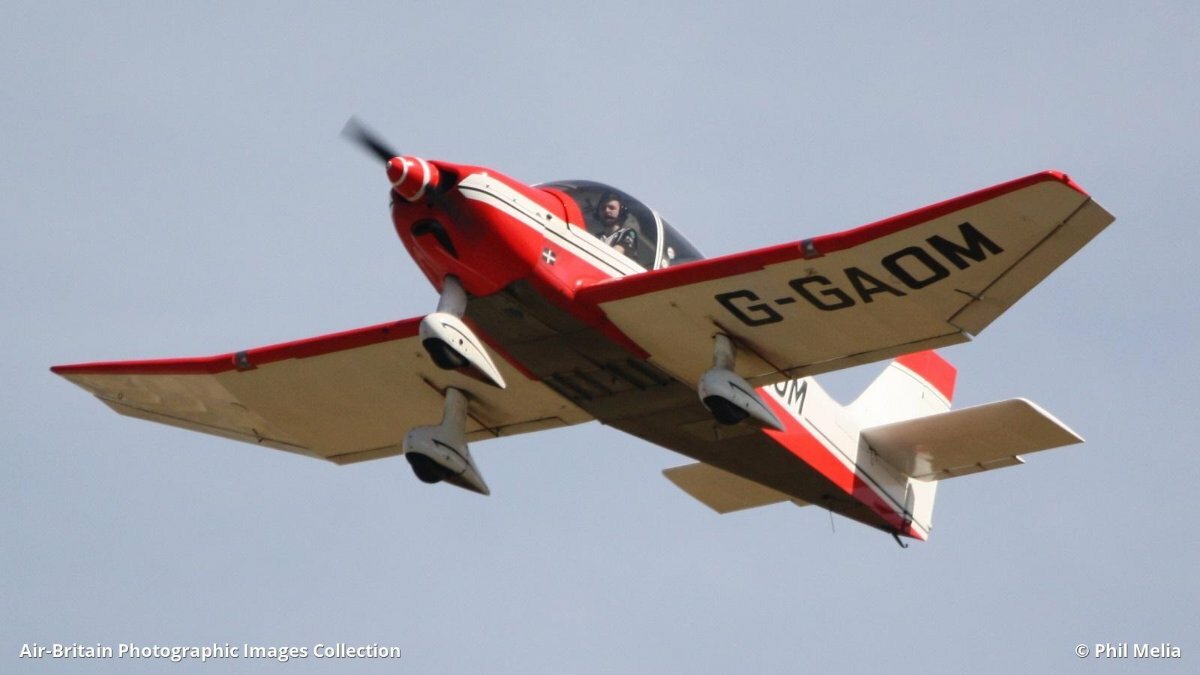
It really is about time that I updated this. I had a lousy winter building season, the fracture in my back 'moved' in November and bending over a bench was a very short lived affair. It didn't help that my SD card in my phone died and I have lost a number of photos (about 3000). <sigh>
However, the Robin has progressed slowly. The wings finished, covered and painted and markings applied (sorry lost photo).
Then started work on the interior.

Instrument panel was 3D printed than the dials were from the freebie that came with RCM&E a few years ago. (Hint - it would be nice if that could be done again, I cant print as fine as your printers).
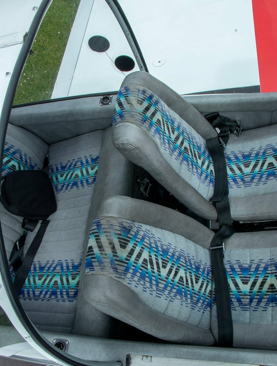
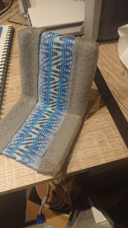
The seats were a bit of a challenge. They were cut from 9mm foam (B&Q) but sorting out that distinctive pattern was a challenge.
The best I could do was copy a part of the pattern from least distorted seat base, stretch it in GIMP then join the stretched parts in a chain. Printed using a cheapo inkjet printer.
The velour is felt from Hobbycraft.
So, two singles and a bench seat, fabricated and fitted.
I am really quite pleased with this. The cockpit rear wall is 1.5mm balsa with vinyl film, still attached to its backing, glued in place using 3M spray adhesive. This will hopefully stop it from going wrinkly. The floor and walls are covered in thin foam sheet (£1 A4 sheet) also from Hobbycraft.
Another shot. The gap between the front and back seats is too large.. I used the windows as reference but of course the window positions aren't quite to scale.
The pilot was 3D printed from a commercial file. Its not the best print I have ever done, its actually a glider pilot but I dont care about that too much
He looks a bit moth eaten but only because I overdid keeping the wall thickness as thin as possible to try and save weight. The seat belt clamps are a bit big - so probably are the seat belts as well.
A couple of dry assembly shots while waiting to fit the canopy..
and
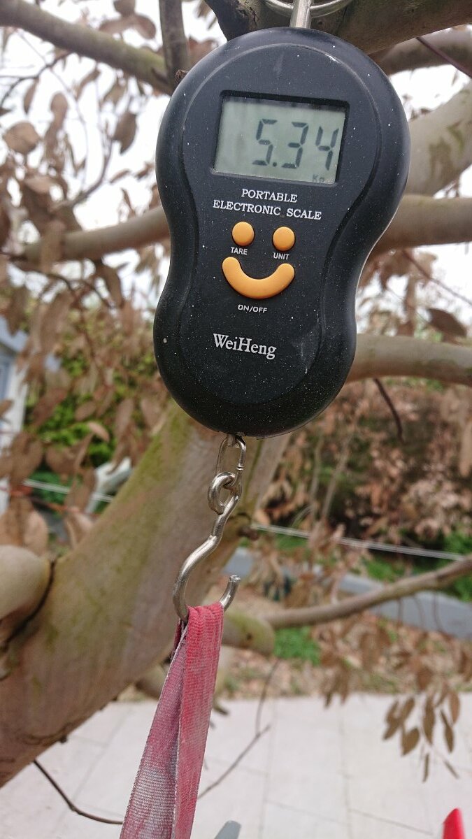
Getting it balanced was a bit of a worry. I needed to keep the weight under 5kg to qualify for BMFA light scale comps and it was already very close to that at this stage.
I fitted an onboard glow and fitted the C cell and the Rx battery in front of the crankcase. I still needed about 40g of weight to get the CG in the place marked on the plan.
A strip of lead was screwed above the crankcase but the model would still tip backward on its wheels. I couldn't do anything with the the undercarriage as the spats would prevent that from happening. I was also a bit nervous about the amount of travel needed for the all flying tailplane. I definitely didn't want a twitchy model. Another 40g of lead was added... 😞
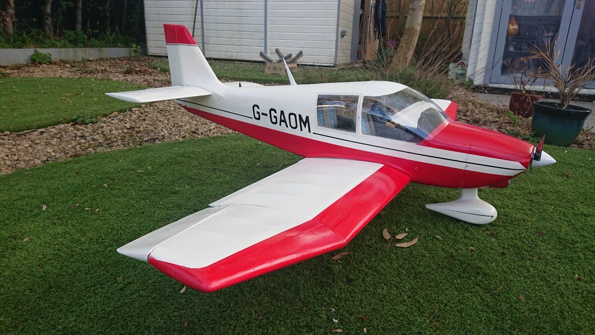
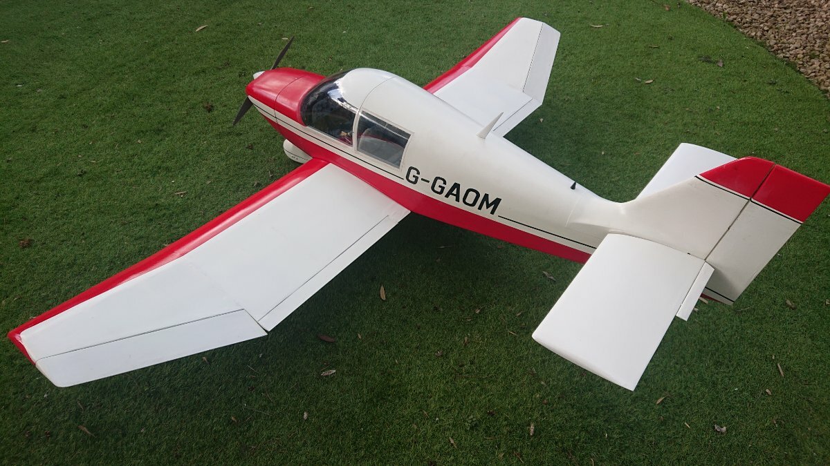
The canopy was completed with litho strips with obligatory pva rivet spots (got to keep Danny happy) and a final assemble photo.
and
The wing walkways have been subsequently added.
The spinner needs to be red with a white spiral but that can wait.
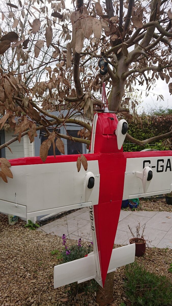
Time for the grand weigh-in..
Suspended from a tree in the garden, it weighed this much..
Drat and double drat Mutley, foiled again.
So its now a candidate for BMFA Flying only..
Two failed attempts at a Maiden. The first, the engine started and ran beautifully but the nose leg linkage was flexing too much (offset noseleg) so back to get that fixed. I tried again on Sunday at the NW Area Scale Fly-in but a leaking fuel tank put paid to that effort. Now waiting for a replacement tank. One of the joys of using NIB 25 year old hardware.
-
7
-
-
Reminder that this event is on for next Sunday, the 21st May.
Admission is £10 for pilots. Spectators and helpers are free.
Hope to see you there.
-
The BMFA North West Area in conjunction with the Shropshire Model Flying Club will be holding the 2nd Annual Scale Fly-in on Sunday the 21st May 2023. This is a fun event catering for all types of scale models.
Prizes awarded for the best turned out model, the best pilot and the best 'small' model (approx. .30 ic or equivalent electric).
BBQ will be laid on.
Numbers are limited so please pre-register by email: [email protected]
Location: 52.74291922604198, -2.8517608708386883
SMFC entrance gate – What3words location : ///cackling.distilled.fears
-
UK Classic Aerobatic Association
The UKCAA will be holding 5 events in 2023. Details will be published in the UKCAA events forum.
For 2023, there will be no membership fee. We are having a free year. 🙂
If you would like to join, please download and return our membership application form from: http://www.ukcaa.org.uk/Club/Joining.aspx
Note that we have now moved our members database to the BMFA Members and Club portal. The required email address on the form must match the email address on the portal. BMFA membership is mandatory.
While you are at the UKCAA website, have a look at the plans and articles that we have provided.
http://www.ukcaa.org.uk/Club/Plans.aspx
and
http://www.ukcaa.org.uk/Club/Articles.aspx
All under 'Association Information' dropdown..
-
Thanks all.
That appears to have worked. I proved it by binding in the order selected. One thing that i had to do was to connect them separately. I initially tried to bind with the satellite connected to the s-port on the rx8r. That didnt work.
Next, I bound them as suggested, individually. To prove they had worked, i then powered up the receivers individually and they both appear to still be bound, i still had telemetry on the rx8r amd when i connected the satellite, the lights indicated that it was bound.
I originally was expecting to see two receiver options in the setup, perhaps rather naively.
Great result, many, many thanks
-
Thanks for the thoughts and suggestions.
To answer Phils question. Only one receiver shows up (the RX8R pro) when I bind with telemetry on channels 1 to 8 as normal. I cant see or undetstand how to bind a second receiver. It may be that the 2nd receiver binds automatically as it is plugged into the first but if so, there is no way that you can then set the telemetry or failsafe for that receiver. Perhaps if i try binding the slave first then something may happen.
I dont want to put the rx8r at the rear of the fus as that would mean long extension cables for power and the servos plus the real problem of accessing and managing that receiver.
I am starting to think that perhaps opentx doesnt support this scenario, its only supported in the frsky proprietary software.
-
Hi all
Horus 10S Express Transmitter with OpenTx
Rx8R pro Receiver 1
R-XSR Receiver 2
I need to fit a satellite receiver (R-XSR) to my existing Rx8R Pro as the main receiver is shielded by all the metal panels. I understand from T9 that this is possible.
The R-XSR is connected to the Rx8R Pro using the SBUS channel.
I can bind the Rx8R without any problems but I haven't got a clue how to bind the second receiver and (apparently importantly), disable the telemetry from the R-XSR.
Any suggestions please? I have googled and failed.
Thanks
Martyn
-
I am off to Malta for the first time in early May. 4 days in Malta, the rest on a short Med cruise for my wife's 70th birthday pressie. Quite looking forward to the Malta bit. I would pass on the cruise if I could although most days we are on dry land so that is some form of redemption.
-
1
-
-
That looks amazing...
-
Very interesting Simon
An how-to article for RCM&E (or the website) would be very useful...
-
Thanks Gary. I am going to write to the current registered owner but I suspect that you may be correct..
-
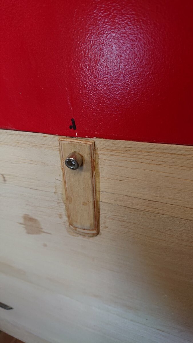
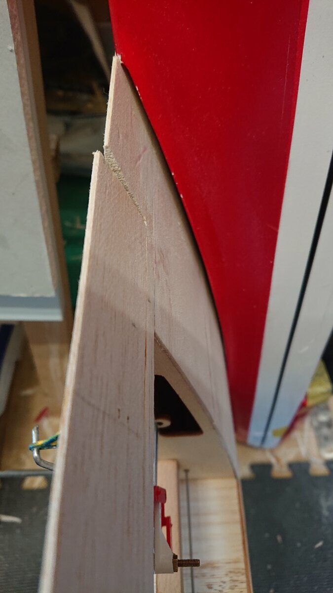
The wing mounting was fairly straightforward. Originally the kut had a laser cut ply sub former that carried two nylon wing bolt mounts. However, because i have modified the interior, i couldn't use this so had to settle for a single m5 steel bolt through the te of the wing. This was reinforced with a small ply plate. The Tee nut sits in a 6mm ply plate bonded to the gf fus at the end of the cut out area. If that makes sense..
Two dowels locate at the le. These are glued into the ply brace. All pretty traditional stuff.
A balsa wing fairing blends the gf fus into the lower wing root area.
Looks better after it was sanded down.
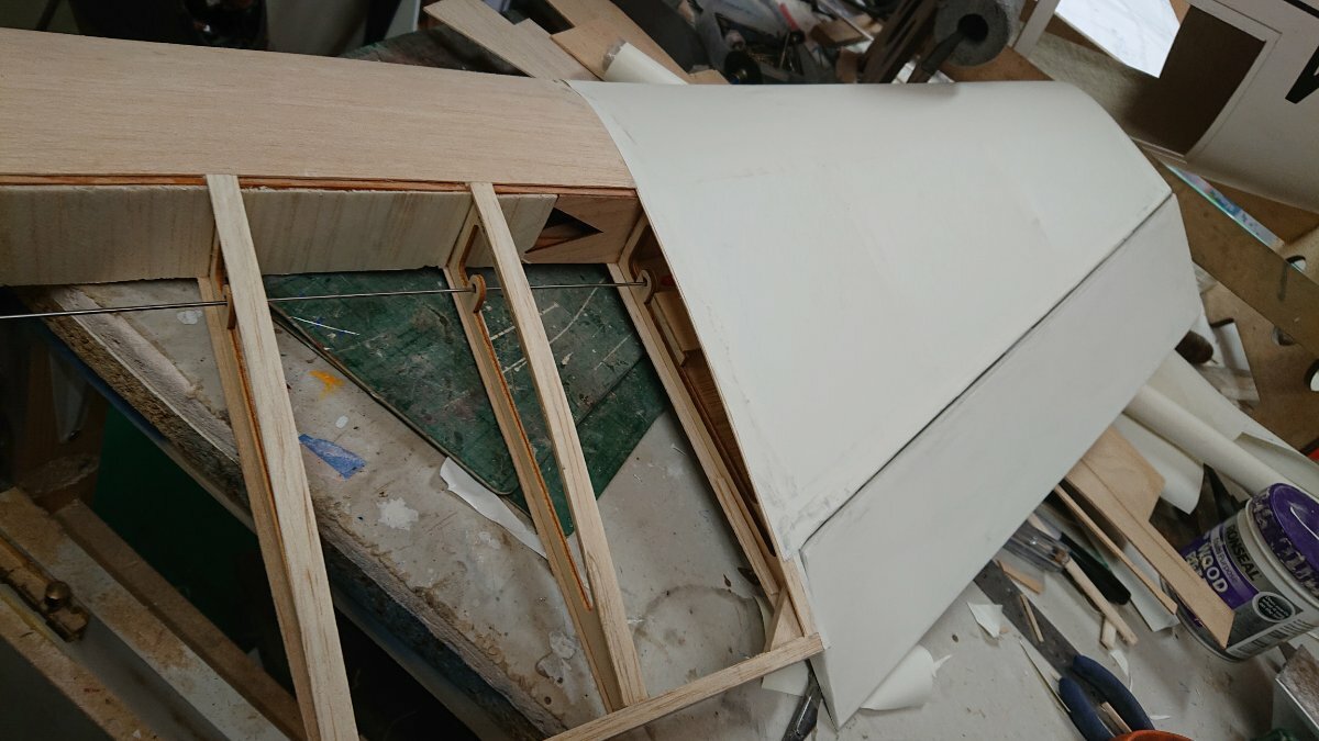
With that done, it was time for a dry assembly.
The gap to the wing fairings leaves a bit to be desired.
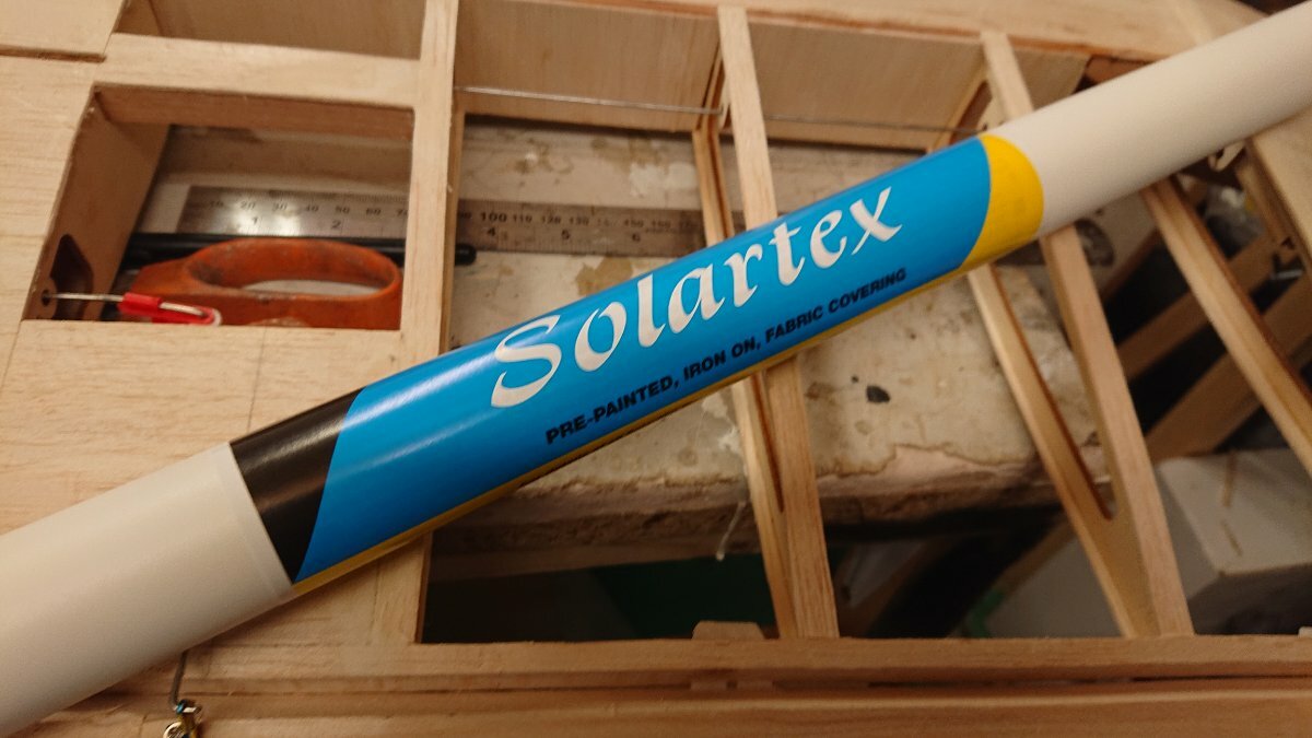
So, out with the solartex to cover the wing. Only 11 sq m left...
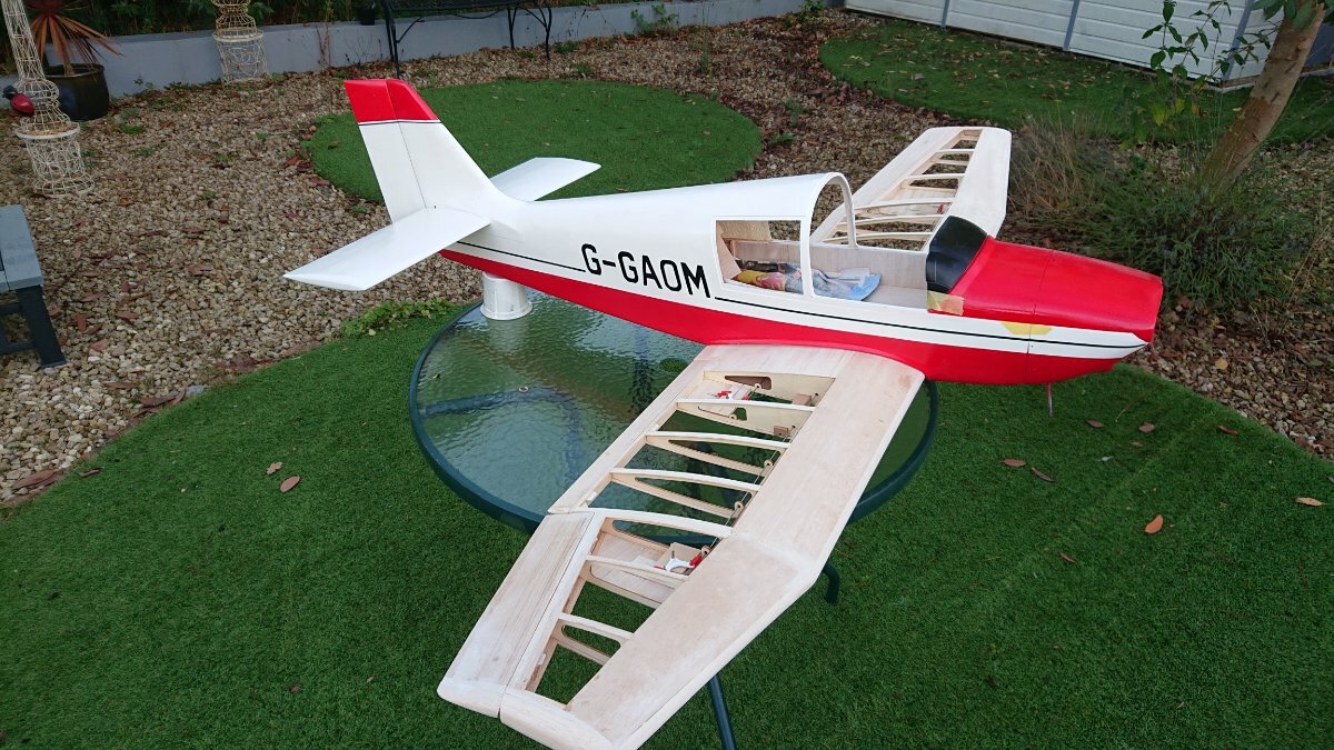
Wing now covered and painted white, i still have the red trim to do.
Now, if you are still there, can anyone suggest what has happened to the colour scheme under the wing root and fus looking underneath. I thought it was red, but it doesn't look very red to me..
I dont think its black either and its not shadow.. Very confusing..
-
Still slow progress. I can just about manage an hour or so standing in the workshop before my back complains too much.
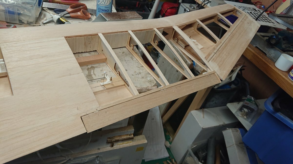
This weeks efforts have been fitting ailerons flaps and linkages which has taken far longer than it shoukd have.
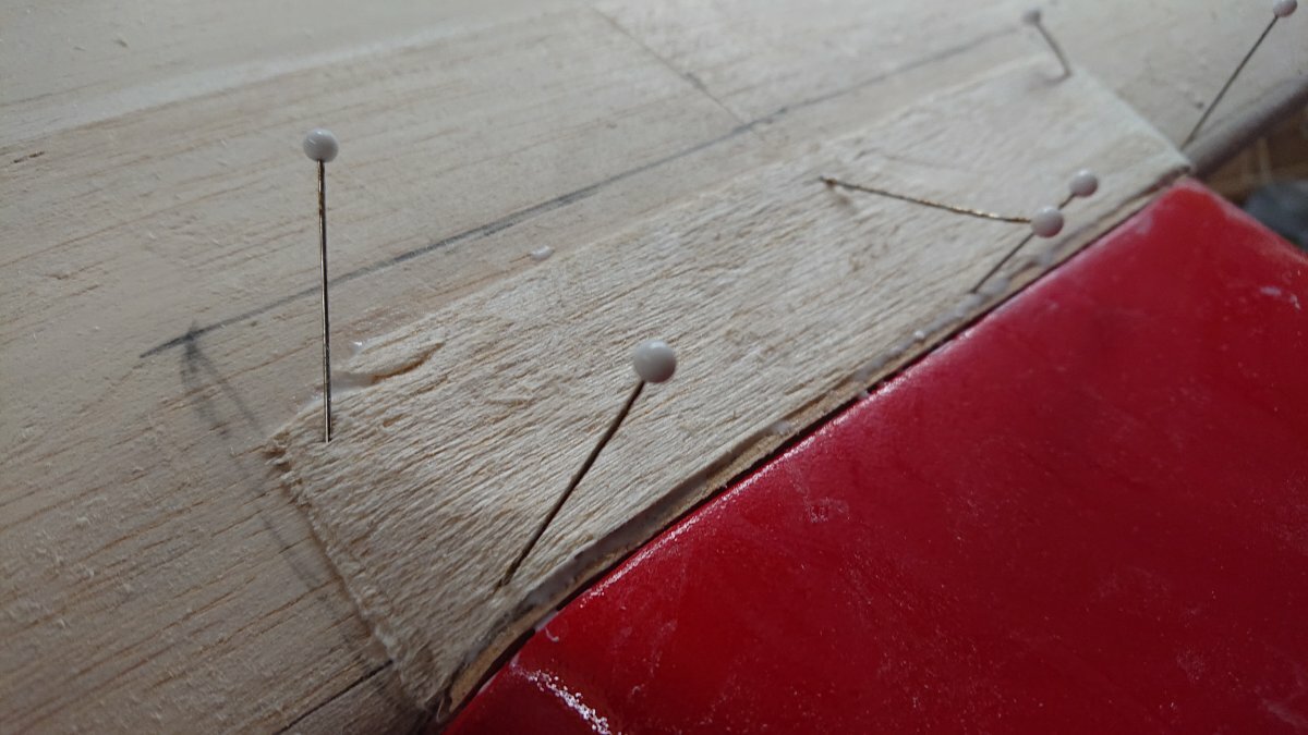
The hinging went fairly well for me with reasonable tight joints along the trailing edge although the dihedral break flap/aileron junction still doesn't look quite right.
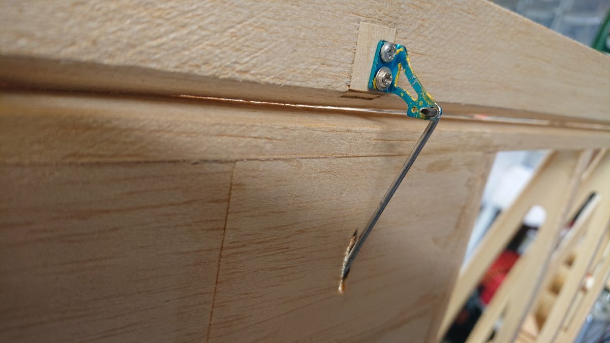
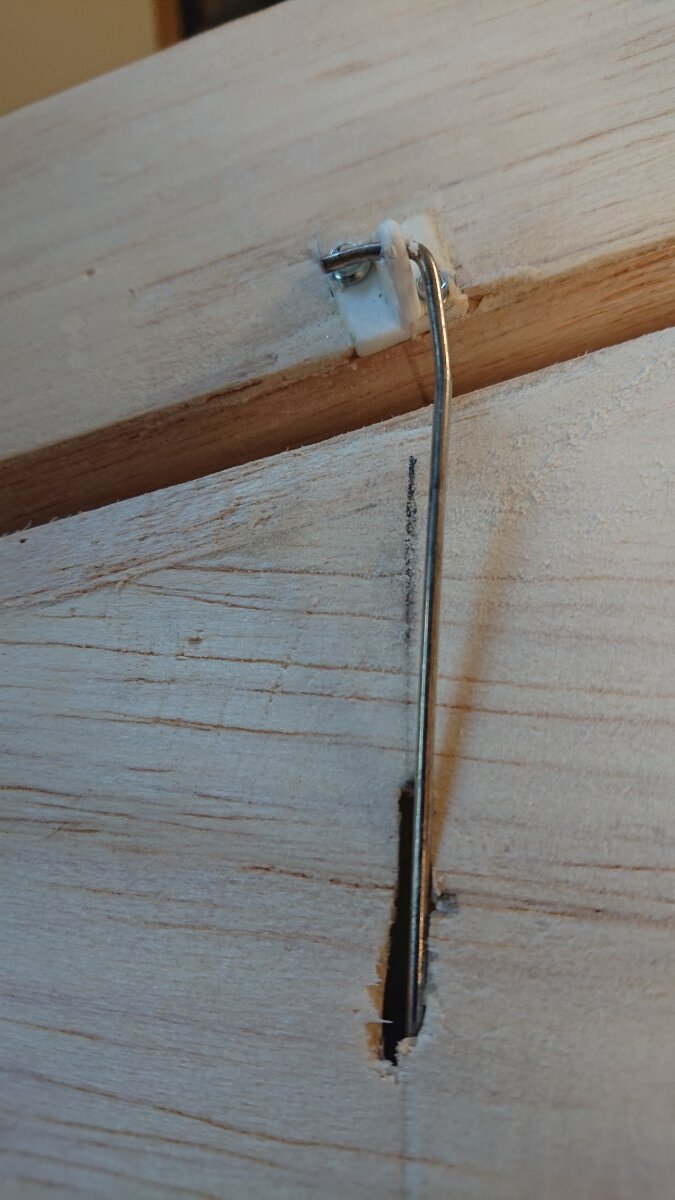
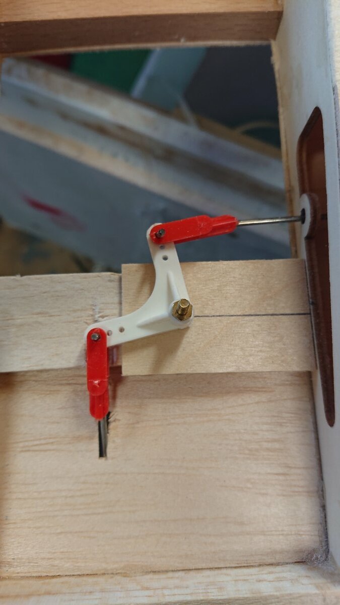
Horns fitted as per plan, the flap uses these micro alloy indoor horns which have been reused. The ailerons use small plastic horns which I had in stock. I didn't like the ones supplied. The aileron horn looks decidely weird at 90 degrees to the te but the linkage comes straight out. Dictated by the position of the hard point. However it seems to work ok.
flap horn
Aileron horn
Servos and servo brackets all went in ok.
And
All linkages terminate with clip locks and clevises at the aileron servos. Soldered washers will secure the pushrods to horns after it has been covered.
Next job is to remove the pushrods and horns, sort out the wing mounting then cover the ailerons and flaps and underside of the wing then permanently glue the hinges in..
More to come..
-
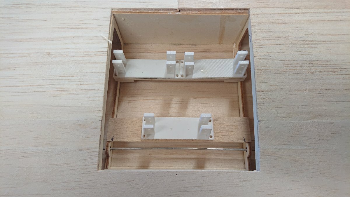
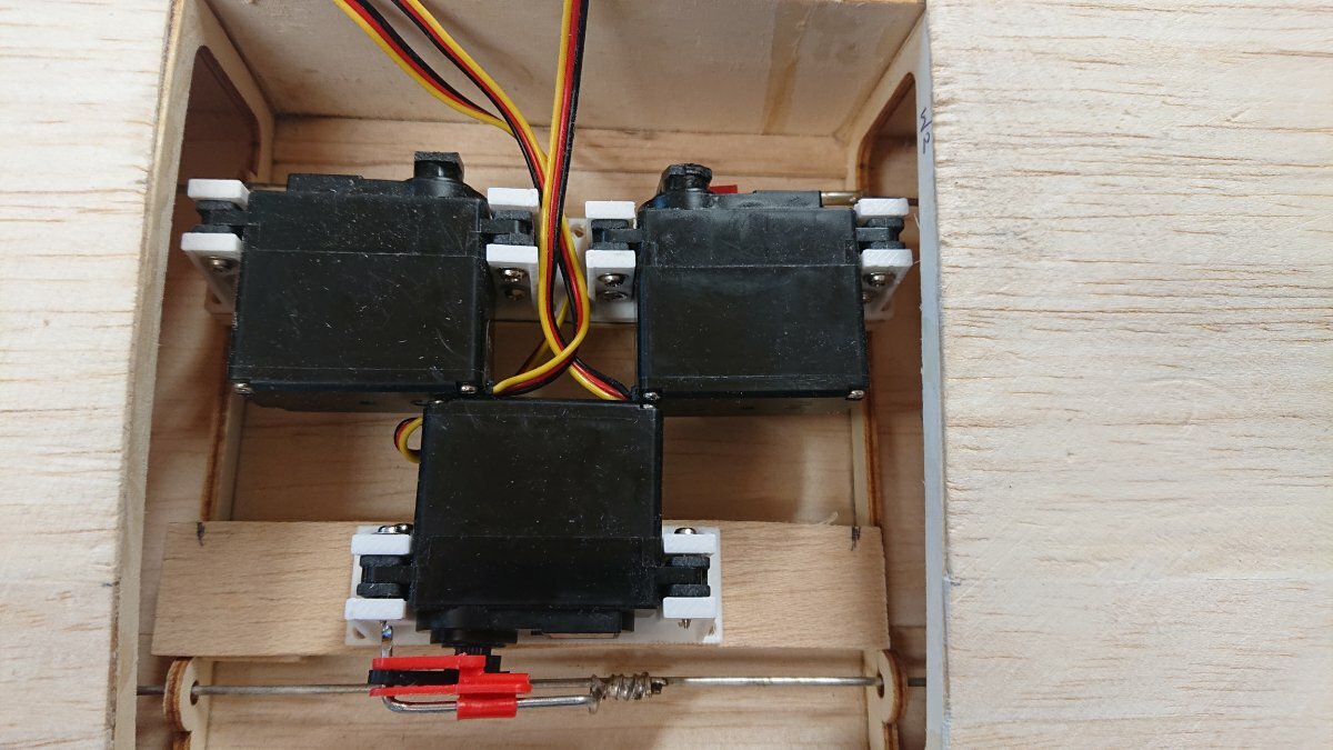
Thanks Piers
The rudder and tailplane servos are mounted under the rear seats. Rudder will be closed loop.
The throttle servo sits between the front seats but is side mounted so only the arm may show. I still need to find a home for the reciever and battery and switch. The reciever may go in the wing. Not really thought it through yet.. 😂


UKCAA Membership 2024
in UKCAA Chat
Posted
Hi all
The UKCAA membership year runs from 1st March for 12 months.
We have introduced a slightly different payment structure for this year.
Basically, as before, subs are £10 per year or now, £20 for 3 years. In addition, new members also benefit from the balance of the first year added as a 'free' year.
The UKCAA website is http://ukcaa.org.uk. Our events are a mixture of Fly-in and a low key contest to UKCAA derived Pick 5 or Pick 7 rules. Have a look on the website for more information and membership application forms. The website also has details of the events that are held and their locations.