


Artto Ilmanen
-
Posts
296 -
Joined
-
Last visited
Content Type
Profiles
Forums
Blogs
Gallery
Calendar
Downloads
Posts posted by Artto Ilmanen
-
-
Thanks Andy.
I hardly use any more sophisticated features beyond some simple mixing such as flap> elevator mix, etc. So from my perspective as long as I have a reliable radio link between th TX and RX I'm pretty much all set. The only exception for what I just said is I'm interested in telemetry and the associated voice announcements. Such as low RX battery alarm etc.
I guess I might be just good with the V4.0 to get the voice announcements.
As a side note, in case you use the voice announcement feature how is your set-up? earphones with wire or have you custom made a speaker set-up on the radio?
-
Thanks Andy,
Ok I see..
Have you by any chance came accross with any review or analysis on benefits and disadvantages in upgrading the T14SG firmware?
I start feeling a bit puzzled wether do the upgrade or not. Mine is V3.0 and so far I have actually been using my T8FG Super TX. Hence, it would be nice to have a better understanding on pros and cons of different firmware versions as it seems the newest firmware may also cause some troubles as you pointed out.
-
2 minutes ago, Paul De Tourtoulon said:
Well, the firmware seems to be v9.0 which is, as far as I know, the latest. On From what I can see, the telemetry language package is the French version. Neither French nor English is my first language but I happen to speak French so I could maybe take this route. On the other hand, then, I should take the French firmware version as well. Which means it’s hard to get support from any of my flying buddies should there be need for that. So, wrapping up I think I will stick with the English software package, for convenience reasons.
In anyways, thanks Paul
-
Good to know - I happen to have also a T8FG Super which I could use for testing, as you suggest.
As a side note, I’m not sure wether the firmware update is mandatory. I just feel that maybe I’m running risks in terms of reliable radio link between the TX and the RX if I do not carry out the update. The current firmware is V3.0 and the latest version is V9.0. For some reason I haven’t seen much discussion on the matter.
-
21 hours ago, Andy Stephenson said:
Artto,
You should be aware if you are upgrading your 14SG later than V4 then any early receiver clones may have trouble with the LBT protocol. If you only have pukka Futaba receivers, then you shouldn't have any issues.
Andy, thanks for the hint
I believe I only have one Frysky clone receiver so I'm not running high risks. Al other receivers genuine Futaba. My current T14Sg firmware is V3.0 and the latest is V9.0 so I feel it is advisable to uopdate the firmware, just to minimize any risks in reliable performance of the TX.
-
22 hours ago, Frank Skilbeck said:
Perkins are now the UK Futaba importer/distributor so you could ask them. I did have look on their website but couldn't see any links to Futaba downloads, but as they have only recently taken over they may not have got those on their website yet.
Thanks Frank,
Very good, I'll contact them
-
Gents,
I want to upgrade the firmware of my 14Sg to the newest (9.0) version:
This is what I found on Futaba USA:
https://futabausa.com/product-suppor...are-downloads/Links on Ripmax site do not work:
http://www.ripmax.com/Futaba_Upgrade.aspx?UGID=T14SG
How can I be assured I download a correct version (European?) Can I download it on Futaba USA?
thanks,
Artto
-
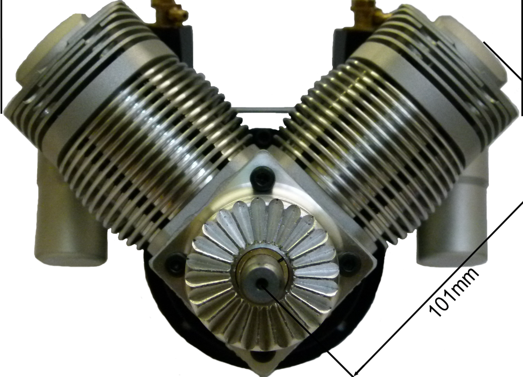
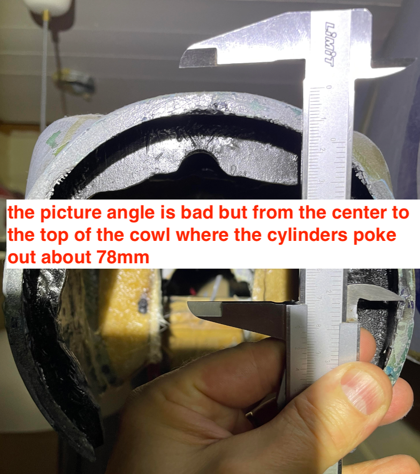
Did you think of mounting the engine upright?
My initial measuring shows the engine (Laser 300V) might fit quite nicely if upright due to the cowling being wider on the top than on the bottom.
I'm thinking to use, maybe, a 300V, to have good performance but I would not like to harm the beautiful distinctive round shape of the Spitfire cowling if this could be avoided somehow. (like mounting the engine upright?). Maybe the engine could be better concealed inside the cowling vs. mounting the engine inverted?
see pictures - most likely some modification of the top section of the fuselage would be needed (a removable section?) would be needed to help with the installation and maintenance of the engine.

-
 1
1
-
-
I can confirm that I have recently got 3 different engines serviced by Jon & Laser engines (2 x 150s and 1 x 300V)
I don't know what this chap on facebook is talking about. Nor do I understand the intention to despise Laser Engines or the great service Laser engines is known about.
-
Great news, Jon
You do not mention about the email - is it now working, again?
-
1 hour ago, Jon - Laser Engines said:
Agreed.
90 degree side mount and its job done with the tank aligned in the position the kit is designed for.
Not recommended. Batteries are not impressed by heat, oil and vibration so tuck them up behind the firewall out of harms way. If additional ballast it needed (it will be) take another engine mount and install it under the engine. You can them mount the lead on the 2nd engine mount and get it a long way forward for maximum effect.
Thanks, Jon. I just want to follow your instructions as rigurously as possible. 🙂 And as such, some modification, although pretty minor, is needed (lower the tank) to get the tank height as instructed by you. It's hard to know when and to what extent one can deviate from the official instructions.
Thanks for the hint concerning the rx batteries. While I have never had any issues in the past when having them mounted inside the cowling, maybe I have just been lucky!
-
18 hours ago, Ron Gray said:
I haven’t flown the Bearcat for a while, it is a bit overpowered with the 240v but I needed the nose weight anyway!
Thanks Ron,
Yes, these models seem to be tail heavy easily. I try to avoid use of unnecessary ballast by mounting the rx batteries inside the cowling. We'll see.
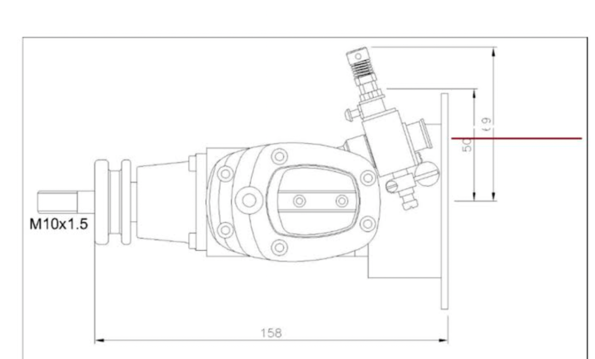
Anyways, I think I'll go for the side mount route with the 150. After second inspection I noticed that I don't need any more cut out of the wing at all as there is already some by the factory. What comes to the tank height vs carburetor I found a picture by Jon on the other thread so I believe it's clear now. The read line in the picture is "in the middle of the carb".

-
39 minutes ago, Ron Gray said:
If you line the tank cut out with ply or lite ply then you won’t weaken the wing, my ESM Hurricane and Mustang have both been altered like that with no ill effect.
Thanks Ron. This makes sense.
As a side note - have you been flying your Bearcat with the 240V? What are your experiences?
I had been thinking of a 240V for my Focke but having spoken with Jon the 150 seems to be a better choice for the Focke
-
Thanks gents,
I do not mind modifying the model if needed. The only thing I’m thinking is the wing - will it become weaker if I carve it 5-7mm to make room for the tank.
If I Interprete Jon’s instructions right the second picture is how the tank should be in line with the carburetor?
-
Hi Jon & gents,
I'm installing a Laser 150 on my ESM Focke Wulf
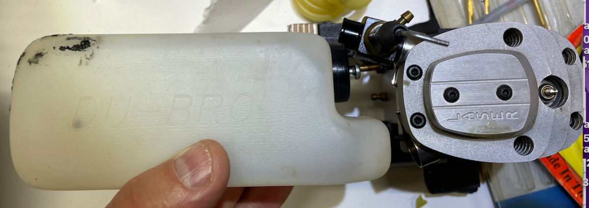
If side mounted the top of the tank seems to be about 7-8 mm higher than the centre for the carb: see picture if no mods done
If I understand your instructions correctly the top of the tank should be in line with the the spray bar? See the other picture
Anyways, if I lower the tank as instructed I need to either find a tank which is not more than 50mm of height, which is the space available until the wing comes in way (the 12 fl oz Dubro in the picture is 57mm). Or I can modify the wing to have some more space for the tank.
Anyways, the right size & shape tank might be the easiest solution. I came across this, Sullivan Flexi tank, any experiences? According to what the manufacturer says "they can be reshaped with a heat gun if desired." -> maybe this could help with reshaping the tank to fit into the 50mm space available.
https://sullivanproducts.com/product/rectangular-flextank/
As a side note, for some reason I haven't been able to find a tank of 50mm of height as max (Sullivan, Dubro, Kavan)
Another route to ensure the tank height is correct is I could, of course, rotate the engine somewhat so the cylinder would be pointing to 10 o'clock or something to help with respect to the tank height vs the carb. See picture. Not sure how elegant this is, though..
Any thoughts or recommendations?
Artto
-
3 hours ago, Jon - Laser Engines said:
This is extremely common and not a big issue. I would say that 6 out of 10 engines i service are like this and the deformation i mentioned was relatively insignificant. I only changed them so it didnt get worse. Some engines over the years have had the pads melt to the point where they lock up the piston, but i think i have only seen about 4 or 5 examples of that in the whole time i have been here. Often the heat that melts the pads is partly due to friction on the cylinder wall. PTFE is low friction, but over time it has an effect.
But, had i not mentioned the pads and just swapped them like i normally do (and did on one of your 150's) you would not be worried about heat. My idle comment of 'yea it might have run a bit hot so double check your baffles' has been conflated into a Chernobyl Reactor 4 situation when it was nowhere near that bad. If you fit a temperature sensor you will be even more worried about heat than you are now. I cannot give a temperature limit figure, so knowing how hot your engine is will be not be of any use as you have no value to compare it to. Quite often engines are at the hottest on the ground while having the last rpm wrung out of them. This is why i vague up my rpm numbers as i know a number of customers who will not be satisfied to see 8400rpm if i said it should do 8500 and will wring the neck of the thing trying to get the extra 100 revs.
My point is too much information can be extremely detrimental and very distracting. While you are worrying about your 'missing' 100rpm or are focused on your tx beeping at you about engine temperature you arent giving your full attention to flying the model. Without a recommended temperature limit for the engine temperature sensing is basically a curiosity and of no real value anyway so you might as well just remove the distraction.
Why dont we provide temperature data? The reason is we simply do not know what the limits are. I can make a very well educated guess, but we do not have the resource to test it in a meaningful way. To do it properly and provide real data you would need to endurance test countless engines at different temperatures and observe the results after hundreds of hours of running just like they do will full size engines in aircraft, cars etc. The time involved, the facilities required, and variation in model fuel/oil quality used also makes the job completely impossible.
So i am going to tell you the exact same thing i have been telling you the last 10 years. Install it right, tune it up and just fly it. Dont worry yourself into an early grave, just fly it.
Hi Jon,
Thank you for your advice - I believe what you wrote is good, not only for me but also for many other Laser enthusiasts as I happenen to be not the only one thinking of measuring Laser engine temperatures.
I see - so the PTFE piston pads deforming is, like you write, pretty common. I thought my case more like an unusual case but I was wrong. Anyways, for that reason I may have overcomplicated things again. Sorry for that. I do want to follow your advice as you, as the manufacturer representative, know best the right use of the engines. This being said, this cooling / ducting / baffling theme and what are the associated good working practices can sometimes be "black magic". Hence the use of technology to prove things are fine can feel alluring. But anyways, I content with your help, Jon.
-
19 minutes ago, Jon - Laser Engines said:
As always i recommend you start it, tune it, and fly it. Forget all the baggage, just fly it.
Jon,
I see your point. This being said, as you pointed out in another conversation my the PTFE piston pads of my 300V had deformed somewhat indicating the engine had run a tad hot (while not overheated). The model on which the engine sits has baffling helping with cooling the engine. Therefore I feel tempted to try, maybe temporarily, the temperature sensors to tell me if my cooling ducting is working or if the cooling arrangement still needs some changes.
-
9 hours ago, Frank Skilbeck said:
Artto have a look at the Powerbox PBS-T250, but you'd need the programming lead to change the operation to Futaba.
Thanks Frank,
Yes, with Futaba you need to purchase the programming lead which is 29€. But then again, this is one-off cost that can potentially be used for other purposes, too?
Anyways, so far this seems to be maybe the best alternative - at 49€ you get the temperature unit with 2 temperature probes. And the unit can handle up to 5 temperature probes (additional probes can be purchased separately for 9,8€ unit price which is quite reasonable). Anyways, much more attractive a solution compared to genuine Futaba which is 100€ for just one temperature probe.
One thing that I do not like is the way the manufacturer suggest to mount the temperature probe:
extract from the manual (https://www.powerbox-systems.com/uploads/tx_pbsdocuments/6621_BA_PBS-T-250_EN.pdf):
"..The temperature sensors are designed to be attached to the cylinder head using a screw-lug. Drill a 3.5 mm Ø hole in one of the cooling fins, then fix the temperature sensor in place securely using a suitable self-tapping screw or M4 machine screw. A small quantity of heat-conductive paste under the sensor improves the temperature measurement."
-> in no way I'm going to butcher my beautiful Laser engines! There must be another way to do this. A picture of the temperature probe:
https://www.powerbox-systems.com/produkte/sensoren/temperaturfuehler.html
-
3 minutes ago, Dickw said:
SM Modelbau in Germany make sensors that are compatible with Futaba, but are mainly aimed at electric models. To get a temperature sensor you would have to use their UniLog 2 with their add on temperature sensor. Not a cheap solution, but different.
https://www.sm-modellbau.de/UniLog-2-und-Zubehoer scroll down the page for their 300 degree temperature sensor
I use quite a lot of their gear and it all works well for me.
Dick
Thanks Dick!
I will have a look on these
-
Thanks Dick,
You are most likely referring to this:
https://file.espritmodel.com/documents/pdf/jeti-mt300.pdf
extract from the manual:
"..Before tightening moisten the silicon tube with alcohol or white spirit in order to improve its sliding ability on the cables. Put the measuring object, for instance an engine cylinder, through the loop and tighten the loop strongly by means of the silicon tube in order to obtain a tight contact between the loop and the measuring object (for instance with cooling fins of an engine cylinder). After evaporation of the alcohol the silicon tube will firmly hold the loop tight. In order not to damage the sensor the dia. of the loop should not be smaller than 20 mm."
Maybe this setup could work. I'm not sure if there are any Futaba FASStest compatible sensors other than genuine Futaba, though. But the principle of mounting the sensor can most likely be similar no matter what make sensor in question.
-
5 minutes ago, Paul De Tourtoulon said:
Blocked futaba lien,,,
Sorry Paul,
I'm not sure if I'm following you..?
-
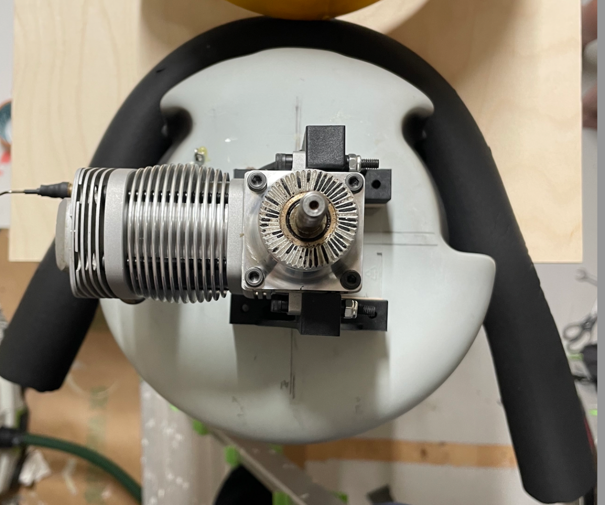
Jon / gents,
I would like to have measure engine temperature on my Lasers. Maybe not as a permanent solution but more like testing that the baffling is doing its job as expected and so on, for peace of mind. Anyways, do you gents have any experience on telemetry sensors such as this one or similar:
https://futabausa.com/product/sbs-01t/
It may be difficult to keep the wire sensor close to the cylinder head, though. Maybe the optimal solution would be to have a tab on the copper glow plug washer to which you could attach a temperature sensor. And thus get a more reliable reading. Unfortunately, I haven't seen any sensor like like that on the market so far.
Any thoughts or first hand experience on some set-up to measure engine temperature?
-
I used the traditional UI succesfully yesterday - a phone call to Laser Engines 🤣
-
Hi Jon,
I hope you have a nice holiday - may I ask you when you are back at work? I just hope to get my 300v back from your excellent maintenance 🙂 btw, I just got a notification that my 150s have arrived at local post office.


14SG software update - where to download?
in Futaba
Posted
Thanks Andy
Ok, I sent email to JPerkins on where to download the firmware updates. It may be difficult to find past releases, such as V4.0, though: Futaba USA lists only the V9.0 - so let's see. Ripmax used to list all firmware update versions but the links work no more.