


Mike Chantler
-
Posts
299 -
Joined
-
Last visited
Content Type
Profiles
Forums
Blogs
Gallery
Calendar
Downloads
Posts posted by Mike Chantler
-
-
16 hours ago, Simon Chaddock said:
ensuring each plank is as accurately preformed as possible to avoid stressing the half shell and ending up with a twist.
Although rather tedious it does mean the new nose will weigh exactly the same as the original/
Have always wondered - do you chamfer the edges of the planks to fit. (Its looks as if you have yours nicely butting)
And if so, what's the best way with delicate 3mm foam?
-
Nice project, interesting! looking forward to seeing how it works out at this size 🙂
-
 1
1
-
-
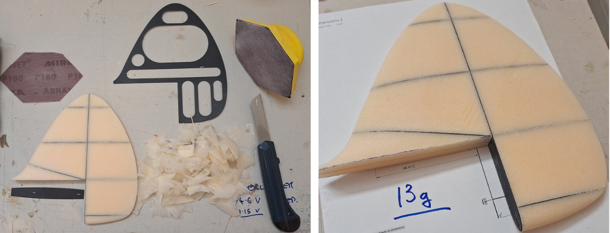
The 3d printed tailplane frame covered in 1/16th balsa was surprisingly heavy at 50g or so. So decided to experiment with using a 3D printed frame to help carve a XPS fin:

Quite pleased at weight and how quick it was to do.
We'll see how much I add with the glass etc.
-
1
-
-
So I have still been bashing on with various ways of using 3D printing to help in building the tail. Have only had a little time so it's been slow, and I've probably discovered everything you shouldn't do when 3D printing.
Quite a few attempts at different ideas:
Various things I wouldn't try again!
-
Wow, that's an impressive build, missed that one! Quite a challenge!
Not sure I would have so much patience or skill 🙄 Very interesting methods - may borrow some of these 🙂
Thank you
-
On 27/02/2024 at 17:35, Simon Chaddock said:
If you want to build an RC model airliner printed fuselage formers represents a really economic way to make lots of identical fuselage formers.
The clever bit is how to use them!
Simon,
Looks great 🙂 and tres light 🙂
Is it planked with 3mm foam? Can you let us know what sort of size are the formers are and what you use for a jig? (or is there a build thread?)
Thanks
Mike
-
11 minutes ago, MattyB said:
Isn't printing the tail likely to put a lot of weight back there that will require extra noseweight to balance? Your skills are undeniable, but I'm not sure in this case a printed tail will be the best idea... What is the projected weight?
i agree - I think I should just bite the bullet and go for all foam tail feathers, the alternative would be flat balsa which for a spit would be soooo much easier. And my 3D skills are still very questionable as I am so slow!! Next WW2 project with have wings and tail feathers that I can hot wire!
-
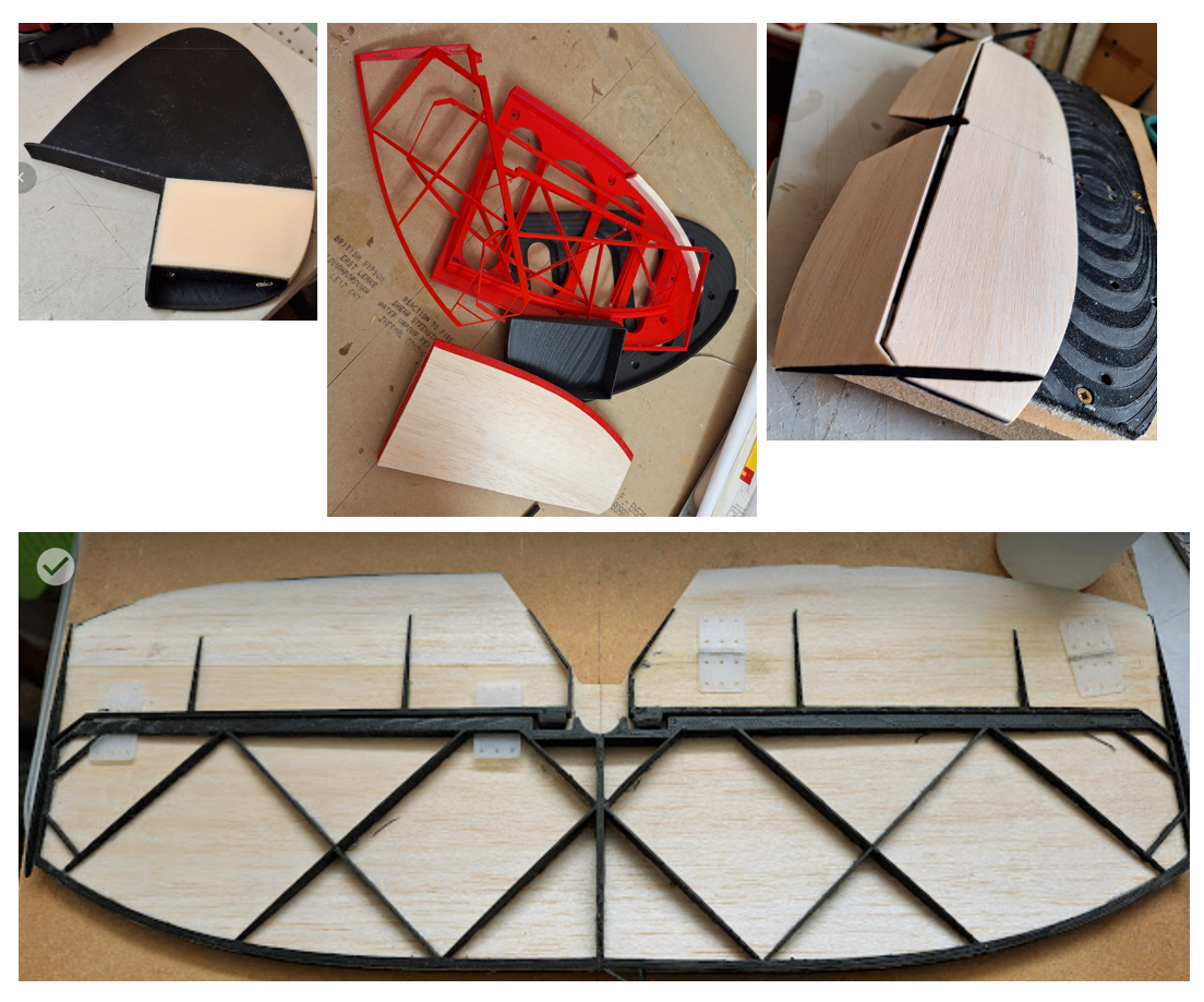
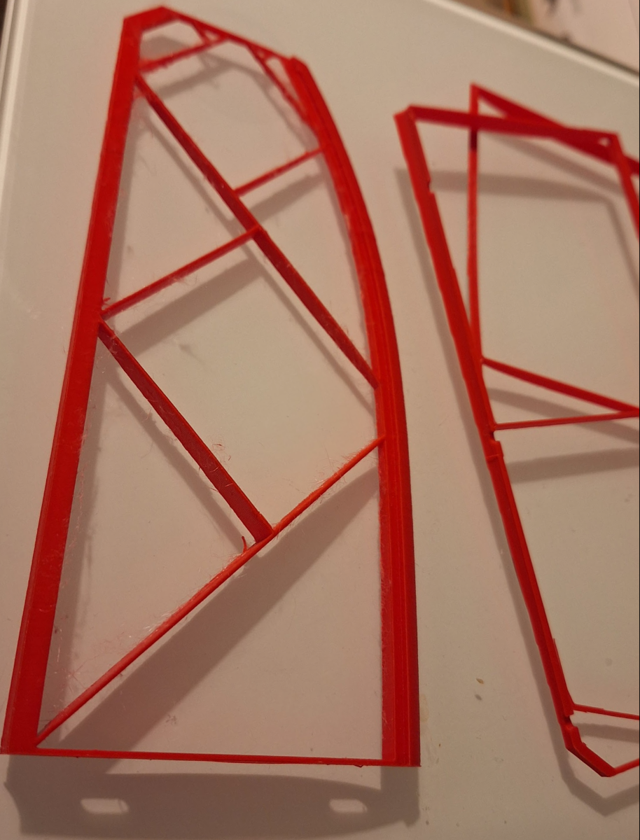
Having got the model I was then tempted to see if I could 3D print a framework for the tailplane:
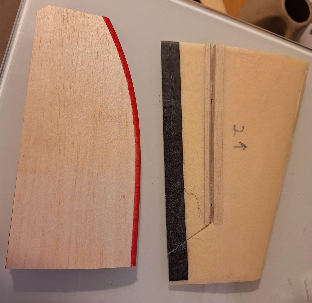
First attempt at splitting framework horizontally for printing didn't really work, so changed to 45 degree cross members (to prevent need for supports) and printed whole thing vertically. Then CAed 1/16th balsa skins on each side and have easy to produce tailplane half at circa 16g.
In comparison with a hot-wired foam/carbon/glass version it's at least twice the weight and has yet to be glassed(!) However, I'm not sure i have the patience to carve/sand the foam version to the curvy shape required for a spit. If I had a laser cutter I might prefer trying a fully balsa built up structure.
Current plan is to go to the pub and rest my head!
-
I went down a real rabbit hole with the 3D modelling.
But I now have a full solid model of the tail section and feathers - took ages - there's not a single curvature or even bi-linear surface anywhere on a spitfire 😞
So all of the lofting etc takes ages. Result is a quite scale body with NACA 0010 fin and tailplane sections:
Would I do it again --- hmmmm... maybe not! But one of my goals was to come up the learning curve in the modeller.
-
2
-
-
Looking really nice 🙂
-
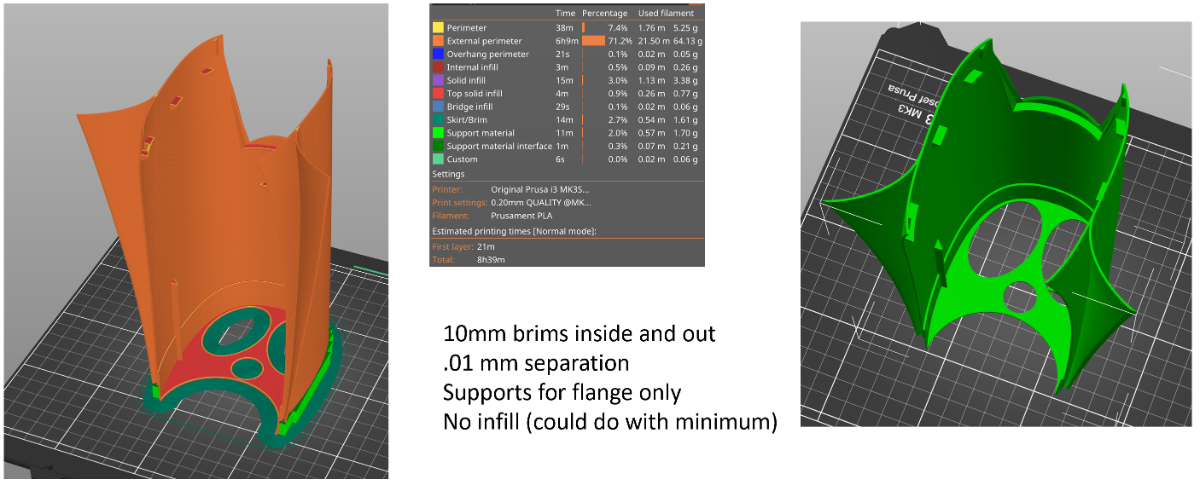
Some print settings while I remember:
-
1
-
-
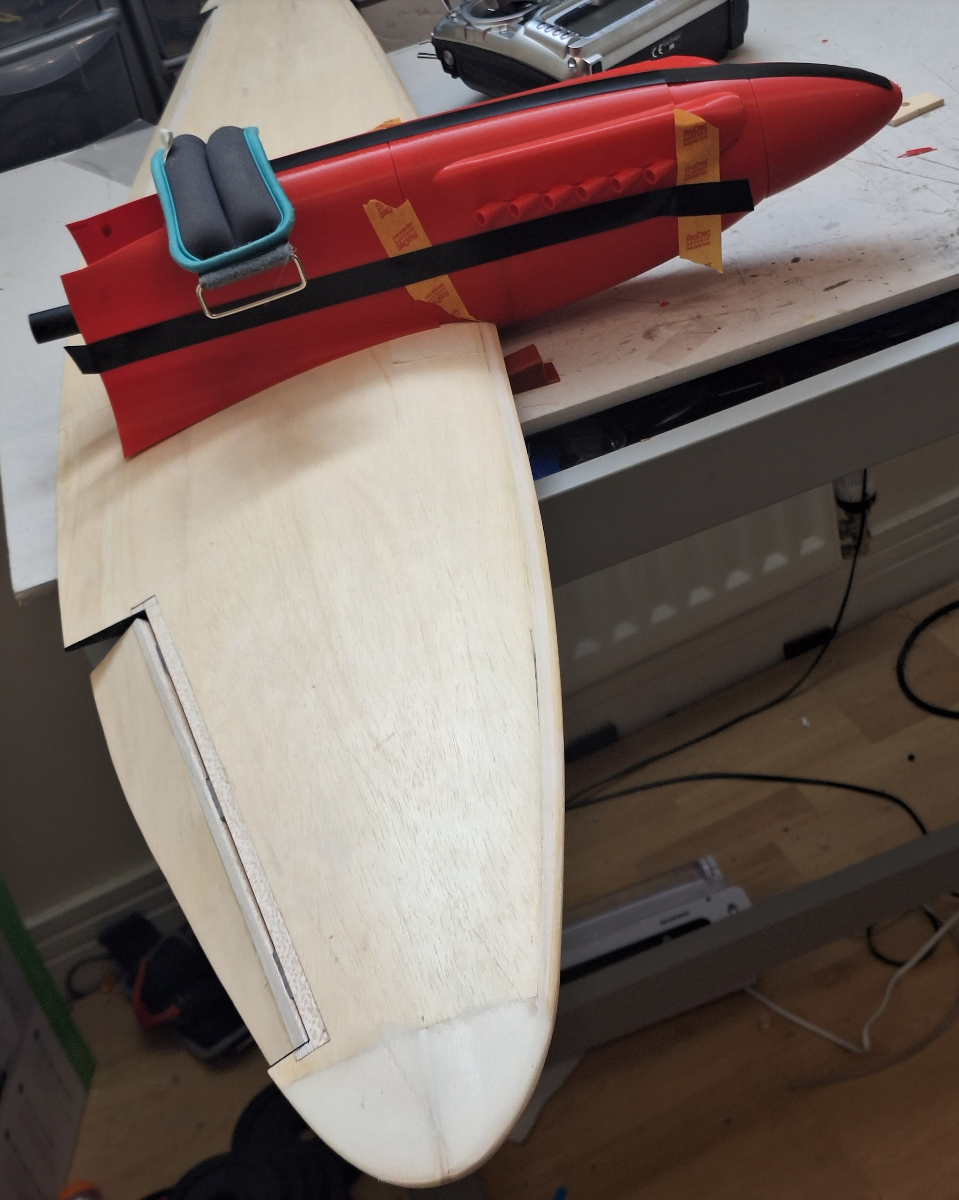
One problem I had was that while the foam cores were exactly the right size, the veneered wings are too thick - by errrr... 2 x .8mm veneer. duh! 😮 😞🙄
I was convinced the vac bag was going to crush the cores a bit and in a traditional build this extra thickness would not matter as you'd just build the fuselage on top of the thicker wing. However, the pla is really difficult to sand, so I added a skin in the 3D design and moved the wing up by .8mm. This is fine for the body but means that the fairings of the next section (behind the wing) definitely will not fit and I'm not sure I can be bothered relofting it as its edge rails are both time-consuming compound curves and the loft itself is a bit problematic. So I think I'll maybe print the next section without fairings and then add them traditionally.
-
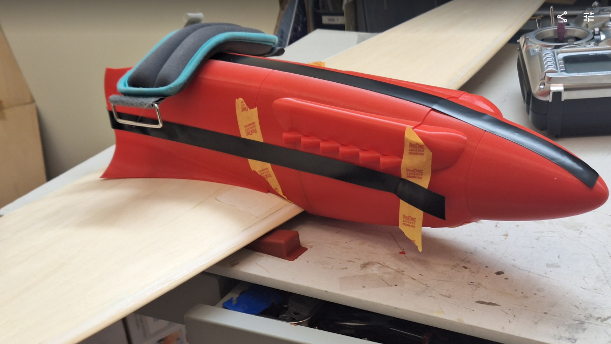
Still going - but very slowly! Got chance to print off front two sections (first section in 2 parts).
Thinking it is beginning to resemble a griffon engine spit 🙂
Designing the second (blue) section took me several goes due to the cockpit and additional flanges for the bulkhead and servo tray.
-
4
-
-
Nice 🙂
-
On 13/09/2023 at 16:36, Nick Somerville said:
Stab and elevators now completed. The shroud at the t/e of the stab is let in G10. The elevators are about 40grams heavier than the stab despite every effort to sand as much of the 1/32 ply core away. I will fabricate the trim tabs after covering the tailplane. Fin and rudder next.
Lovely build. Curious as to what the G10 is?
-
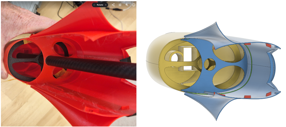
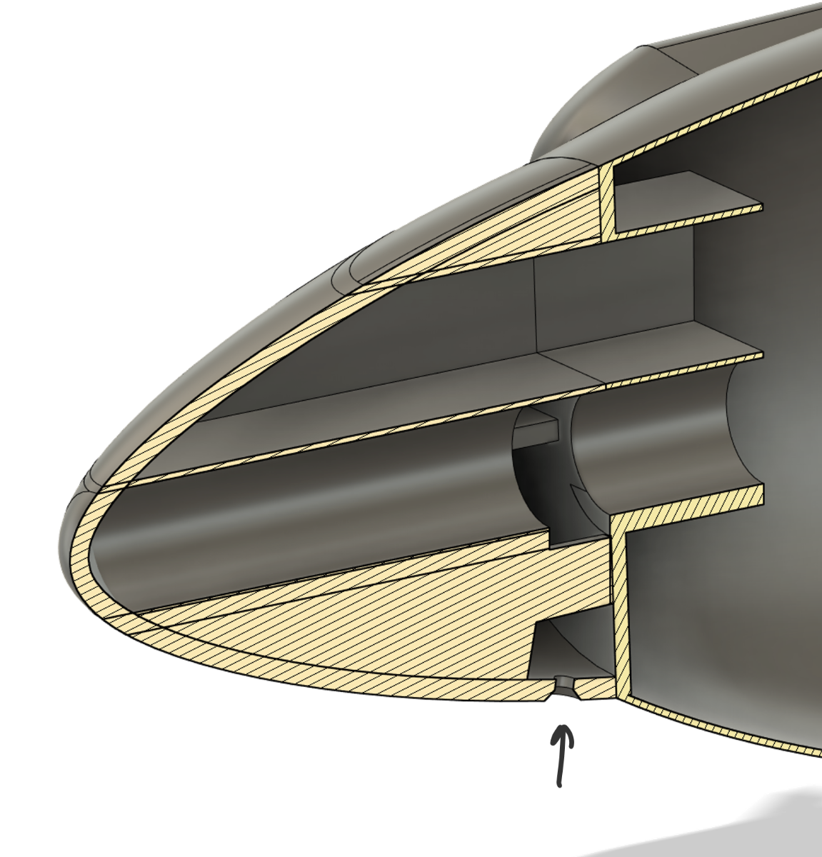
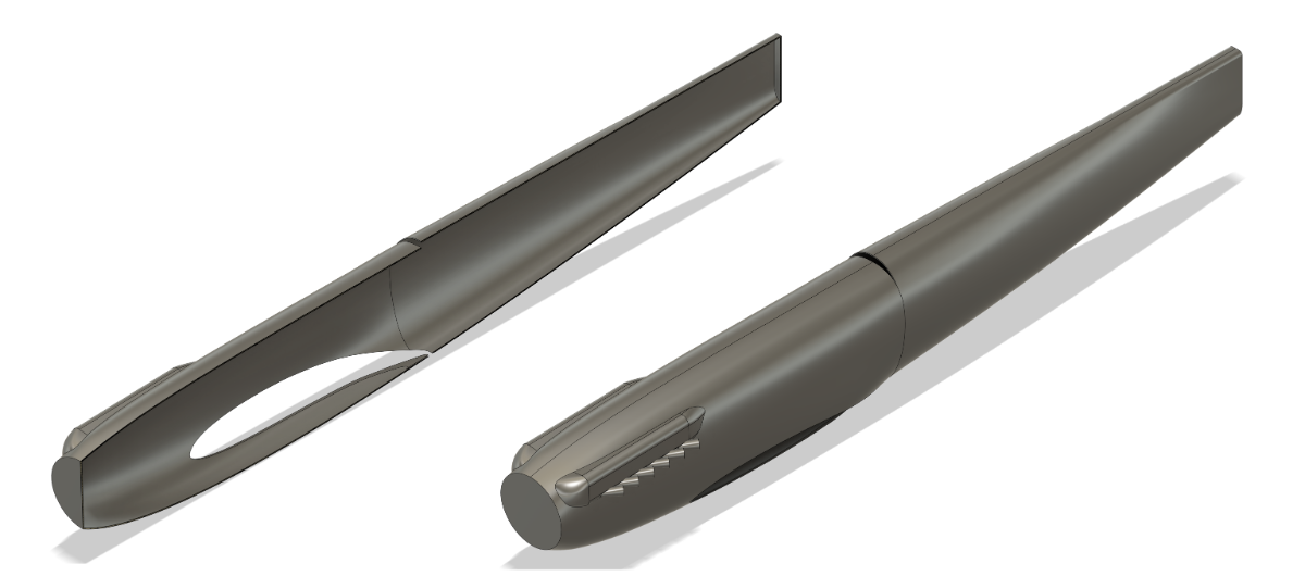
Thanks - yes idea is that spinner slides off ballast tube to give access to battery and for loading slugs. Will simply have single countersunk screw to hold in place:
Needs bit on front of body to screw into(!)
1mm PLA cross shaped former is just to make sure ballast tube aligns while real former positioned and glued. Will either be liteply or 6mm B&Q foam/carbon sandwich to securely connect front wing dowel to ballast tube.
Similar at rear of wing to take stresses of ballast tube vs wing. Time will tell 🙂
-
Rear and centre sections may still be bread and butter xps depending on weight of 3d prints strong enough to take slope abuse.
Above is from devfoam wing, which after a bit of hassle, I found reasonably easy to use 🙂
-
1
-
-
So after a lot of procrastination I'm finally getting somewhere with my 3d design - still very slow!
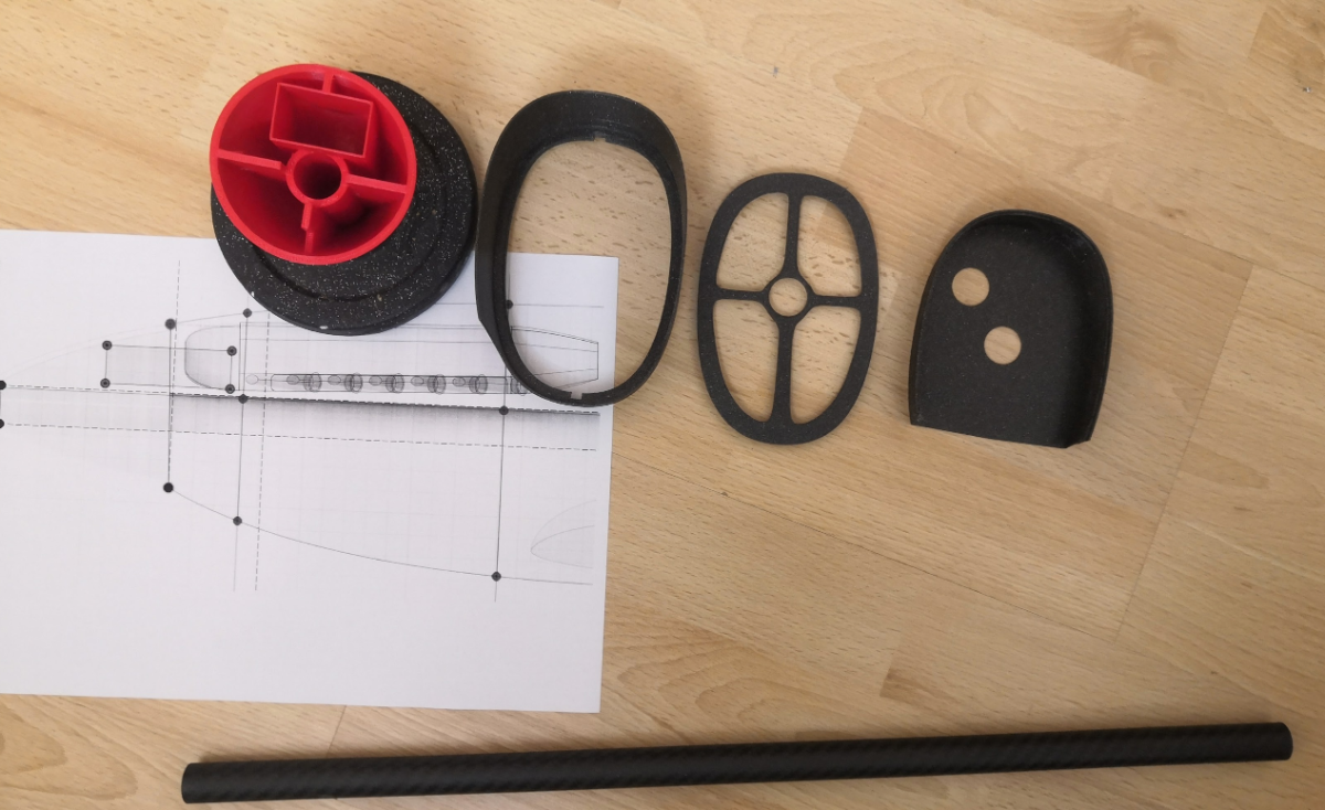
Spinner in 3mm with holes for battery and carbon reinforcement/ballast tube.
Printed off spinner (red) and the rear of section 1 + front of section 2 to see if my flanges etc work:
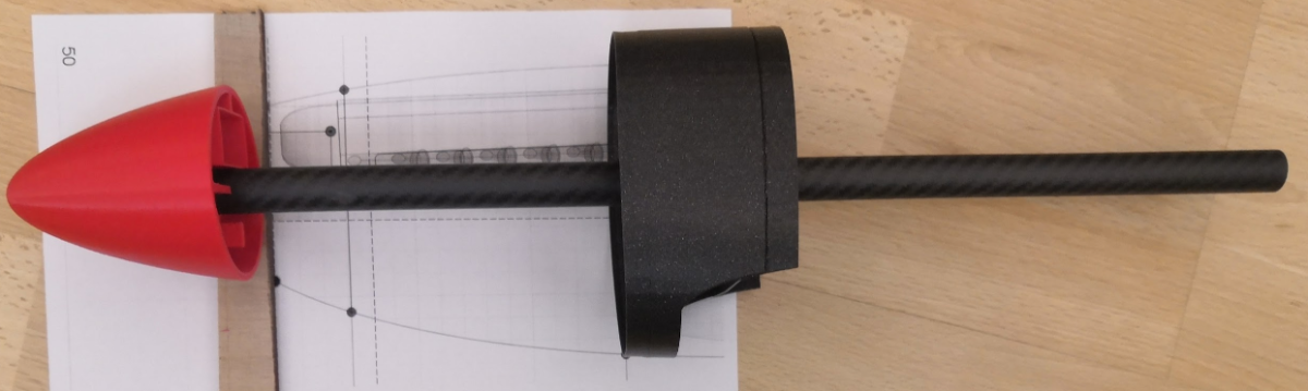
Hand assembled as sanity check:
Ballast tube is 18mm x 500 and spinner and exhausts have 2 degrees 'down thrust' otherwise it looks weird 🙂
-
I built an F86 from an old Ron Collins plan. I was a bit shocked by the price of the balsa so I replaced it all one-for-one with XPS foam sheet and sections, plus some 6mm carbon/foam sandwich in place of liteply formers. Took me quite a while to learn how to use and finish it as a) it dings really easily during construction, and some of the foam glues stay really rubbery which means they don't sand. Next time will cover in brown paper before glassing, and keep the glue very thin and use the stuff that dries hard.
-
6
-
-
Thanks Simon, enjoying your log and I especially like the wing construction above.
I'm building a 46" PSS spit, target 1kg plus so - so suspect I have a lot more weight that I can afford (and need) in the structure than you.
Front half of fuselage is 1mm PLA skin with some foam/carbon bulkheads to absorb hill landings in gales. Rear likely XPS with some PLA bits (depends on overall weight!).
And it has an 18mm carbon ballast tube running 500mm from the spinner. I like that glue you recommended so will use this for foam-to-foam and foam to carbon - thanks.
Suspect your weight will be a fraction of mine(!) and I don't even have a motor lol
Designing with Fusion 360, which I have to say is taking me quite a while to learn!
-
Simon, nice build as always 🙂
Am curious, as I'm doing a mixed carbon/foam/pla build myself, what do you use to glue pla and lwpla to the foam? Do you use the foam glue you mentioned earlier in the thread? And is it CA for pla to pla?
-
I usually cut the plan into big bits, wing, fuselage etc, and then cover with mylar or some other clear plastic. But a second copy always helps as some how or ever, I always end up partially destroying the original.
-
Fuselage is ordinary PLA except for carbon ballast tube.
Wing is 75g laminating film on hotwired EPS (as I can't get EPP).
You have to be carefull with the temperature of the iron!!
Spars are double, full-length, 6mm carbon tube (top and bottom).
Has hardwood LE and balsa sub TE with correx ailerons. Tips have ply end-caps.
Think I'd change TE for thin hardwood, and swap ailerons for hard balsa.
Plan and Fusion 360 model on Tim's GitHub pages (url at start I think).
My Fusion 360 mods are VERY untidy - would send only via PM as they are a bit embarrassing!!
-
2
-
-
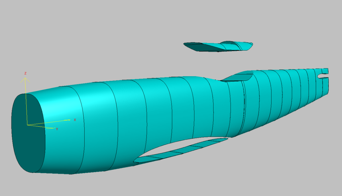
So having decided to make the fus largely out of foam I've now done a 180 degree about-face, and think I will experiment with 3d print using a 1mm shell and use the carbon ballast tube and some internal carbon reinforcement, in a similar manner to the 60" plank.
Just getting a shell for the body took me a while due to my incompetence with the 3d modeller.
This now needs cut up and flanged into printer-sized bits, and support added for the ballast tube..
-
1
-


An RC Depron Douglas X3 Stiletto
in Own Design Project Blogs
Posted
I especially like the idea of the fresh 60 grit - and think I'll also try this on some XPS shaping that i am doing at the moment.