


John Stainforth
-
Posts
728 -
Joined
-
Last visited
-
Days Won
2
Content Type
Profiles
Forums
Blogs
Gallery
Calendar
Downloads
Posts posted by John Stainforth
-
-
9 hours ago, Robert Cracknell said:
All this is well and good and beyond me......but, can anyone explain why I cannot get a slice of 'Toastie' bread to fit in my toaster without having to trim one side?
That's explained by Relativity. The size of the bread is too big, relative to the toaster.
-
 2
2
-
-
12 hours ago, Jon - Laser Engines said:
If you need oil to fill the gaps then throw it away, its ruined 😄
This subject of castor is so worn it could probably do with some castor itself, to gum it up before being thrown away!
-
1
-
 2
2
-
-
On 07/06/2022 at 09:20, Danny Fenton said:
Hi Eric, this undercarriage is made up of three sections of 6mm piano wire soldered into a triangular base, therefore no spring, it is extremely rigid. I would prefer the undercarriage to give or even collapse on a hard landing, If I put this down hard the structure will feel the pain, probably struts and wing mounts.
Its frustrating because I have sprayed Klass Kote silver on my last model, the hawker Fury, and it went on a dream. But you are right metallics can be a mare. Get the pressure and viscosity slightly out and it goes on too dry, which is what has happened here. Usually 1:1:1 is spot on...... several modellers say the same. I have a feeling I instinctively reached for celly thinner and not the official Klass Kote reducer and that's the root of my problem.
I have a Seagull Chipmunk to "re-colour" so we will see.
Cheers
Danny
Beautiful build. If you put celly thinner in the Klass Kote, I am surprised it worked at all!
-
One thing to be careful about, if you go back to 35 MHz, is to remember to pull the TX aerial out. (How do I know?!)
-
I found foam rollers work best for applying the first coat of resin, rather than credit cards, supplemented with foam wedges for jabbing resin into corners etc. It is not necessary to seal the wood first, but it should be sanded really smooth and imperfections filled with filler before applying the glass. The first coat of resin, rolled through the glass, should be just enough to stick the fibreglass down to the wood. Most people apply a second or "flow" coat of resin (rather than a filler) and this should just fill the weave, but no more. I found a one-inch brush most satisfactory for this second coat of epoxy resin. (I suspect that quite a lot of the variations in technique are a matter of personal taste.) The really heavy lifting is in the sanding after each coat has dried. Then the primer for the paint is applied - best to use a compatible epoxy primer rather than a car primer; then more sanding; then the paint coat(s).
-
On 24/03/2022 at 09:42, MattyB said:
Registration may be straightforward, but don't forget Remote ID is now enshrined in US law with implementation looming in the medium term - dates and further details are on the FAA site...
-
September 16, 2022:
- Drone manufacturers must comply with the final rule's requirements for them.
-
September 16, 2023:
- All drone pilots must meet the operating requirements of part 89. For most operators this will mean flying a Standard Remote ID Drone, equipping with a broadcast module, or flying at a FRIA.
I confess that I am not familiar with the fine details of the final rules that have not yet been implemented, but this does not sound too onerous, since most current AMA model flying sites will be classified as FRIAs.
-
September 16, 2022:
-
We live in difficult times and the overall intention of this registration is benign and not a significant cost. I think it helps to increase the respectability of our hobby.
BTW, the registration process with the FAA in America is not more onerous - it is more or less identical. (As I predicted, we have more or less copied the American process, with a lag of a few years. This not surprising: most rules around aviation are pretty similar in the whole western world.) One difference: registration was adopted by modellers there with very little fuss, although there was a lot of discussion and angst before it came into law, because at one time it looked as though the constraints on aeromodelling were going to be much greater. Overall, the US government is rather in favour of aeromodelling, because they see it as a potential recruitment vehicle for the aviation industry and the Air Force. (Remember, the likes of Neil Armstrong, and Rutan started as aeromodellers.).
-
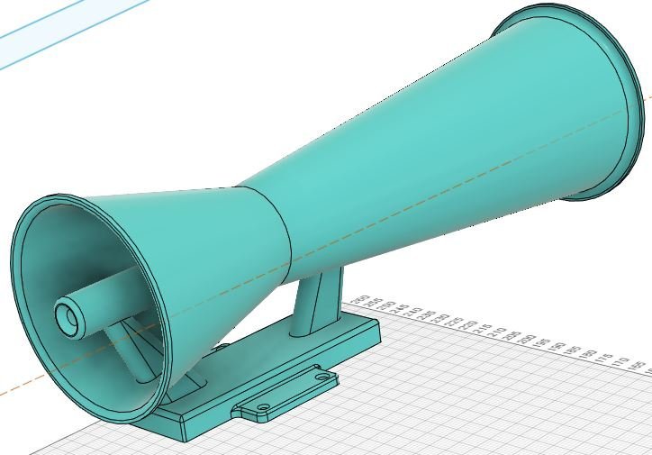
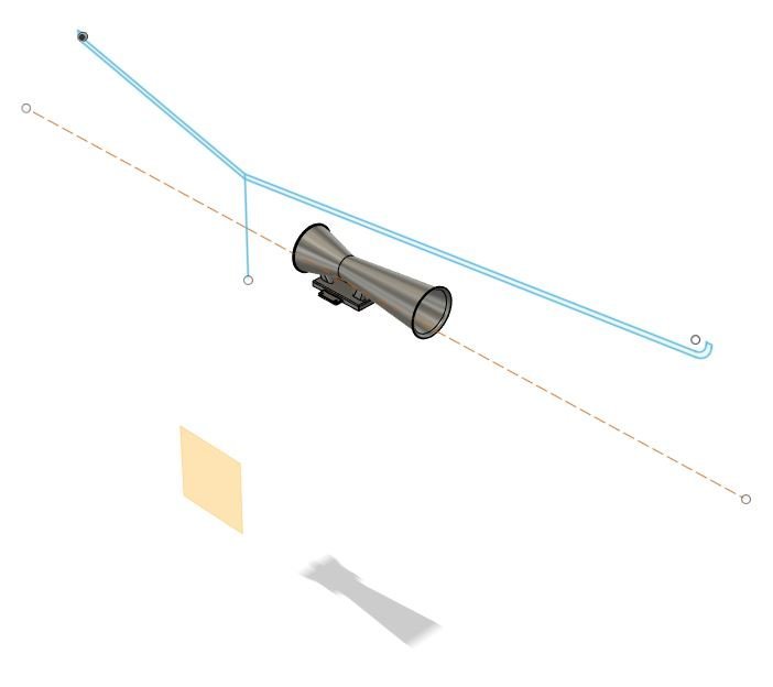
10 hours ago, Danny Fenton said:
Revolve is very handy to create cylindrical objects about an axis

I find the biggest problem is when you return after a week and have to re-learn ?
Cheers
Danny
With 3D CAD, I've found what works best for me is to record everything I do as I go along. This way I have gradually built up my own manual of the best ways of doing each kind of task.
-
1
-
-
7 hours ago, Ron Gray said:
@John Stainforththe hinge is formed by extending the covering film over the hinge surfaces, i.e. one continuous piece of covering film for the underside of the wing and ailerons, ditto the top surface. The hinge is not formed from a separate piece of film.
Regarding how long they last, I can’t answer that as none of mine have yet to fail! How strong are they, well I’ve had a mishap with one of my models in which the wing was torn off, the aileron covering film hinge remained intact. Try pulling a piece of covering film apart with your fingers, it’s quite strong!
Thanks for the explanation. Most plastics are great in tension, but not so good when bent back and forth repetitively. That's the way I destroy my old bank cards. Even mylar hinges eventually crack up as a result of this bending. I imagine the film method is only really OK for small models, but I could well be wrong.
-
On 10/03/2022 at 21:35, john stones 1 - Moderator said:
Agreed, and they cost next to nothing, are very neat and maintainence free, they wont go brittle with age nor the glue deteriorate, and they don't need pinning.
Please can someone enlighten me as to what is meant by a "film" hinge. A film is just a thin layer. But what are the recommended materials (type of plastic?) and thicknesses? Surely these are crucial factors as to how well these work as hinges and how long they might last?
-
Fracking won't do it.
The potential for shale gas in the UK has been greatly exaggerated.
-
I hope I don't understand.
-
5 hours ago, Phil Taylor said:
Is anyone out there running their Saito R3 120 on anything less than the recommended 20% oil content?
I am using Optimax 20 Super SLV which works fine - but the amount of unburnt oil coming out the exhaust is incredible!
I run Laser engines (100's, 150 and 155's) which all run on the Laser 5 which is great with very little mess without any issues (I do like Lasers!).
I don't want to ruin my lovely new Christmas present - but I could do without the mess. I ran a whole gallon of fuel through and the Workmate stand I used looked like I had poured a litre of cooking oil over it!
Any comments/experiences would be appreciated.
Cheers Phil
Have you fully tuned the engine, i.e., both high speed and low speed needles? Generally, the low-speed settings have to be leaned out a very long way from the factory settings.
-
1
-
-
I apologise: I had no idea that your official recommendation was not to use hopper tanks.
The hopper tank system is not the least bit random, but it is confusing. This is why it has to be thoroughly checked out on the bench. All I was advocating was trying this out first, before putting a saw to a model airframe. I have only used the hopper system once in a model, which had an unimpressive structure (i.e., weak looking), so the last thing I wanted to do was to start removing parts of that rather inadequate looking structure to accommodate the tank.
BTW, I did not dream up a hopper system: I used a very useful sketch that was provided by someone on this forum, and found that their set-up worked remarkable well - even though (it has to be confessed) it was quite difficult to see how it was working with the engine running!
I highly appreciate your expert views and have been careful to place the tanks generally as you have suggested. I have found (as you say) that it is essential with Lasers not to have the tank too high; but rather low doesn't seem to present problems. (In my S6b, the tanks are slightly low, but I tested the running of the engine with the tanks in that position, very thoroughly on the bench, before committing the rather low position to the design.)
My own approach is to test thoroughly first, cut later.
-
Personally, I would try the plumbing octopus first, before hacking away at an airframe to accommodate a very low tank position. I have manage to get a "chicken hopper" system to work well. It's not that difficult to get the whole thing thoroughly checked out and tested on a test bench before installing it in the plane.
-
On 02/02/2022 at 00:43, Slope445 said:
I’ve been interested in seeing if my Phoenix is flying with the stab producing down force as Im told should be the case for most gliders.
So, I indirectly measured it in flight. By installing an AOA sensing vane, calibrated to the flat bottom of the wing and adjusting for the fact that the actual wing incidence is about 2 degrees more that that, I determined that during stable flight, the wing is flying at around 4 to 5 degrees incidence. However measuring on the bench, when the stab is horizontal (using bubble level), the wing is at 3.75 degrees. So supposedly when in flight, if the wing is at 4 to 5 degrees positive, the stab would be at +.25 to +1.25, thus producing a nose down moment instead of a nose up moment as expected. The CG is at a location where the plane flys fine.
What’s wrong here? Nothing?
The air flowing backwards from the wing does not follow the flight line exactly, but is deflected downwards by the (positive AoA of the) wing. This is the so-called "downwash". So, relative to the deflected air, the AoA of the tailplane (horizontal stab) is slightly negative; hence, the tailplane is generating slightly negative lift.
-
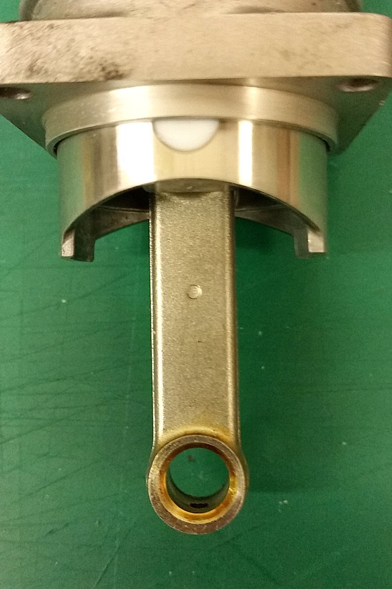
26 minutes ago, Martin Arnold 1 said:
All saito singles are pretty much the same, here is an 82 rod, having a mark on both sides would just confuse things...... Simple dot faces forward.
The six different Saitos I have (from 72 to 180) have different strokes, so I expect the con-rods are generally of different lengths, even if this is rather subtle - hence perhaps a need to differentiate them in other ways.
-
6 minutes ago, Martin Arnold 1 said:
No Saito rods have a dimple that should face forward.
Does that preclude a mark on the other side? Also, could it be that conrods for different Saito engines are marked in different ways so that they don't get put into the wrong engines!
-
I thought the consensus was that this mark was cosmetic, because it sanded out. Is it not possible that it is a deliberate mark to ensure the con-rod is mounted the right way, or to assist with the timing alignment?
-
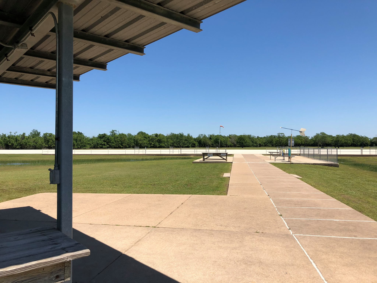
1 hour ago, Steven S said:
Here's one of our pilot boxes right now. We just taxi out on pontoons or skies from the sun shade.
There are five of them, each roomy enough for a pilot and a spotter [for when times are busy].
Where is this?
-
41 minutes ago, kevin b said:
Gosh!
They even have platforms, so they don’t have to stand on the grass.?
Actually, its to keep out of water after heavy rain.
-
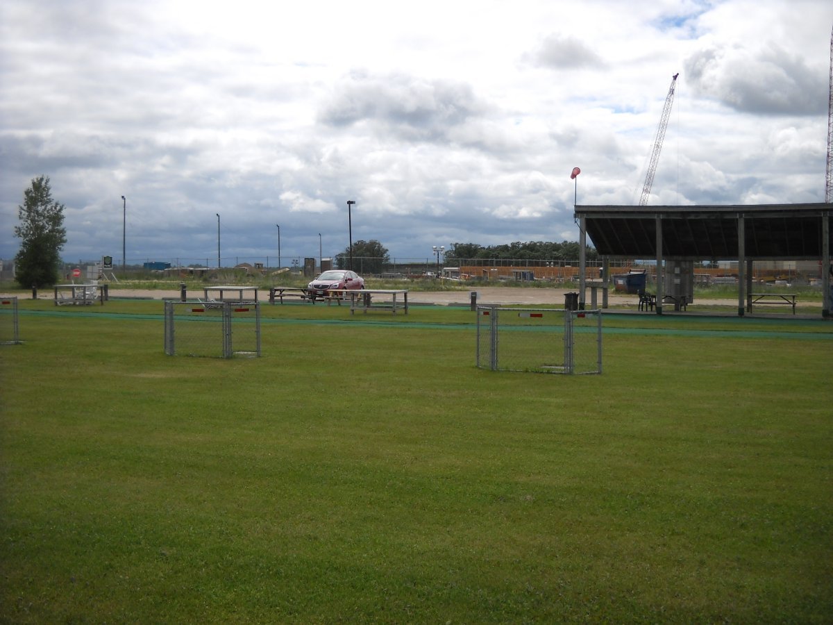
59 minutes ago, Geoff S said:
The pilots seem to be a long way apart for easy communication with each other. On the rare occasions when I've flown with several other pilots (often strangers as at Buckminster) all the pilots stood together almost shoulder to shoulder - say a 1 to 2 metres apart.
The distance between the pilot stations in the original layout was quite small, and when the changes were discussed one of the issues that came up was indeed the communication between the more spaced out individual pilot stations of the revised layout. A few trials showed that this was not a problem between individual pilots. The big advantage of the new arrangement was allowing for pilots who are all flying to together (e.g. formation flying or pseudo-combat) to be huddled in the larger stations, as shown in the following picture. I notice in this photo that the club has now added protective fences in front of the wider pilot stations.
-
1
-
-
5 minutes ago, EarlyBird said:
We have two cones which define the pilot box. All pilots fly between the cones, it's the rule. Our field is all cut short and the advantage of the cones is they can easily be moved so that the flight line is into wind. The first few pilots to arrive negotiate the flight line direction between themselves. As I am usually first, being an early bird by nature, I move the cones to suit the wind and take the blame from later arrivals who don't like the line. Water off a ducks back to me ?
Moveable cones are really handy as they can easily be moved as the wind changes, the sun causes a problem with my chosen line, or the late arrivals make a song and dance about it.
On show days and event days we have plastic fencing to define the pilot box, pits areas and the line beyond which the non involved should go. Unfortunately some members see the fencing as a hazard that they can't cope with so they avoid the event weekends.☹️
A defined pilot box is good and physical barriers can be an issue for some.
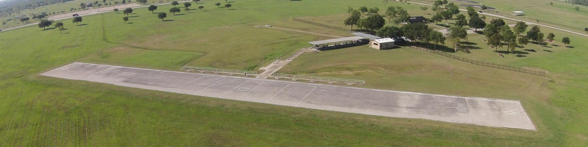
The best and safest set-up I have seen was at the club I belonged to in TX. This used to have a series of protective fences on either side to the pilot stations, which were spread along the one side of the runway:
These stations were designed for one or two people each, although others could stand behind. These provided very good protection from the side and there was easy access to the front and rear, so there was nothing to trip over. Then the club decided they wanted some bigger pilot stations for groups, so some of the lateral fences taken out, so to leave some of the pilot stations as they were but with bigger spaces in between for groups:
-
1
-
-
1 hour ago, Lima Hotel Foxtrot said:
What a disgusting attitude.
Why on earth disgusting?! For rubber bands, model shops are not the only choice.


Another effect of higher than normal temperatures
in Chit-chat
Posted
I had a tire blow out on my Toyota Prius a few years ago in Texas. I had parked it on black tarmac in the midsummer, midday sun for about half an hour. When I drove off the car rapidly developed a repetitive bumping sound, as though something was stuck in one of the tires, and the car was rising up and down slightly as though what was stuck was protuding downwards. I stopped the car, and had a good look round and could see nothing stuck in any of the tires. So I drove off again and hadn't gone more than a few hundred yards when then was an explosion - a very loud bang, and the car immediately slumped down on one side. A tire had blown out completely - there was a flap about four inches in diameter hanging out from the inner side wall. I put on the spare tire, and took the car straight to the local Toyota garage and they said they had never seen a blown tire quite like that. Incidentally, I had just had the car serviced before this happened, so I think the tires may also have been overinflated before I parked the car on the black tarmac.