

John Rickett 102
-
Posts
342 -
Joined
-
Last visited
-
Days Won
10
Content Type
Profiles
Forums
Blogs
Gallery
Calendar
Downloads
Posts posted by John Rickett 102
-
-
Ok, I can see the build thread, thanks.
Laser's website has been up and running again for some time now, you could trying accessing it here
-
Richard,
Perhaps its early days to be concerned about engine substitution, although keeping the options open during a build is a wise precaution.
The smallest Valach is 60cc, so could possibly be in excess of the requirements for a Gull 4, which I doubt had a sparkling performance fitted with a Gipsy Major 1 in the 1930s. Kolm produce a 50cc single, I’ve got one in a 1/3 scale Leopard Moth which weighs 34lb, the power seems about right. The engine is one of the early ones and for some reason is now on its third set of front bearings in just under 200 flights. Kolm are now up to Version 4 of the engine so I imagine they've found the need to introduce some improvements along the way.
Apart from the bearings in my example, its a nice engine. Machined from solid it’s a slim design with the inlets and outlets at the rear in the same manner as a Laser. Its also shorter than a Laser 200i so may need less butchery to install.
I’m very interested to see how you get on with completing the Gull 4, you need to start a thread on this forum………

-
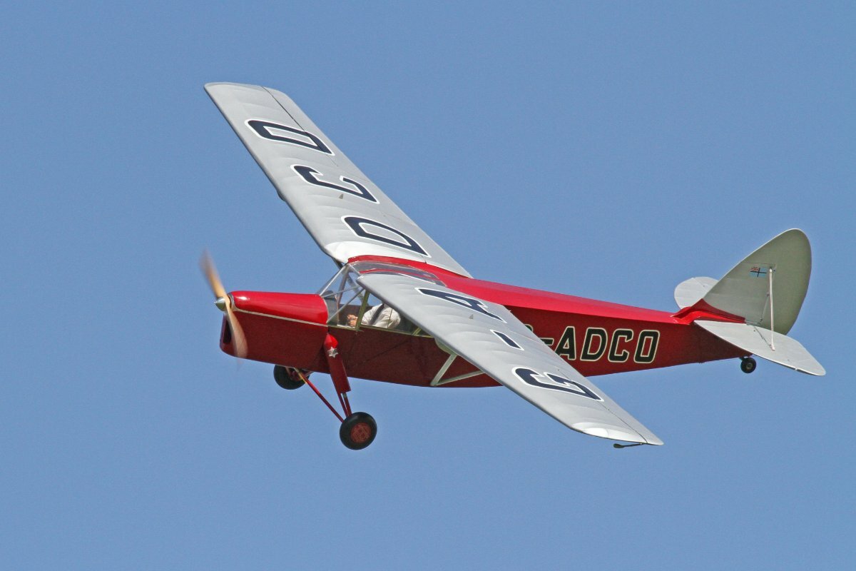
It’s good to see that another example of Edgar Percival’s talents is underway and that Arthur Searl’s creations live on. There seems to be so few Percival designs flying - the Mew Gull has been kitted before and available as a plan, but little else I can think of, what have modellers got against them!
The Vega Gull was a bit larger than the Gull 4, so at 1:3.7 scale the wingspans will be much the same at 117 - 118”. I’d expect a Laser 180 single and a 200 twin to have similar power outputs, so if the Gull 4 gets to be airborne first, it will be interesting to learn if (power wise) it was a good choice of engine.
This will be the third model I’ve built with folding wings, though the first cantilever wing. I’ve found it’s a speedier job to pack a model back into the van, or awning, when the heavens open than the alternatives of tubes or bolts. I accept they are more complicated to build and with all the fittings and screws required, the final weight tends to be greater.
I’m optimistically hoping for a weight of 25lb. I have a much flown Chrislea Ace weighing 25lb and powered by a Laser 180. The power is……adequate, but it is quite draggy. Percival designs were more streamlined so a small increase over 25lb should still be ok.
Thanks for the tip about using black foam as a method of directing cooling air to where its required. I’ll see how the motor performs before adding more baffles but hadn’t considered a material as simple as foam glued into position - something to remember.
-
Thanks Ron,
All's getting better by the day so in these dark months hopefully some meaningful progress will be made. It's just as well as Beryl is getting impatient to be airborne!
-
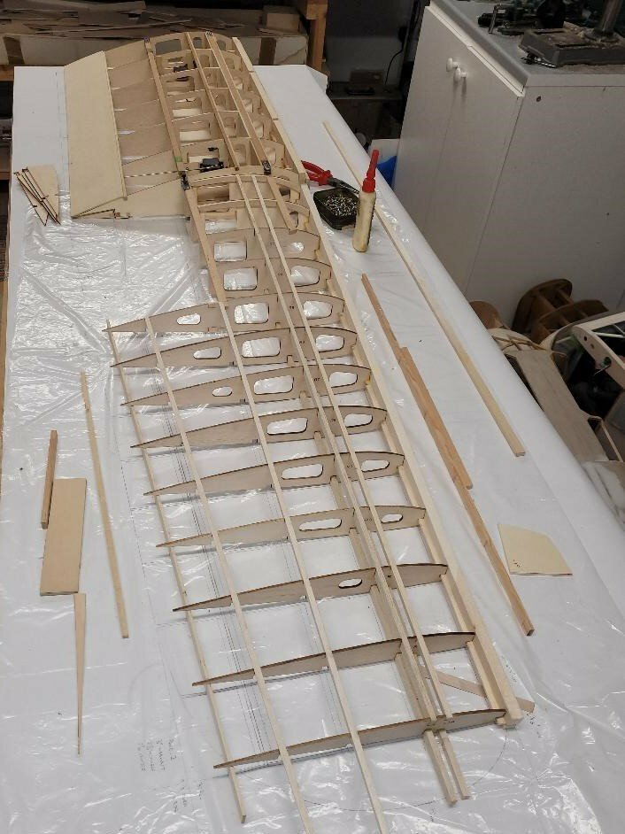
A tumble off a pushbike led to an enforced building board sabbatical. Well on the mend now though so what better physio for a poorly hand could there be than making a slight deviation from the planned order of things and starting on a wing panel.
LMA Member Bob Maltby had made an excellent job of cutting the ribs from a design drawn up in Compufoil 3D. Not having learned anything about CAD design, I find Compufoil a simple way of achieving the same thing when it comes to plotting and lofting a wing.
The picture shows the earliest stage of discerning that the few bits of wood are actually forming a wing. The large gap is where the ribs have to been cut off to allow for the wing fold supports to be added.
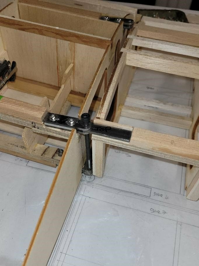
Its crucially important the hinges are positioned in the right place as three things are determined by their position:
· the dihedral (50) is properly set
· the wing folds without pinching
· the relative heights of each panel are correct
The centre section is being sheeted in 1/8” balsa with the outer sections in 3/32” so this adds a bit of a complication to what is already a hit and miss affair. I think that much playing with thin plywood shims will get the correct heights but there can be only one attempt at drilling the spruce/plywood spars. To overcome making a mess of it. the plan is to devise a method of holding the ¼” ply pieces in position without gluing so that if mistakes are made a new piece of ply can be substituted without having to cut out the previous piece.
At least progress is being achieved once again after a 4 week delay, I’ll just have to live an extra month to make up for it.
-
 4
4
-
-
Found them Frank, thanks....Molex.
It makes 4Max prices quite competitive given that smaller quantities of pins can be bought for only a small proportional increase in price.
I think that's the way to go.
Thanks for the assistance.
-
Excellent news Peter, thankyou.
I had heard that Phil Clark of Fighteraces had taken over the supply of Ashlocks but couldn't see them on his website, so good to know they are still available through 4Max.
-
Thanks for the further suggestions.
Yes, they probably came from Ashtec, I've still got some of their Ashlock connectors.
It a shame the coloured connectors are no longer available, they were such a simple idea, I'll have to resort to one of the other methods.
Thanks for the help.
-
Thankyou for the suggestions.
Each is a potential solution, though I was hoping that all else won't fail and that one of the knowledgeable modellers on here will know where these things can still be found.
-
Does anyone know of a source for coloured servo connectors?
Years ago, I bought some but cannot remember now who the supplier was and my little stock is just about exhausted. Ideally, the connectors would have the Futaba style orientation tab but that’s of secondary importance, the first is finding colours other that the usual black and red.
Never seeming to learn and quite frequently getting connectors crossed, different colours go a long way in preventing mistakes. Being a Futaba user, there is the option to use SBus, which I intend to do on the current project, however I’d still like to find coloured connectors if someone knows where they may be lurking.
Thanks.
-
Try GCPistonrings.com, its the same chap - Gavin Carter
-
2
-
-
One thing you could do, and I'm sure most radios are now capable of, is to mix a bit of rudder with throttle - its the digital version of side-thrust!
How much mixing can only be found by experiment. Put the mixing on a switch and fly at a reasonably high level until you are comfortable. If the radio is capable you may be able to adjust the gain from the transmitter, slowly increasing the rudder gain until you find a happy medium.
On the higher end radios, its possible to infinitely vary the gain. With Futaba gear its in AFR (Adjustable Function Rate) and can be a smooth 'spline' transition or a stepped 'point' transition.
I've applied mixing like this on biplanes before - it looks tidier than a lopsided front end and where you are effectively stuck with a built-in 'gain'.
Works well with vintage models too.
-
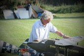
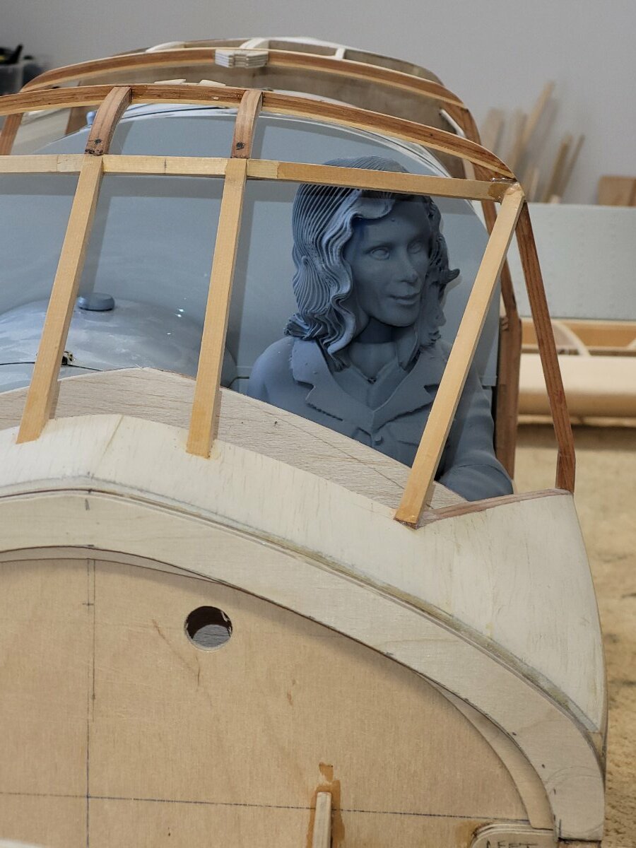
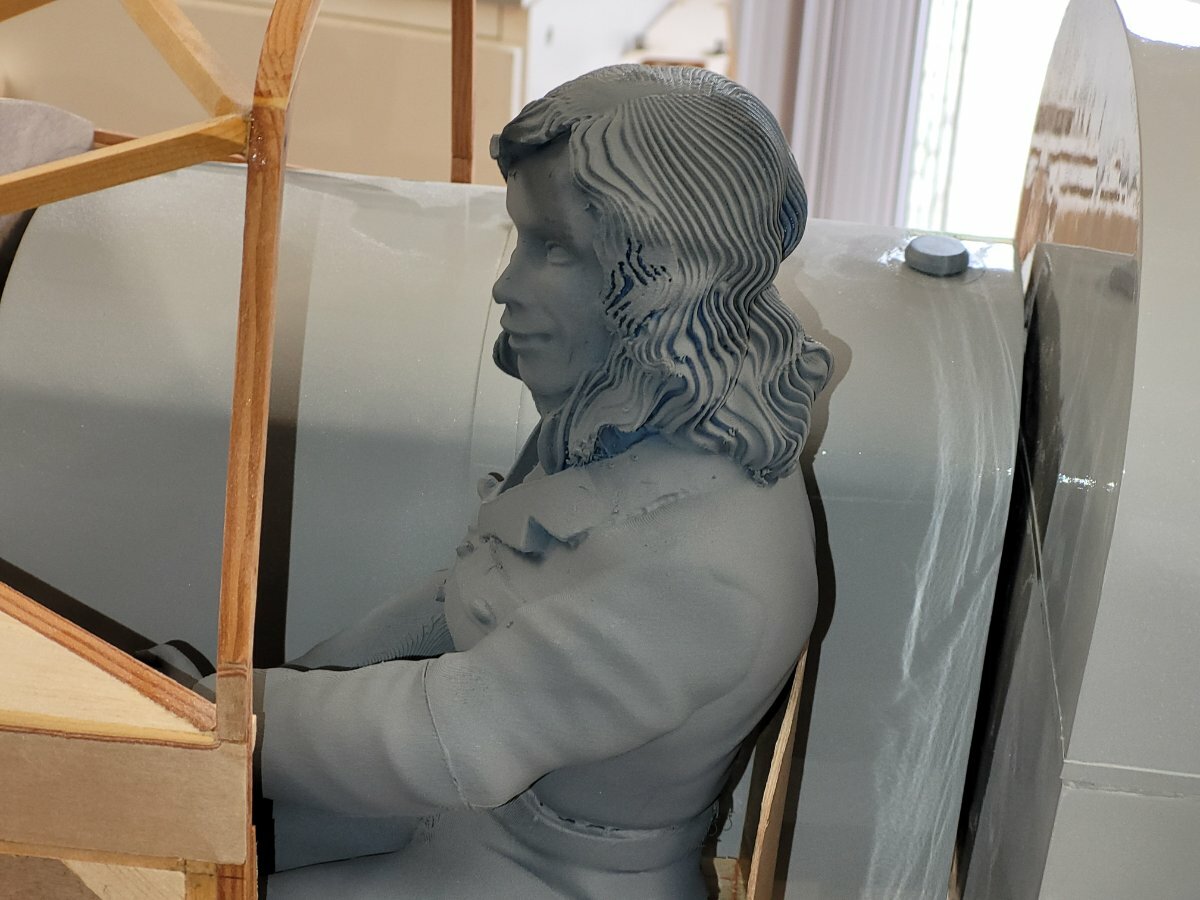
Beryl has paid a visit to the Percival works for a trial fit. Not much space left but that was probably the case in 1936.
Once she has been tidied up – white overalls, hair dyed and a spot of make-up I think she will look splendid.
Sean of Real Model Pilots has created her from photos found on various sites covering her life and exploits. Sean’s idea is that once satisfied there are no adjustments to make, she can be returned for final clean-up and painting…..that’s not a bad service. As it is, she has dropped in there nicely. The seat can now be covered and perhaps raked back a few degrees to make her look more comfortable.
Plan A is to make her, the seat, the column column and the floor as a removable one-piece unit held in with magnets (as are the tanks), that way seat belts and their fastenings can be added without having to work in a very cramped space. Having everything in the cockpit removable will help considerably in gaining access to the receiver, batteries and perhaps gyro which will sit in the wing well below the instrument panel. The wing centre section will be permanently fixed to the fuselage so the only access will be through the cockpit.
-
8
-
-
A variation on the previous posts is - tape together on one side, turn the sheets over and lay flat on a board, sand the faces lightly along the join line to fill any small gaps with the balsa dust, run thin cyano quickly along the line. After a few seconds turn the sheets over, remove the tape and run a do a second run. Sand both sides again to remove any ridges and you'll have two perfectly joined sheets in less than 2 minutes! This method is good for up to 1/8" balsa sheets.
Its remarkable that two sheets placed side by side can show how curved they can be, trimming them using a 3ft straight-edge is better than trying to make the tape hold them together.
-
1
-
-
The Big Wig is a trip down memory lane for me. I built one in the early 70s when attempting to teach myself to fly. The appeal was that it was a little larger than the usual trainers of the day and had ailerons and flaps. I thought the combination would make a slow flying model which would be easier to see on those all too frequent occasions when a model got further and further away. As suggested, it was powered by a Merco 61. Control was from a SprengBrook radio set I believe. It was built as exactly to the plan as I could manage, I didn't attempt to alter anything, I knew very little about aerodynamics and as it was a published design, It would surely do as described in the blurb.
Unfortunately, I quickly determined it wasn't going to be a good trainer for me - it was heavy, even covered in tissue, lively and fast.
Perhaps now it would be a nostalgic model to build again and I'm sure I could cope with the speed but at the time, after a few repairs which only increased the weight, it just joined the list of destroyed models in my quest to be a model pilot.
Good luck with the perseverance, I hope you get there in the end as you've made a fine looking model - its all good to see in an age when most flyers nowadays just want to open another big box and plug in the wings!
-
1
-
-
Presumably the ignition unit will be 6v, an unregulated LiFe 2S 1000mA/h pack will easily provide an average day's flying and be safer than a LiPo. No need either to remove for charging.
-
Use thin strips, sanding a slight chamfer on one edge to follow the curve. if the wood has to be really forced round the curve, the strips are too wide. Dampen each piece before gluing and progress both sides at the same time to cancel out the forces.
-
4
-
-
Frank, Have you tried neodym magnets. Since discovering them (all shapes and strengths) I wouldn't use anything else now...........and they are invisible.
-
1
-
-
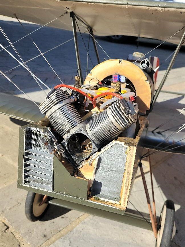
Ok Jon, thanks for the reassurance that engine operation isn’t going to be a problem.
Just to finish the coverage of engine cooling, these pictures show how the side and rear baffles close the gap at the bulkhead end. The major path for the air is now over the heads and through the gap between the cylinders. That gap would have been closed as well but there isn’t a convenient fixing on the engine, hopefully the forward silencer will block some of the air and help redirect it through the cooling fins.
-
Thanks for the reply Ron and the suggestion, its reassuring to know that you haven't had difficulty with priming. I don't usually use the wide open throttle method to draw the fuel through, but will remember to try that when the time comes.
-
The cowl has been trimmed to fit the bulkhead and the supports made.
Providing mounting points for a fibreglass cowl, I always seem to find a bit of a challenge if it’s to be durable. The rear of the cowl stands proud of the fuselage to provide an air escape path; for the model this meant the supports would also have to stand proud. I wanted these to be as unintrusive as possible and the holes not right at the edge of the cowl which could easily split with use. The method adopted was to make the supports from best B&Q steel strip with an additional lug brazed on to provide a thicker threaded area.
Trying to get the supports in the exactly the right place when the cowl itself was preventing access required a bit of head scratching. The problem was compounded by the cowl having a sharper taper than the fuselage immediately behind. The remedy was to mount the supports on a ¼” ply base which could be worked on, on the bench and later glued into position. The additional ¼” brought forward the mounting holes.
Maintaining the position of the little lugs while brazing (silver solder) was overcome by forming a simple jig and cutting down to size afterwards.
The holes were tapped M4.
Four mounts at the side and one underneath seem to have provided rigid support.
The intake duct was laid up using 50gm cloth over a simple sheet balsa form which was covered in parcel tape and given a couple of coats of release agent. A sharp tap with a toffee hammer (on the former not the fibreglass!) released it easily after curing for a day.
The duct was then sanded to fit in the cowl. It was quite a fiddly job getting it into the correct shape to fit round the engine and line up with the existing ducting. I ended up repeatedly taping it to the cowl and eventually, by trial and error, achieved the final shape as seen here. Once satisfied with the shape, a further layer of 100gm cloth was laid on including some carbon tow for good measure. There’s bound to be some vibration in this area so getting the ducts as stiff as possible and rigidly mounted seemed good practice.
The intake duct shown here tacked into position with epoxy resin but not yet reinforced with cloth.
The duct stands off from the cowl at the centreline to prevent air escaping around the exhaust side of the engine. All Gipsy installations I've seen have this arrangement, so its a small, scale touch.
A head-on shot where I wanted to show how the intake duct lines up with the ducting attached to the fuselage. Not a very good shot so you'll have to use your imagination!
I thought I was being smart in opting for the reversed inlet/exhaust arrangement, that is where the carb is on the cooling air intake side of the engine, but I now think I’ve built in a problem for myself with regard to carb access. Previous deliberations on this forum have stressed the need to ensure an adequate cooling airflow, particularly over the rear cylinder and head. Heeding the warnings, I’ve tried to make a ‘leak proof’ shroud to direct the airflow fairly tightly along the carb side of the engine; I’m hoping this will be successful, what I now realise though is that access to the intakes for priming and the idle needles for adjustment is not possible with the shrouds in place. The fuel lines also now have to be positioned inside the ducting.
The narrow layout from the rear exhaust and carb has always been a strong point in Laser’s favour, however with the production of the inline version, the rear layout may cause some challenges to practical operation. Normally an idle needle doesn’t require much adjustment but priming an engine is a different matter. I’m fortunate in having quite a few models though this can lead to considerable gaps in flying sessions and sometimes to the oil congealing in the fuel line to the carb and the needles. It only takes a few months of inactivity for oil congealment to manifest itself. Pinching the fuel line for the last stop of a session doesn’t prevent this. Also, on a scale(ish) model, with an all-enclosing cowl, adjustment may have to be made with the cowl removed and then hope that refitting doesn’t alter a setting.
If I had thought about it properly, the less troublesome option would have been the normal inlet/outlet configuration, which would have put the carbs outside the ducting.
There is little significant problem with Lasers having the inlet on the right (engine upright and viewed from the front) in inverted Gipsy Major style cowls, so why did I give myself the headache!
Routing a couple of pipes to enable squirting some fuel directly into each intake could be a possibility for priming but it won’t solve an oil congealed situation, for that the fuel lines will have to be disconnected and some neat fuel blown through. Time will tell if trying to get the engine started, particularly after a lay-off, and keeping it cool is going to be an awkward affair.
To try and get some data on what is an acceptable cylinder head temperature, I had fitted Powerbox temperatures sensors to a Laser 200v installed in a DB SE5. The engine (until I broke it!) ran fine with no inclination to overheat. The only convenient mounting points for the sensors were the rocker box retaining screws – not ideal but hopefully would provide comparable data. My Futaba transmitter gave a maximum temperature of 1800F (I’d have preferred degrees C but height is measured in feet and the user has to choose metric or imperial measurements throughout, there is no mix-and-match with Futaba). Armed with the knowledge that 1800F won’t cause problems, I will fit the sensors in the same position to the 200i and see what’s recorded, that’s still a long way off though.
-
4
-
-
Ok Jon,
I understand - No Loctite.
Thanks for the offer to repair, I'll probably accept that as, apart from the damage to the crankcase front face and seating area for the O ring, the rest looks like it can be overcome with a bit of skill - it would be a shame to scrap the engine if redeemable.
I'll see what the condition is of this other engine, I guess it could do with the bearings also being replaced as its been used and has been sat around for some time.
As a matter of interest, how tight is tight when tightening the screws into aluminium?
-
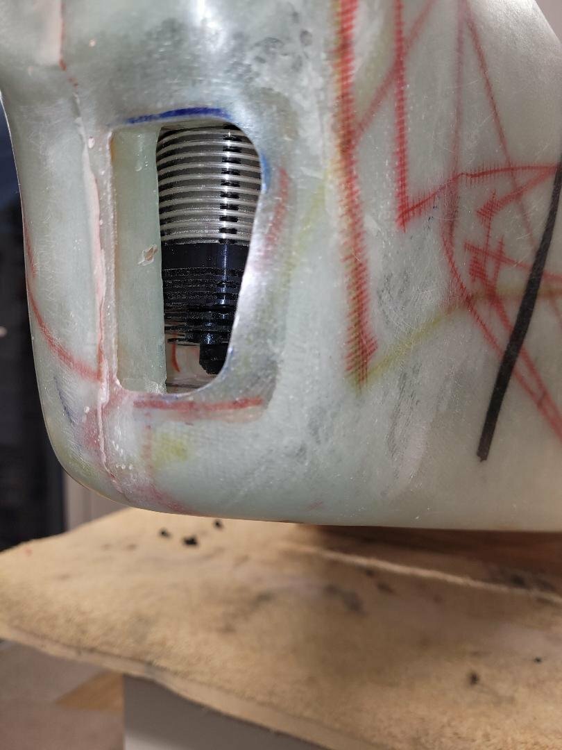
Here's a lesson for Laser lovers. If you change the bearings, make sure the screws are fully tight and use plenty of Loctite.
I'd changed the bearings about 10 flights ago (for stainless ones) and all was well until a noise developed immediately after take-off, the immediate plan was a tight circuit and land but there wasn't enough time before the front housing departed.
As luck would have it, the housing was found. The crankcase is a bit of a mess though the bearings and housing seem fine. There is a score on the crank pin, its probably not done much good to the conrods either.
Fortunately, a fellow club member has offered another twin that he's had sat on a shelf for some time, so the situation is recoverable.
The cowl was lost to the wheat crop, that will take the longest to remake.........apart from that it was a nice day yesterday.
-
 1
1
-
-
The fine weather earlier this year meant there was plenty to do away from the workbench, but with the recent cool and rainy weather a bit more progress has been made. The cowl seemed a good thing to get on with as it is something that can be progressed in small stages.
The Vega Gull will have a fibreglass cowl, it’s the only material I know which will stand up to the harsh environment of the engine, fuel and exhaust.
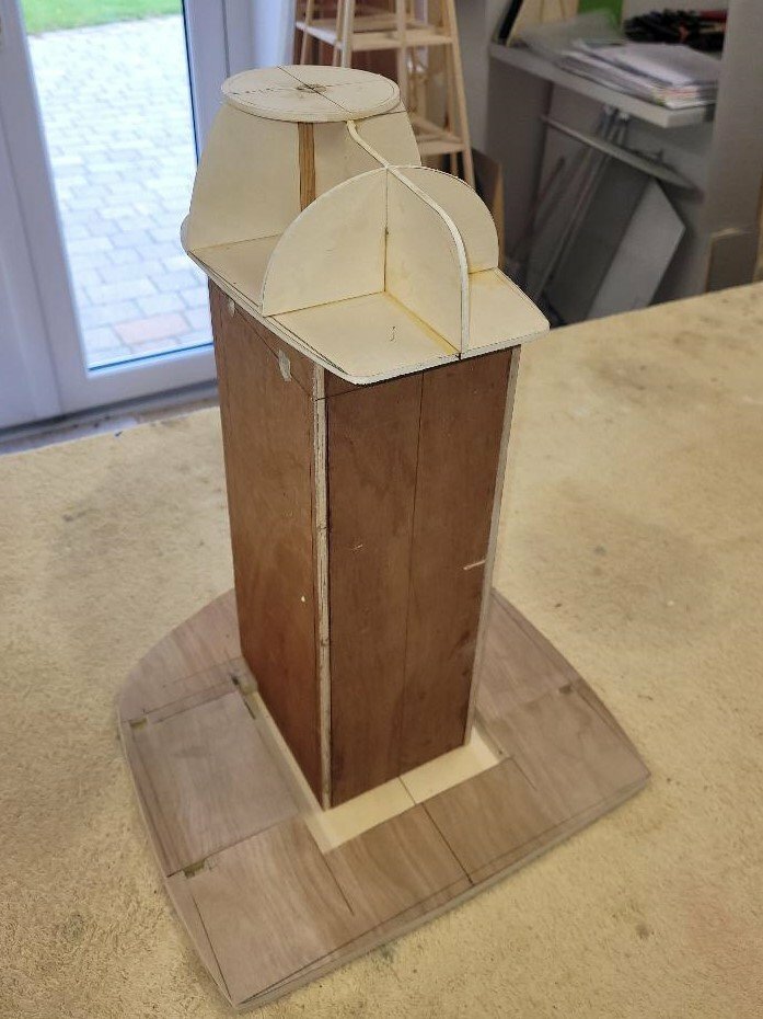
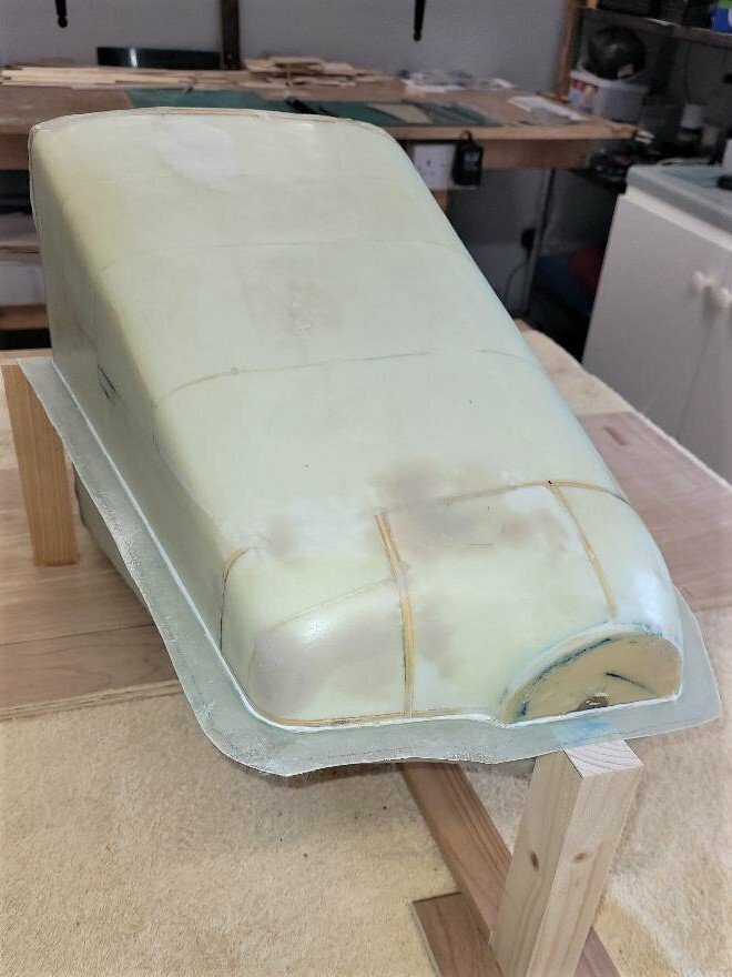
The plug was made by using the principle shapes of the rear bulkhead, the rear of the nosebowl and the spinner. Its 16” long and 12” wide so needed to have a substantial ‘skeleton’ to hold the shape while the foam blocks were being added. Cheap, low grade plywood from sources such as B&Q is adequate for this job.
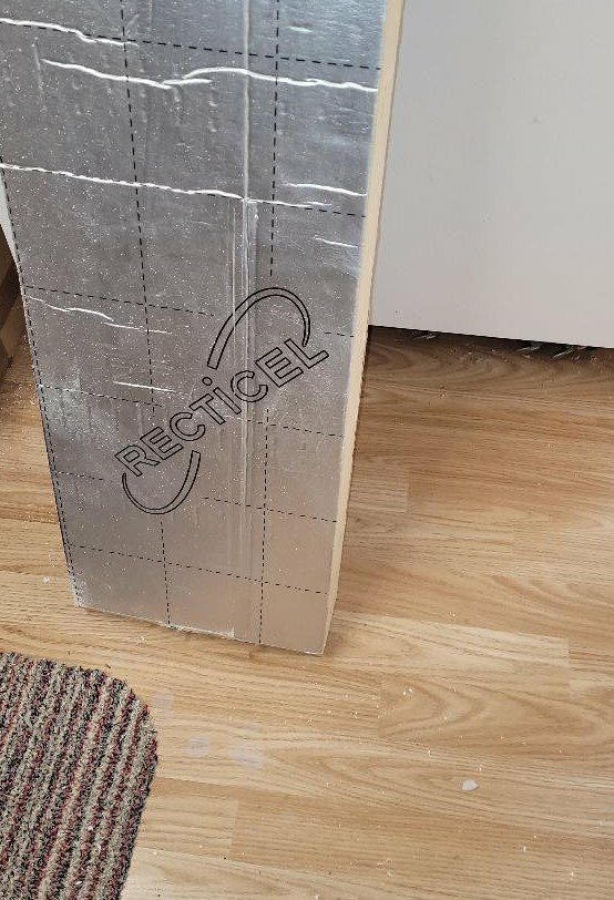
Recticel floor insulation, cut into manageable blocks and with the aluminium faces removed in a bandsaw, sands easily and being left over from a house build, cost nothing this time.
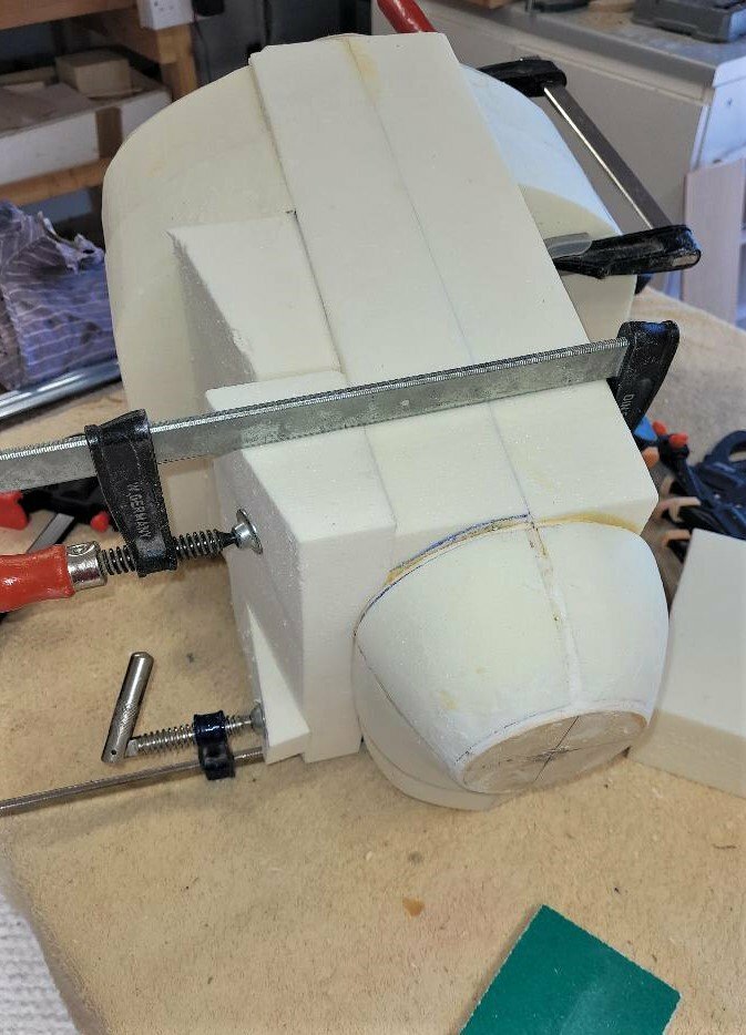
The blocks were glued using ordinary yellow modelling glue. Once dried, the glue is a bit harder than the foam so care needs to be taken not to end up with ridges.
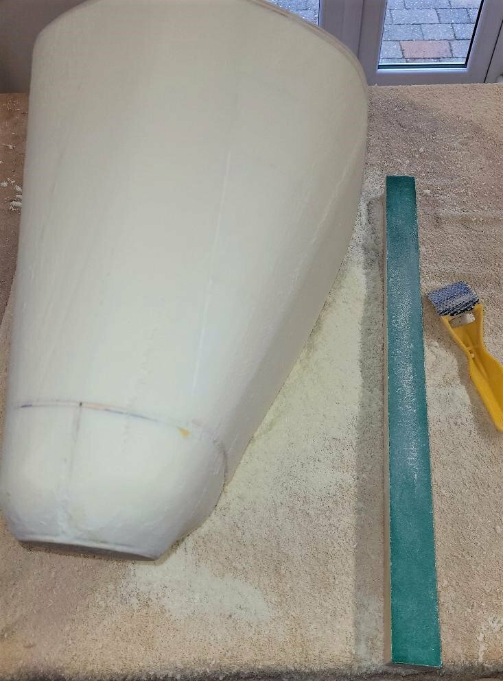
Apart from the compound curve of the nosebowl, the bulk of the cowl is single curvature so a long length of wood with some 180 grade glasspaper glued on, made a suitable sanding block. A small Surform for the curves and for initial whittling down, soon got the foam into shape.
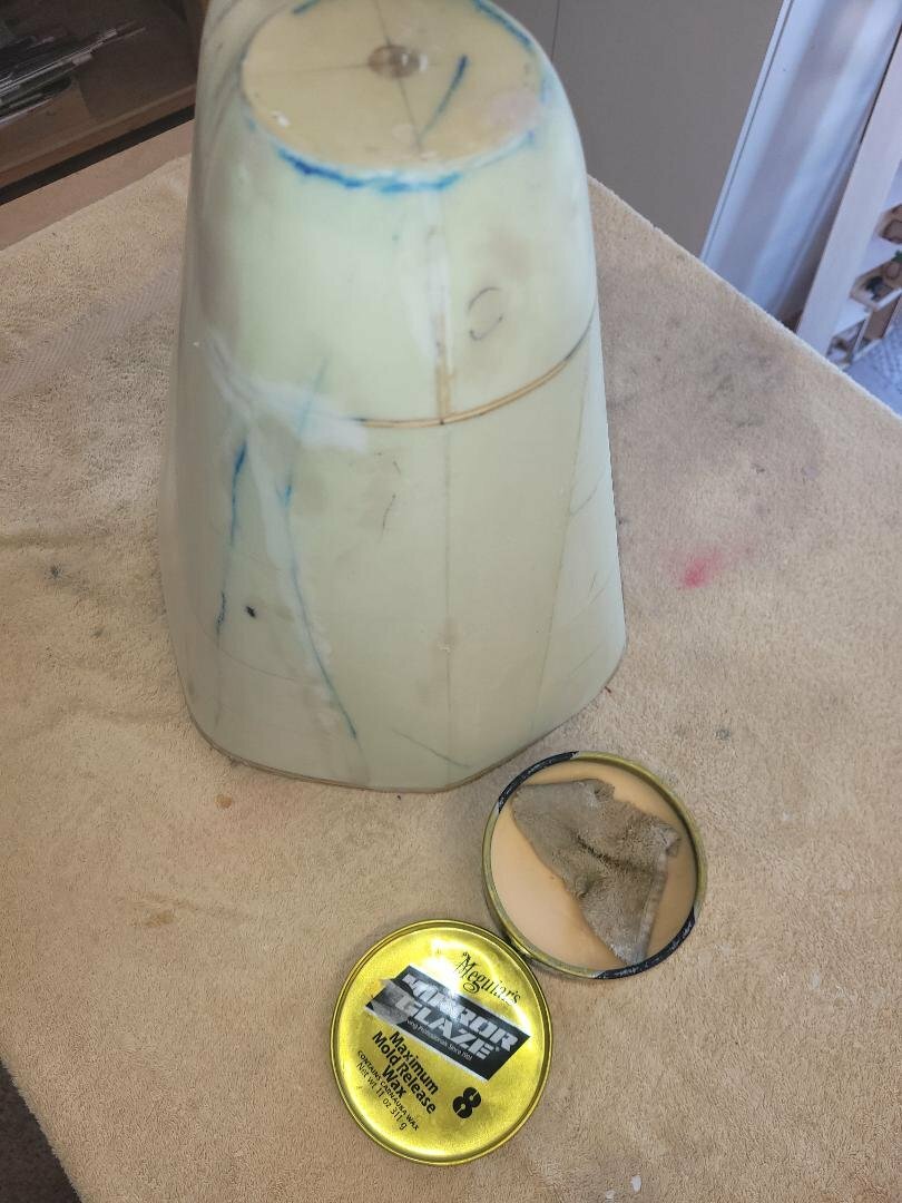
The plug was covered in a single layer of 80gm cloth. After hardening, the low spots were corrected with Isopon filler and sanded smooth.
Eight coats of Meguiar’s Mirror Glaze release agent (wax) were applied, buffing in between each coat to build up a good layer. The instructions on the tin only recommend three to five coats but experience from doing this quite a few times says the more the merrier; it’s a nice smell of wax polish, just like you remember your granny’s house, so not an unpleasant chore!
The parting board and support frame were made from various ply off-cuts, the parting board covered in parcel tape and the gap sealed with decorator’s caulk. To my mind caulk is better than plasticine or Polyfilla as the excess can be wiped away with a damp cloth and once it’s served its purpose, can be peeled off without leaving a residue.
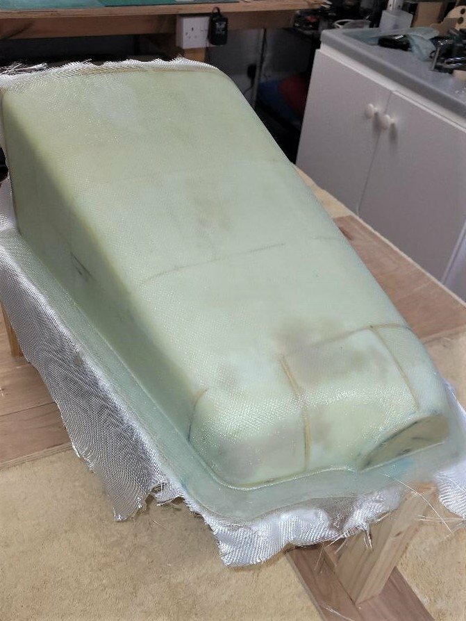
Strips of 50gm cloth were laid -up first, tucking it tightly into the 90O flange bend. This was followed up by 4 layers of 100gm cloth.
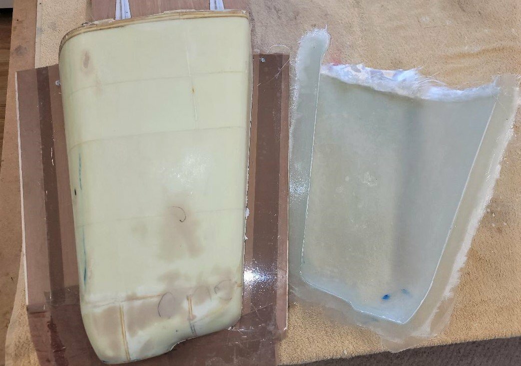
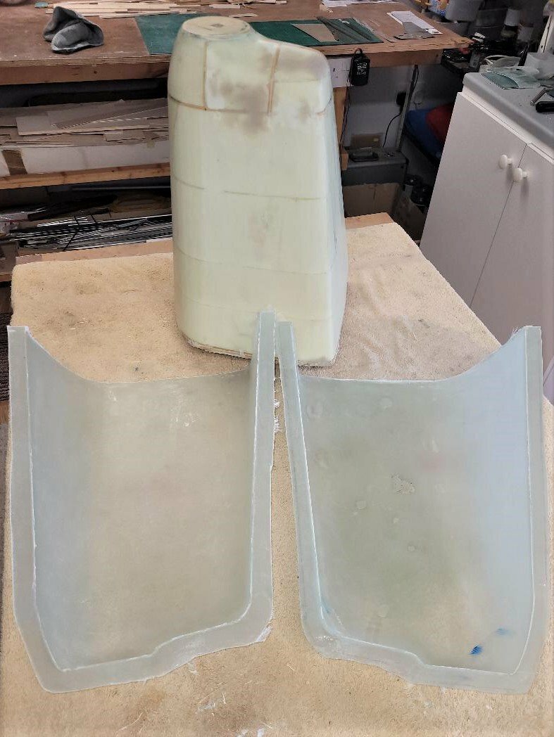
A day later, after the initial hardening, the first half of the mould parted cleanly from the plug.
The excess cloth was trimmed off, three coats of release agent applied around the flange area and then the plug was reinserted into the mould. A simple jig was made to keep the mould tight to the edges of the plug and then the joint was sealed once again with decorator’s caulk.
Unsurprisingly perhaps, the second side lay-up was exactly the same as the first.
One day was allowed for the resin to harden and then the other mould half was freed from the plug. My method of separating the parts is to gently work into the gap a ¼” strip of 1/64 ply which has been sanded to a chisel shape. If all is well the separation can be viewed through the fibreglass, with an opaque appearance as the parts separate. On a piece like this, I start from the rear and push the ply strip into the gap as far as it will go, without undue force, then work round the whole rear gap. Do the same for the flange. Once a clear air gap has been formed for half the length of the piece, a bit of thumb pressure under the flange will usually separate the remainder……satisfying to behold!
The two halves had their flanges cleaned up, drilled for the clamping bolts and then given eight coats of wax. Once bolted up, the seam area was given a further two coats of wax in case any damage had been caused to the layer with handling.
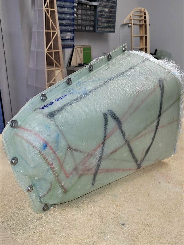
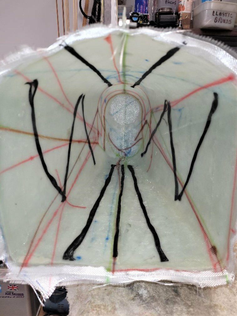
The cowl was laid up with 1 layer of 80gm cloth initially, followed by 4 layers of 200gm cloth. Different coloured felt tip pens were used when cutting the cloth to help identify the edges of each piece once in position and wetted out. I’ve found that if this is not done, it can be a hit-and-miss affair to get an even covering especially with larger moulds which require quite a few pieces of cloth in the lay up.
For good measure some carbon tow was laid up to stiffen the flat sections. Who knows if this has contributed anything, but as I had lots and the weight is negligible, it only extended the process by a few minutes.
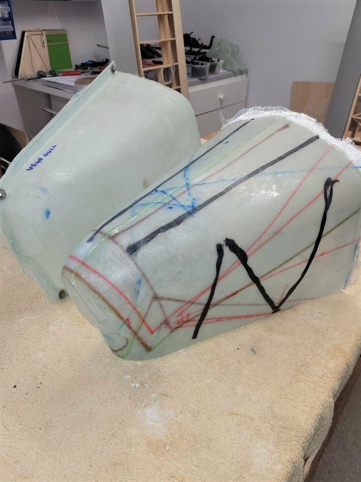
This is the cowl as it came out of the mould after 15 hours curing. All those coats of Meguiar’s paid off as it popped out easily. In its unfinished form here it weighs 527gm, which seems reasonable to me. It now requires the back edge trimming to fit the fuselage bulkhead, holes cutting for the engine and oil cooling intakes and the carb air intake. Once it’s in position, some fibreglass ducting will be grafted onto the inside of the main air intake to align with the fuselage mounted ducting to try and ensure the all-important cylinder cooling takes place.
Although quite a lot of work for a one-off cowl, if anyone ever feels silly enough to want to build a ¼ scale Vega Gull I could supply a cowl for a fortune making price!
-
9
-


Percival Vega Gull
in Own Design Project Blogs
Posted
The right hand wing hinges have now been lined up, drilled, the dihedral set and all permanently screwed into position.
Besides the main spar webbing (1/8" balsa), webbing has also been put in at the roots where I imagine the highest stresses will be.
Some 1/8" balsa, 3/8" wide has been added to the first two (liteply) ribs to provide a better gluing area for the sheeting.
The wing folds as it should but at this point I've no idea whether the other one will be level with it at the tips, so perhaps shouldn't get too carried away with the sheeting and making the screws unreachable. The leading edge will be sheeted to form a D box as well as the first bay of the outer panel. This won't be scale as there doesn't appear to be any sheeting in this area on the real thing, but practical is sometimes better than sticking tightly to scale in my opinion.
The distance between the upper and lower hinges is 55mm, I was concerned that there could be some flexing with the wing hung off this arrangement, but am relieved with the rigidity, even without the sheeting.
A start has been made on the folding section, this also carries a split flap and will house the servo. 1/2" x 1/4" spruce strips will carry dolls house brass hinges to enable the section to fold right over onto the wing.