

John Rickett 102
-
Posts
342 -
Joined
-
Last visited
-
Days Won
10
Content Type
Profiles
Forums
Blogs
Gallery
Calendar
Downloads
Everything posted by John Rickett 102
-
Thanks again for the suggestions. I can better see the problem now, the sensor element is encapsulated in the ferrule part of the tag so there is probably quite a temperature drop from where the tag is bolted to the head, the tags have now been repositioned. Unfortunately the PowerBox bare sensors (6619) don’t seem to be stocked by any of the large on-line model shops. Before buying directly from PowerBox, I’ll try applying heat conductive silicon glue (arriving tomorrow) and, after degreasing the area, encase the whole tag with a blob of the stuff, hopefully that will conduct the heat to the sensor. Ron, What temperatures are you recording?
-
Thanks Chaps, You're correct that the temperatures are almost certainly higher than indicated, I'll see what can be done about getting a better contact/heat transfer. The surprise for me though was that the front cylinder is hotter than the rear although the fuel draw is the same, so it doesn't seem as if there's more fuel going through one cylinder and keeping it cooler. I don't have an explanation why there is a temperature difference (which I can feel) and why its the rear that's staying cooler. Regarding the cylinder bolts holes, each bolt is just about touching the cylinder wall so there's no room for the tag unless half of each one was removed. The bare sensors could be an answer though, thanks for pointing out that they exist.
-
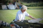
Brian, There is limited scope for fitting sensors, the obvious choice would be under one of the cylinder screws but access is impossible. Each sensor is therefore mounted on the exhaust clip screw, so should be shielded from the propwash. The tag is positioned against the head (under the clip) so at this point, very close to the exhaust, you’d think they would be seeing a hot part of the engine. I tried to mount each exactly the same, see the pics below. After running, both cylinders are hot, I can only touch for a second or so but enough to know that the front cylinder is getting hotter than the rear. Front Cylinder Rear Cylinder
-
An interesting result – the engine has now had three tankfuls through it and always the front cylinder runs hotter than the rear. At first I thought I had crossed over the temperature sensors, but not so, on stopping the engine the front is hotter to the touch than the rear each time. Typical temperatures are 45C on the front and 34C on the rear (ambient temperature 19C). Another interesting observation was that the temperatures would rise a few degrees when allowed to idle for a few seconds. I don't have reason to doubt the Powerbox sensors as they will both show the same ambient temperature once everything has cooled off. There is a two tank installation with the tanks easy to view (with the cowl off) and both tanks were depleting at just about the same rate and I couldn't differentiate between the amount of the smoke from each exhaust. Peak revs, as best I can measure with my little rev counter, are 6300 on a Falcon 20 x 8 wood prop.
-
Thanks Ron, Its had two tankfuls through the engine now, another two to go today, then it will be baffles on and cowl fitting before trying again. Plan A was to fit a 20 x 6 prop but the spinner nut I had bottomed out before the prop was tight. I had a 20 x 8 so fitted that and it seems ok. I don't want a quick model so may buy a 21 x 6, how much have you loaded up your engine?
-
One small feature which I thought worth incorporating, as it could be useful and added only a few grams, was the door retainer (for want of a better expression). Being a tail dragger, to open a door would have meant overcoming some of the door weight as well as a nuisance with the door always trying to close. A spring-loaded cable ran from each door to the engine compartment, the simple geometry causing the spring to have no effect on a closed door, to providing maximum assistance once the door was partially open.
-
Before reinstalling the engine and wiring up the plugs to put them in series, a quick test was carried out to make sure the powerpanel would drive them and find out what current would be suitable for the OS F plugs. The plugs have a decent glow with 2 Amps set.
-
From the previous discussion, I thought it was worth ensuring that the anodising had been fully abraded where the copper washer seats. The recess is 12mm diameter, so a short length of 12mm dowel, conveniently lying at the bottom of the scrap wood box, was pressed into service as a simple mill which wouldn’t skid sideways as soon as it was rotated. A glowplug copper washer is 5/16 diameter so a same size bit of 120 grit glasspaper was stuck to the end of the dowel. In for a penny as they say….having plugged the holes with tissue the dowel was put in a portable electric drill and set to the lowest speed. A few seconds later bright aluminium showed around the plug holes, I think that will work.
-
Ron, I like the idea of the series connection as you've done it, it eliminates a third wire. I'll test to see that the powerpanel will drive two plugs in series, if it does I'll make up a new loom. Paul, in effect the post of one plug is positive and the post of the other is negative, the platinum element is not polarity sensitive. the engine casing acts as the conductor between plugs.
-
Ok Paul, Would that be a direct fit, even though produced for a spark plug?
-
Ok Chaps, thanks for the suggestions and I accept Ron that all your engines will conduct as expected. I don't have any slot drills, however I've tried Brian's suggestion of cutting through the anodising by using a brand new 1/4" drill turned by hand. Its obviously done some good as there is now continuity showing on a multi-meter. The contact area must be very small but if its enough to pass the current of a glow plug, then we are back in business. For interest, its not possible to fit a tab washer and fly lead as the plugs are well recessed into Laser heads, the recess is 12mm diameter, only marginally larger than a socket spanner.
-
Thanks Ron. My engine has all of each head anodised, including the plug threads, consequently the current cannot pass through the engine body. I've tried screwing and unscrewing a plug several times to see if it would wear away the anodising but it hasn't. I recall that on the OS LA (blue) engines, the plug seat and threads were not anodised, presumably because of the problems it would cause, why Laser saw fit to anodise all of the head is a mystery to me!
-
Thanks for the suggestions. I don't know how thick the plating is, but the plugs will screw in by hand as normal, so the prospect of removing material with a tap sounds as if the plugs could end up a sloppy fit. Ron, I use a 12v powerpanel so can vary the current as plugs require. Regardless of the voltage available if the anodising is acting as an insulator, 2.4v surely isn't going to breakdown that insulation? Do you use remote connections on your engines, and have you found that connecting in series rather than parallel is the answer. I don't understand the logic but could try connecting the plugs in series if you've found it works, I would expect the powerpanel will still drive them.
-
The engine, tanks and remote glow connections have now been installed ready for ground runs (with the cowl removed). I have a PowerBox temperature monitor which can take up to 5 inputs. The sensor part is a metal tag, to be used similar to a washer under a screw. On a Laser, the closely drilled holes for the cylinder head screws preclude fitting the sensors where ideally they should be. Not wanting to drill holes in a cooling fin (as PowerBox suggest) the exhaust mounting clamp seemed the second best choice. If all is well during the first flights the monitors could be removed, or at least switched off, but should give some indication that better cooling may be needed. Initially I was going to just monitor the cylinders, then thought that since I have the sensors (which each only weigh 4 grams) I might as well track the heated air exiting the engine compartment, so fitted one where the air passes through the main bulkhead and another just inside the rear lip of the cowl, which is about 7” back from the bulkhead. The logic of this being, if there is a significant temperature difference, it may indicate that there is insufficient air passing through. I’m hoping (ever the optimist) this will be a temporary arrangement and that the wiring can come out if all is well. When I think that my first venture into radio control was single channel with a rubber driven escapement, I’m amazed at the advancements which have occurred within the hobby – at least it keeps the mind active when I often think I’m on the verge of that slippery slope of losing my marbles. Keeping the brain active has been necessary trying to get the engine started. A good supply of fuel, but for some reason no glow using my method of a remote set-up, which I’ve used many times before. Having checked all the connections, I abandoned the remote glow and used a glow clip instead – instant success, though only on one cylinder as I’ve only one glow clip. I tried the other cylinder and had the same success. It finally dawned on me that the black anodising was preventing using the engine as an earth return. If there is anyone reading this drivel who has one of these engines and had success with a remote glow connection, I’d be very interested. Also does anyone know how to remove the anodising around the plug hole and threads without causing damage? I can move the earth connection to another point instead of an engine bearer screw but there is only one place a glow plug can be fixed!
-
Thanks Ron, Hopefully it will, though needs some testing first. I'd like to come along with something which qualifies if not the Gull.
-
You’re correct Brain that channels 5,7,8 and 10 are the preassigned ones. 5,7 and 8 are for setting each axis gain, I probably won’t require rudder to be on a gyro but will leave it available until after the model has flown. I won’t use the AVCS mode (heading hold) so have inhibited that in the transmitter but it doesn’t free up a channel, just means that two positions of a 3 position switch brings each gain to 0%. Channel 10 is for recovery mode, which I din’t want but as soon as I tried to assign a function to it (flap) it affected the elevator output in that the elevator would suddenly jump to a new position at the end of flap travel! I tried assigning other functions to channel 10 but it always affected the elevator output so its clear to me now that channel 10 can only be used for recovery mode. I’ve ended up with channel 9 (elevator 2) assigned to the left outer flap, channel 11 (rudder 2) to both inner flaps (y lead), and channel 12 to right outer flap. The landing lights use the switched DG1 output. Its all hooked up and working now so should be ok, I was just a bit surprised to discover that the gyro ties up 4 channels. Some time ago I fitted a Futaba GYA460 gyro in a Wot 4 and played with the recovery mode – its amazing, it doesn’t matter what attitude the model is in, as soon as the switch is triggered, the model is instantly the right way up again. With the Vega Gull, plan A is to leave out Beryl and the tanks for the first flights, this saves 580gm (1.3lbs) and will shift the cg forward marginally….every little helps.
-
You're right of course Ron. I made up the long leads in the wings and centre section, looks like I'll need to spend some time making up the short ones now.
-
The wing registration letters have been sprayed on. I was pleased to find that there had been only one instance of paint bleed under a mask, this where the mask crossed rib stitching. Once the paint had been left for 24 hours, it was gently polished out with T Cut. To prevent paint bleed, some people advocate spraying the first coat with the surrounding colour, though I’ve found that if a very light coat of the lettering colour is sprayed first, then allowed to flash off for a couple of minutes, it seems to seal the edges. Paint bleed then only occurs where the mask has, without being noticed, lifted from the surface. The radio installation has now been completed but not looking as tidy as intended. I thought that putting all the units on a plate and mounting it under the instrument panel would keep the cables short as well as keeping the weight up the front. There seemed to be a lot of room but suddenly its got cluttered. If anyone has any ideas about how to install multiple units – receiver, gyro, magnetic switch etc and keep everything neat, I’d be willing to listen. Once the instrument panel, the tanks and Beryl are in place, the untidiness should be less apparent, but not looking very smart just now! As an aside, a Futaba 14 channel receiver was fitted which I thought would allow for each servo to have its own channel. I’ve also fitted a Futaba GYA 553 gyro and, while happy that it can connect to the receiver through SBus, which cuts down on the number of cables, I’ve discovered that 4 of the receiver output channels cannot be assigned as they are occupied (internally) by the gyro. To get round this, either the inner or outer flaps would have to be connected using a Y lead, I chose the inner ones as they are smaller and hope perhaps there’s less chance of overloading the channel output. The symmetrical installation of the flap servos of course meant that as one flap went down, the other went up. By preference Hitec digital servos had been fitted so it was a simple job to reverse the action of one servo. The more difficult task was having to trim the pushrod movements mechanically to get both flaps equal – awkward, given that I’ve buried the servos and pushrods in the wings.
-
Its quite satisfying when the previously made parts are finally added. The four moulded windows received from Sarik were trimmed and stuck into position using Deluxe Materials canopy glue. Sarik had made a good job of them, clear and with minimal distortion, much better than is usually seen with the canopies included in kits. The windscreen, doors and windows were extensively framed with what appear to be anodised aluminium moulded strips. Being a distinctive feature, it seemed important that the frames were replicated. To keep it simple, litho has been used. Its not ideal as the 20 thou soft aluminium follows every lump and bump but several coats of primer/filler rubbed down have improved the look. I deliberated for a while whether to fit, or even simulate, the many screws that were used to hold the strips. The originals look to be raised countersunk screws which would have been impossible for me to reproduce. Plain dome headed screws I decided would sit too proud and look ungainly. Also, while miniature cross headed (Phillips) screws can be readily sourced, it’s a different story for slotted screws. Phillips weren’t in common use until after the second world war and as this model is supposed to represent its 1936 heritage, I’ve opted to leave the strips plain. Weight was also a consideration, its amazing how quickly small details like screws can add up. The original weight target was 25lb but in trying to weigh all the individual bits, I think it will exceed the target now, lets hope it will come in under 27lb – we’ll see! To achieve the anodised aluminium (non-tarnishing) look, gloss back paint was applied, followed by chrome paint and then gloss Klasskote clear. This dulls the chrome effect and at the same time provides a protective barrier as the bare chrome layer is easily damaged when handling. From photos, Beryl’s aircraft seemed to have the rear window frames painted the same colour as the fuselage, but having seen pictures of other Vega Gulls with all the windows framed in shiny aluminium, I thought it prettier to do the same. A mistake was made here as, having masked the windows, I left the tape in place while first the turquoise colour was applied, then black, then chrome, then clearcoat. This built up the edges to such an extent that there is now a ragged edge where the tape has been peeled off. I think now it would have been better to spray the turquoise, then black, remove the tape and re-mask – too late now. I do not have any spray booth facilities so have to rely on decent weather, fortunately its been fine of late for painting outside. The major parts were spray coated with 2K primer/filler then flattened with 400 grade wet and dry paper prior to two coats of 2K colour. My wife was horrified when she saw the colour, I've tried to placate her by saying that tastes have changed for the better in the last 90 years, but history cannot be changed. Masks for the registration letters were produced on a vinyl cutter along with the Castrol and Messenger lettering. I imagine the nose lettering must have been added quickly and without much planning prior to the historic flight as symmetrical it certainly isn’t. Perhaps the sign-writer started on the left side and didn't notice the air intake until he got to the other side! Oramask 810 has been used for the lettering which seems fine at producing a crisp line on painted fabric. The Percival trademarks are waterslide transfers created by Nigel Wagstaff of Flightline Graphics. He does a really good job, sharp and vivid results, much better than can be produced using a standard inkjet printer. The transfers on the fuselage side should be on the doors but I seem to have made the doors a bit short, so there isn’t the space necessary. I’ve opted to fit them under the doors – no-one will know! Rather than put the transfers on top of the turquoise, each area was painted white and then masks were placed into position. Once the painting was finished, the transfers were carefully applied. It was quite difficult to get each positioned in exactly the right spot and I was reluctant to keep sliding them around in case they split or wrinkled, but somehow got near enough without damage. If going down the route of waterside transfers, its important they are sealed, but not just over-sprayed with any old lacquer. In the past I’ve tried a few sealers resulting in greater or lesser cracking. The one which works and is recommended by Nigel Wagstaff is Tamiya X-22 acrylic, this is supplied in 10ml bottles and is best applied with a soft brush. After a couple of coats, allowed to dry completely, it can be over-coated with a clear fuel proofer along with the rest of the model, if that is your wish. The wing and tail fillets have been glued into position using clear silicon bathroom sealant. I deliberated over using contact adhesive but there is only once chance of getting that right and it may not be my lucky day. I also considered epoxy though there was a possibility, as with any runny adhesive, that when the fillets were pushed into position, some of the epoxy would appear at the edges and be difficult to remove. Silicon has the benefits of being very viscous, allows slight repositioning and if used as sparingly as possible, could (perhaps!) be separated at a later stage. A few small blobs were applied and held in place with tape until the initial grab had occurred. I was quite pleased with the result, there is now a small gap between each fillet and the fuselage which gives the illusion of a removable part. Wing lettering to do next then the final fitting out can commence.
-
Thanks for the answers and yes, I'll start out with a 20x6.
-
Ron, Do you know what revs you get with the 18 x 8 please?
-
Sometimes the Saito would miss a beat and then continue running, at other times it would stop, Their recommendation (included as an addendum sheet with the manual) was to tip the model on its side after starting to clear the airlock - hardly a practical solution in a largish model. OS are not specific about the carb, only that it has been developed in collaboration with Walbro. I believe Saito said a similar thing at one time but their carb didn't look anything like a Walbro. Hopefully Ady will provide some clarification.
-
That’s interesting Ady. I would have hoped the 200i would be adequate for a ¼ (ish) scale Tiggie. What is the weight of your model? I’m building a low wing model and have a 200i to go in it. The expected weight is 26 or 27lbs so if your findings are anything to go by, the Laser could be well under-powered for the model, something I’ve feared for a while. I’ve considered the new Saito FG50 but am put off by their carbs, they tend to airlock and stop. Morris Mini Motors recognised this a long while ago and made Walbro conversion sets, I bought one for a FG30, it solved the problem but added over £200 to the price. The OS GF40 has a modified Walbro, how reliable have you found that? Also, the OS has a sticky-out silencer, did that fit in the Gipsy cowl, or did you perhaps get something made up? I apologise for the questions, but your findings are a bit concerning.
-
 Rudder to throttle coupling is an effective measure to counter a swing during the take off run. It doesn't need to be much. no more than 10% increase in throttle for full rudder deflection. If you want you could switch it out once airborne, though on the two models I have with this mix, I don't bother as a bit of rudder and the corresponding increase in the outer engine helps with the turns. I would think that just about any modern radio could accommodate that bit of programming and would be simpler than left and right hand propellers and making a starter run in both directions to get the engines started....unless you're talking about electric motors of course.
 -
A Laser 180 would be more than enough, I'm using one to power a 26lb model. The Bird Dog isn't supposed to be aerobatic but at 15lb I'd expect the Laser to give it a sparkling rate of climb, if needed. A 30cc petrol 4 stroke would also be suitable.

