

John Rickett 102
-
Posts
240 -
Joined
-
Last visited
-
Days Won
10
Content Type
Profiles
Forums
Blogs
Gallery
Calendar
Downloads
Posts posted by John Rickett 102
-
-
Danny, thanks for the kind words.
Any of the Hitec digital servos have the same programmable features, among the things that can be set within each servo are: reversing, end point, centre, failsafe position, servo speed. These things can be carried out with modern transmitters for the respective channels but if using multiple servos connected to one channel, then being able to set them within a servo can prove especially useful. You do need to buy a programmer though, I've had mine (HFP-20) for probably 10 years now. The current model is the HFP-30 which, as an example, is being sold by Steve Webb models for £72. There is a cheaper Hitec programmer, about £20, its not as straightforward to use but achieves the same results.
-
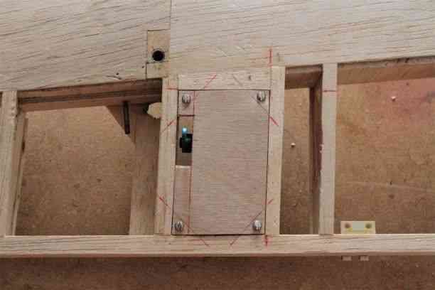
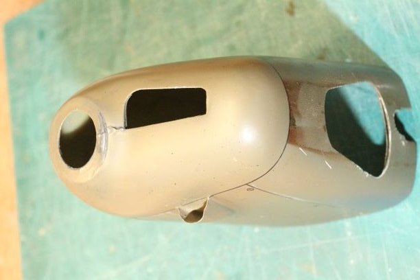
It turned out quite fiddly to fit in the servo but its done now so just have to copy the procedure for the other three wings. The hatch, which is a piece of 1/16 sheet glued to 1/64 ply, will be covered in 50 or 80gms fibreglass cloth to strengthen, stabilise and provide a flat finish for painting.
For reasons which don't stand scrutiny I'm prejudiced against servos which don't begin with Futaba, Hitec or Savox. The single advantage for me of Hitec servos is that they can be easily reversed (with a programmer) so there are no worries about how to hook them up. This model will probably have all the aileron servos driven from one channel so reversing, if necessary, can't be done in the transmitter alone.

-
In anticipation that the engines can be sorted out in the near future with new bearings and rings, efforts have been redirected at the outer wings.
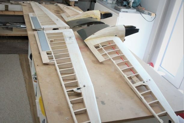
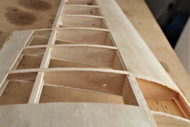
All the Solartex has been stripped off to inspect the airframe. There are a few patches of cracked sheeting and broken glue joints though they should be simple to rectify. The three main tasks for each wing are:
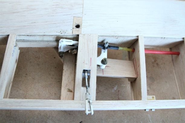
- Install a servo bay
- replace the rigging supports
- Replace the wing jointing tubes
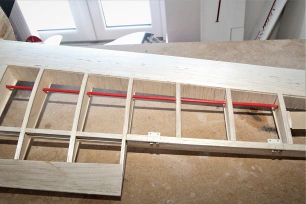
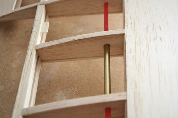
The easiest job will be installing servo bays so I've started on that. First thoughts were that the snake outers would make handy tubes for the servo extension leads but the the diameter is too small, so its out with the outers. Using a piece of sharpened brass tube which would slide over the outer it was a quick job to cut though the balsa and old glue to leave a straight row of holes for the cable.
-
 1
1
-
I don't think the engines are quite as cooked as the earlier pictures suggest. The previous pictures were taken in my workroom which has 'warm white' lighting, this has perhaps given the distinct brown appearance. The picture below was taken outside, in natural light and the staining doesn't look quite so dramatic.
I take the point that even though the engines generally run at half throttle, there could be a insufficient flow through the cowls so I'll look at fitting dams at the front of the outlet holes as well as shrouds for the cylinders.
I agree also that it would be prudent to replace the bearings, they have had to sit in contaminated oil for over 25 years now, castor and synthetic, and while being aware that Laser make fine engines but perhaps this is asking a bit much.......how long was the guarantee!
-
3
-
-
Jon,
Thanks for the assistance. The clicking sound is heard when the engine is running and only occurs when the engine 'pops' as happens if the engine is too rich and only at the top end. I'll change the plug and try again. I don't not suspect the fuel, the other engine ran a couple of days ago on the same fuel and seemed fine, that one peaked at 8800 on a 12 x 6.
No, I've haven't changed the bearings. are these available for the 50s?
As part of the rebuild, I can certainly baffle the engines, they sit under fibreglass cowls with quite a small inlet (de Havilland look) but with a sizeable outlet, however making and fitting a fibreglass shroud to enclose the cylinder and head is a good idea.
-
The engine has been run again on a 12 x 6 GRP prop , previously on an 11 x 5 wood and both times the engine peaks at 7700, not good. I've also discovered that there is a clicking noise in the engine which occurs at exactly the same times as the rich popping sound. This may be the rings being pressurised by the combustion gases and expanding to the sides of the liner.
There is an internet seller advertising reproduction rings for a Laser 50, so I've ordered two, they can't be any worse than the ones here, luckily the old rings came out without breaking so all is not lost!
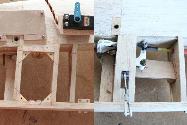
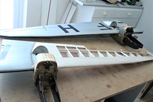
As I can't do any more with the engine until the new rings arrive, I thought I'd start to strip the covering from the outer wings. Here's what a covered and and uncovered wing looks like. The complicated bellcrank arrangement was to drive both upper and lower alierons from a servo mounted in the outer engine nacelle. Installing bellcranks like this seems laughable now but was a common method of connecting a servo to a control surface in the mid 90s. Small servos installed in the same location on the upper and lower wings should be a fairly simple job.
More by luck than foresight, the hinges have removeable pins so detaching the aileron was straightforward.
-
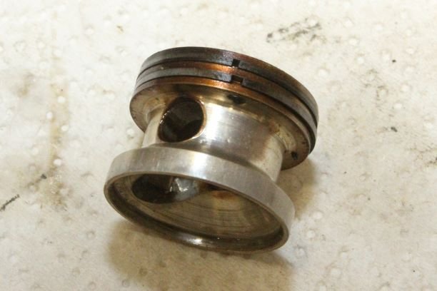
The removed piston shows signs of gasses passing by the rings. The upper ring looks to have a smaller gap than the lower. In discussing with Jon at Laser Engines, he suggests that the ring has lost some of its outward spring force and that a very fast run on a small prop may help rejuvenate it.
I've now tried this and indeed the compression is now much improved, unfortunately I couldn't get the engine to lean out properly, it was popping as if too rich but screwing in the main needle would make the engine cut out without getting rid of the 8 stroking, so the mystery continues.
-
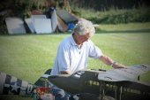
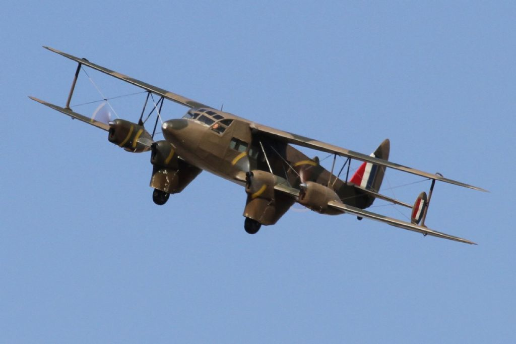
I’m running out of storage space. As much as I like building (and dislike repairing) the logical solution to not being able to fit another largish model into my shed, was to refurbish a seldom used one that was already in there. I’ve convinced myself that a restoration project is more interesting than repairs so with the completion of a little Aeronca Sedan (it won’t take up much space, honest) the way has been paved to bring my DH86 Express airliner up to date. Hopefully to sustain me will be the prospect of an attractive new colour scheme, but more of this later.

The model was built in 1995/6 and whilst not flown an awful lot in that time, has logged 102 flights without any major damage. Its powered by 4 small Lasers, unfortunately glow fuel seepage and the years have taken their toll as some of the wood joints are failing, the covering (Solartex) coming away and the paint softening. In the 1990s I didn’t know of a genuinely fuel-proof paint, I would typically use modelling enamels overcoated with a clear ‘fuel-proofer’ which of course wasn’t.
On a flight in 2013 it had a double engine failure on one side and the best I could do was hold the wings as level as possible until it flopped into a muddy field adjacent to the strip. The abrupt halt bent the undercarriage, sprung the wing joiners and pulled out some rigging. I did some hasty repairs to enable it to keep flying but they were more temporary than permanent and although it had 14 further flights, I was not really happy with the structural integrity, especially as a couple of rigging anchors pulled out on disassembly after a flying session, consequently it hasn’t flown since 2015.
In truth, I’ve been saying to myself for years that the model really needed a birthday. It has ailerons on the upper and lower wings but only a servo in each lower wing driving the upper aileron via a hidden bellcrank and pushrod arrangement. This was never ideal as each upper aileron only had half the movement of the lower one. Servos have become so much cheaper, smaller and powerful in the intervening 25 years so this time it will be one servo per aileron. The original 35MHz Futaba receiver was replaced quite a few ago when I converted to Weatronic equipment, but with the demise of that company I’ve reconverted to Futaba, so again it will be an opportunity to fit an up to date 2.4 receiver, or perhaps two, renew the servo wiring and battery supplies.
The model was designed with the rigging as a functional requirement needed to hold the detachable outer sections of the wings rigidly. Some of the anchor points probably weren’t up to the strain imposed on them as I’ve had to reglue them; not a particularly successful job with them being buried in the wings. Now when all the covering is stripped off there will be the opportunity to strengthen the anchorages.
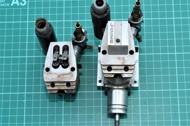
The engines, while old and not supported by Laser Engines any more, have only been in this model so should not be at the end of their lives through wear alone. The first job is to remove them from the model, clean the carbs, make sure the bearings were free and spinning easily in fresh oil, reset the tappets, replace the glow plugs and check that they would still run ok. I had told myself that if the engines were not showing their usual zest and reliability then there wouldn’t be much point in continuing with the refurbishment. Only one engine has been run so far and its well down on compression, so that must be remedied if possible.
The start of the restoration is in proving the engines. The outer wings have been given attention first simply as these were the easiest to extract from the shed.
One Laser 50 has been disassembled and as hoped there doesn't appear to be much wear apparent.
The loss of compression looks to be a badly passing exhaust valve. To test, fuel was poured into the inlet and exhaust ports. While the inlet held fine, fuel quickly appeared on the other side of the exhaust valve.
The problem now is going to be removing the collets in order to lap in the exhaust valve. I think I'm going to have to devise a better method of pressing down the valve spring retainer than fingers alone. Removing the collets will be one thing, getting them back will be another. My greatest fear here is losing a collet as that will jeopardise the whole project. Does anyone know if valve spring compressors this small are available?
I managed to remove the valve, lap the seats and refit without loss of a a collet, it wouldn't have been successful without the plastic bag trick as the second collet sprung a few times. With my clumsy and aging hands trying to refit a valve in a 50 size engine was no easy task.
The removed valve shows dirty faces and a pitted seat
A few minutes with some fine grinding paste followed up with Autosol polish and its starting to look better
A re-test by pouring fuel into the exhaust port showed the seal is now good but on reassembly the compression is still down when compared with the other engine. Thinking that I had found the problem, I didn't give a close inspection of the rings, a disassembly is again required.
-
Pleased to hear that the vaccines are filtering through, though unless someone has their own private flying field, I doubt anyone is or will be for a while, enjoying any flying just now.
If you can't incorporate throttle mixing, the other simple thing you can do is to accelerate slowly, not holding the model at full throttle and then letting go. Getting the airflow over the fin and rudder with the least amount of prop-wash will help in combatting the swing.
If the model always wants to swing in the same direction (probably left) then you could also apply some right rudder trim before starting the run and take it out once in the air.
-
Having completed a DH84, I'm naturally interested in the aeroplane and in browsing the web for relevant information, I spotted this thread.
The previous post on the subject was over two years ago, however to reply and hopefully offer some help on how to overcome take-off swing with a twin (or multi) you could try mixing rudder with throttle. I've only tried it with i/c power but I believe there's no reason why it should not work with electric motors provided each motor has its own speed controller.
Taking a twin as an example, the principle is to set up throttle on two separate channels, then make each one a slave to the rudder. By reducing the slave output to say 10% and with it being positive on one channel and negative on the other, the result is for an individual throttle servo to advance a small amount in accord with the direction of rudder movement. So, for example the left motor will advance with right rudder and vice versa, if the rudder is left at the neutral position, then both throttles open together as normal.
If the radio allows, a master switch could be incorporated to inhibit the mixing once airborne, though in practice I've found the servo movement at the top end to have inconsequential effect on motor revs.
The amount of engine differential needed is minimal and only required until sufficient speed has been built up for the fin/rudder to do its job. I've used this method on 3 models now and found its very effective in being able to maintain the desired straight line.... it especially helps with taxing.
-
Here is the line-up of the traders and exhibitors who are attending Rougham.
Adfa Models
All Steamed Up
Al's Hobbies
AMET Services
Balsacabin
Belair
Bottlecraft
Bucks Composites
BMFACRC Models
Dave Crabtree Eng.
Falcon Aviation
Fuels & Things
G Force R/C
Hawk Graphics
Hobbyking
Horizon Hobby
Inwood Models
LMA Stand
Merlin Innovations
MWM Warbirds
NexusPeak Tools
Perfect Pilots
Powerplus Batteries
Prop GuyRapid Models
RC Hobby Mantra
SLEC
Tooley's RC Toys
Torque ModelsVulcan to the Skies
If anyone would like us to set up a Bring-and-Buy area, we can do this, but would like to know before hand the likely numbers. This would be an excellent way of recycling your winter clutter (modelling items only). The charge would be £10 cash on the day, with the proceeds going to the Vulcan to the Sky trust.
The area would be set-up at the entrance to the flying area so would be in the path of all visitors going to and from their cars.
If you are interested in having a Bring-and Buy stand, please post an indication here.
ThanksEdited By Golf on 20/04/2013 06:39:39
-
-
The article on the model Sopwith Camel was interesting, if only it could have been a bit longer - I felt a bit cheated when it suddenly finished! The most intriguing article for me was the one from Dave Roberts on the handling of the full size Camel. It was well written, informative and presented in what was for me a captivating style - well done.
-
Martin,I have now built three twins and four multis, one of the twins and one of the multis had a gyro on the rudder and I don't think I could discern any difference between those and the non gyro equipped models when an engine died - they would all roll, the rate seemingly proportional to the amount of throttle opening. The recovery method has always been to bring the power right back until alierons could hold off the roll, re-trim the rudder and then land as soon as possible. I have not flown a model with a gyro on ailerons but the one I'm building now will have that set-up so it will be interesting to see how it faresHopefully I will be able to report that it works fine - but then I don't intend to suffer any more engine failures!
-
Martin,There are two points here - the model being close to the stall at the point of engine failure and the model being well above the stall and suffering the same mishap. If near the stall then attempting to pick up with aileron may provoke the stall anyway, so you are correct that there may be nothing to gain.However lets hope that most people are not generally mushing along asking for trouble but rather an engine cuts and the model immediately rolls. In those first couple of seconds while you're trying to figure out what has happened, and more importantly which way its rolled, because it can often be confusing, stabilising the wings may save the day. Yes the model is going to slow down and it will yaw to some degree (depending upon fin/rudder authority, speed and asymetric thrust) which will only increase the speed decay, but in my experience the roll rate is more dramatic and disorientating than the yaw, so attempting to reduce that roll rate until the brain and fingers are working in harmony again could make the difference between getiing down in one piece and rekitting!
-
If the purpose is to try to maintain straight and level flight, a gyro operating on ailerons will probably be more effective than on the rudder(s). My experience is that with one engine dying (on high power) the model will roll very quickly. A gyro may still not be the complete answer because if the rolling force is greater with one engine out than the ailerons can counteract, the model is going to roll anyway. The solution is to chop or at least reduce the power of the running engine(s) and try to maintain flying speed. This of course can be at odds with the instincts when trying to make it back to the patch!
The most problematical time is when at low speed and high power - takeoff or low circuits for instance, but at least you may be able to quickly recognise which engine has cut and take corrective actions. What seem to contribute to the desmise of a lot of twins and multis is being some distance away when the engine cuts and not being able to ascertain if the unexpected roll is to the left or right. Still the best course of action is to reduce the power, its better to descend into the groung upright and flat than in a spiral dive!As regards engine settings - set-up each motor as if it were in a single engined model ie, make sure each engine is running happily just as you would with a single, it doesn't matter if there are a few hundred revs difference at full throttle, but a sudden difference of 7000 revs is another story! Do not be tempted to tune one engine to match the other, this action is bound to lead to one of them not running at optimum. A slight difference in revs may want to pull the aircraft off line during the start of the take off run but if the engines are opened slowly the effect will be minimal and once rudder authority is gained the power can be advanced to full and a straight takeoff achieved.Twins and multis are great fun, you just need to be self disciplined in ensuring the engine, plumbing, fuel, plugs etc are spot on.All of this gets away from the original question as to the effectiveness of a gyro in twins but perhaps shows that a gyro can't remedy another cause. A gyro will help to stabilise twitchiness about an axis but the heart of the problem is in making sure the engines are preforming satisfactorily in the first place.Hope this helps -
Perhaps the Chinese thought it a mere detail to impersonate a Chilton, here's what G-AESZ actually looks like.

-
Gregg, You're possibly thinking of Derek Martin's Heston Pheonix, flown at many of the shows. There's a picture of it on the LMA website under 'Gallery' 'Commercial'. It's scratch built and to a particularly high standard, I believe it was completed about 4 years ago.
Derek is a member (Chairman) of the Rolls Royce Hucknall club., try contacting him through that club for more information on how he did it
Regards
-
Mick Henderson's DH9 is a tremendous achievement and I congratulate Mick for his skill and RCM&E for securing the rights to the article production. It is a stunning model incorporating many novel features and techniques. Models like this only come along once in a blue moon, so I'm surprised, and a bit dismayed, that it warranted no more editorial space (just 4 pages) than the Ultrafly ARTF foamie on page 116.
The article could have covered, with photographs, how the novel featured alluded to, were produced. The beautifully crafted DH9, in its accurate and surprisingly colourful finish, would also have made a stunning cover shot instead of the moulded P-38 which took pride of place (and 5 pages of editorial space) There was no contest as far as I'm concerned.......................I just don't understand.
-
David,
I would like you to continue with attending and reporting on shows. It doesn't of course have to be only those where the LMA members are presenting and flying their models, though clearly because their models are attractive to the public then these are the most known and attended shows; pictures of the models appear in the magazines from other contributors anyway. I would gladly read reports from the tiniest of shows - provided the models held something of interest to report, unfortunately for me that doesn't include the average ARTF that can be seen at any club field An enthusiastic reporter could write reams on how skillfully the box was opened, unaided, without damaging the contents but I think a modelling magazine should be able to impart more wisdom than that!
I cannot get to all the shows and I suspect neither can most of those flyers who try to display their models at events. Its also probably the case that most of the readership can't visit them all, so at any show there will always be something different on which to report.
I am inspired by some of the models that are built, especially those one-offs that started from a blank sheet of paper, so any information that can be gleaned and passed on us subscribers and insatiable modellers, would be welcome. I especially like to see the detail, so crisp close-ups of the model on the ground please, the pictures don't have to always show the model airborne, where of course most of the detail becomes just a speck.
Whatever model you home in on, why not conduct a short interview with the builder/flyer asking perhaps what he found attractive about this particular model? what peculiarities did it have during the building stage, or the test flying? Anything special about the construction or finishing? None of this has to be lengthy but it would add a bit more spice and perhaps demonstrate that no matter how many shows are visited there is always something different and new.
Keep up the good work
Chessiegolf
-
I was heartened to see in the 'Special' that there were three articles on built up models including the free plan of what looks to be a nice model from Tony Nijhuis and a write-up of a mouth watering engine, the OS IL300 - made a worthwhile read instead of yet another cloned .40 2-stroke . Peter Lowe's article on the Bristol Fighter emphasised a number of times the satisfaction to be gained from buildling. Good for you RCM&E for attempting to show that modelling can be much more than opening a box today and flying tomorrow.
An excellent magazine with quite a few interesting detailed articles, especially Alex Whittaker's amusing trip down memory lane. My only gripe was the waste, in my opinion, of 4 valuable pages describing a slot together, profile, 18" span SE5 - oh well, from small beginnings...................... as they say.
-
Well, it seems as if the problem is resolved. Tony KNOWS he can do better, a lot better, and has the experience on which to base that statement. As there really isn't a closed shop it would be remiss of him not to volunteer for next year's event, along with anyone else who KNOWS they can do better - if those who can do better don't volunteer, they can hardly complain when we are presented with the best of those that do!
I look forward to a fresh voice at next years Nats. Oh, and as its bad form to get people's names wrong, the commentator was (is) Colin Hammond. I must admit that his Kentish accent doesn't fall as easily on the ear as the polished voice of Dave Bishop and his knowledge of aeroplanes may not be as comprehensive, but the chap is trying to fill a void when others won't step forward......he shouldn't be castigated for that.
-
It sounds on the face of it as though Tony Jones would make an excellent commentator and I'm sure the BMFA would welcome his gesture of volunteering, it is certainly not a closed shop. Don't forget though that the commentator has to have some kind of track record and must also supply all the equipment necessary. 'Fees' usually run to nothing more than travel expenses.
The reason that LMA members are to the fore on the display line is because they have volunteered, anyone who is competent can volunteer but you have to accept that, on the display line, people generally want to see something just a little different from everyday 'club' models. The volunteers will get nothing in return except the satisfaction that they have tried to entertain the public.
It would of course be possible to fly trainers and show people that this is the way to get started, not on the slippery jets they are currently admiring and aspiring to, I fear though that the display line wouldn't hold interest for two seconds!
-
Brian,
A short length of plastic tubing, the type used for air retracts is suitable, pushed over the brass tube and lead to a remote schraeder valve will provide the necesary connection for inflating the tyre. These bits are not provided with each set, presumably to keep the costs down but are simple to acquire and make up.
My experience is that, having inflated a tyre, the pressure lasts no time at all, so better to make sure that the wheels will support the weight of the model without having to rely on pressure in the tyres.


Site Problems?
in Report A Problem
Posted
Can someone explain please, how to insert a picture between two paragraphs. I can see that its possible from earlier posts, but if I add a picture, it always appears at the end of the text.