

.jpg.378e4931e923c1d2b3fac8993b2cd321.jpg)
Peter Garsden
-
Posts
4,008 -
Joined
-
Last visited
-
Days Won
3
Content Type
Profiles
Forums
Blogs
Gallery
Calendar
Downloads
Posts posted by Peter Garsden
-
-

The rear 2mm top sheeting is trickier to fit as one has to work round the protruding elevator snake outer, chamfer the rear to fit round the rear of the fin and the upper join to the fin. The sheeting also has to be curved to fit both vertically and horizontally.
This time, instead of ammonia, I used steam which is much better for shaping the balsa. Marigolds have to be worn not only because it makes me look sweet and submissive, but also to avoid burns. I then held it in position with rubber bands befor applying glue.
The instructions recommend cyano for the bottom edge before then applying glue (aliphatic resin for me) to the upper surfaces. One still has to use pins, such are the curve parameters.
I had to use lightweight filler round the elevator snake, and the bottom join to the lower sheet sides. No matter how I tried, I could not get a fit all the way down the sides due to the curve in every direction of the upper sheeting.
-
 1
1
-
-
This is the finished rear magnet catch for the rear of the hatch which works well. I am going to add a piece of 1.5mm ply to the top rear and screw in a small screw so that I can remove the hatch when needed, such is the power of the magnets. Probably only needed one set of magnets.
I am going to line the inside of this area with fibreglass for weight and strength - such are landings on the slope. I did this with the Spitfire which has worked very well. The fibreglass will also reinforce the edges at the top where I have already added a 2mm doubler as you can see in the above photograph.
-
On 19/06/2025 at 07:23, Colin Low 2 said:
Following this one with interest. I did a similar colour scheme a few years ago during a 'Covid' build.
Looks amazing Colin. I only hope mine is half as good when finished. Questions:-
1. What colour green did you use
2. How did you do the panel lines and staining?
3. What font did you use for the lettering?
I use post it notes, and have recently bought some ink called "Smoke" which I am planning to use.
-
Anyway back to the thread, albeit thank you for your contributions, guys. I thought I would run through how I have progressed the hatch, which I had spot cyano'd into position whilst I profiled the shape of the top decking. I will use magnets at the rear and two pieces of snake inner at the front.
Firstly, I used this Dremel tool to make a hole in the rear balsa hatch. I first made a pilot hole with a cone-shaped attachment and finished it off with this. I then glued one half of the magnet into the hole with epoxy. I have tried cyano but it is not strong enough to hold the pull of the neodymium magnet. I roughed up the gluing surfaces first with a metal file.
I had to glue one magnet at a time because if not, one magnet would be attracted by the other. Even so, the second one was tricky. I had to tape it down while the glue set.
Next - marking where the hole in the opposite surface should be. I covered the end in red paint generously and then pressed it up against the opposite surface.
-
1
-
-
Front top decking was cut to size as per the plan and left slightly over at the front and top. First of all I glued the bottom of the sheeting to the fuselage sides with cyano before tempting it to roll over the formers.
i used ammonia to help with the bend. This kit is quite old and the sheeting has gone slightly hard, so it needs a bit of encouragement. It still needed some encouragement when glued with pins to make sure it is stuck all through the glue joints. I used an old knife to spread the glue
-
1
-
-
Slowly slowly catch a monkey. Fin on - not a lot of purchase to mount this. It wasn't quite long enough so I inserted a 3mm packing piece as you can see. It will be reinforced with the side sheeting when it goes on. I ummed and awed about installing a rudder. I usually do because i like it for landing and stall turns but not decided yet. It I do it will be closed loop I think.
The outer for the elevator snake is glued in having been roughed up near the joints.
-
As this ME109 is intended for IC Power there is no provision on the plan for a hatch, so I had to think how to create one, and I plumbed for something between F2 and F3. Don't do this if you make the hatch. The way to do it is only apply glue between F2 and F3, glue it in position then apply a saw to the cut as shown. As I sawed it off first, I have had to reinstall it using spots of super glue so I can remove it later.
What you can see, however, is the piece of 5mm square applied to F2 so as to provide a platform for the hatch. I am going to apply magnets to the back and 2 plastic tubes to the front into holes in the block balsa cowl. I am going to put a liner of 1/32 ply to provide a secure outliner for the two holes.
-
2
-
-
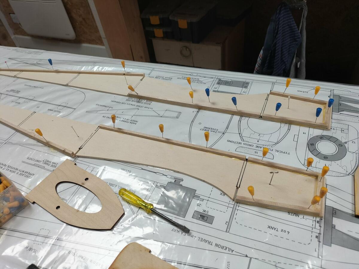
Slight progress in that the formers were glued to one side making sure that they were at right angles using engineering squares, then the other side place on top, clamped and glued using aliphatic resin - Titebond being the cheapest
Then I pinched the tail together over the plan, having carved the sides to a point, and glued in position whilst holding it with a rubber band and clamps.
Before doing this I made sure that F2 was fret sawed out square to take the battery box made from lite ply and cyanoed together again using engineering squares to ensure that the sides were at right angles to each other.
I am going to fibreglass reinforce the front of the fuselage for strength and less weight being needed to balance up. The battery will be up against F1 or rather the front wall of the battery box which will be glued to F1. So the battery box will go in last once the surrounding walls consisting of 1/2" balsa are glued in place to form the cowl for the engine if one was to be fitted, which it isn't as this is a slope soarer.
-
2
-
 1
1
-
-
As this will be a PSS Slope Soarer no need for a motor or space for a LIPO battery, but will need a battery box for the 4 Cell Nimh Enloop I have waiting. I found some old light ply of 3mm and made up a battery box which will pass through F2 and be glued to F1. I used Engineer's squares to make sure the sides were at right angles and used cyano.
The existing F2 has a hole to take the petrol tank, this kit being an IC Version, so I marked it out to 40mm to take the box which I will cut out with the fret saw later.
I will jam the battery in with foam rubber eventually.
-
Fuselage
Well the wings didn't take long - simples and quick, so on with the fuselage. First job is to add the 5mm square longerons to each fuselage side - making sure that one produces a left and right half!
I placed the formers in temporarily to produce a good tight fit for when they are glued in later.
-
Wings now joined with fibreglass bandage supplied with the kit (not a lot to spare!) I have always used finishing resin to soak into the bandage before but this time tried PVA as recommended. Presumably this is just as good? Doesn't seem as hard or rigid as resin? When finished the whole wing will have resin & 25g cloth applied with a roller so I guess it doesn't really matter
-
I didn't photograph the attachment of the aileron linkage. I am going to use two small 9 gram servos in the wing for ailerons rather than one big servo as I want to dial in spoilerons and provide for thermal trim if necessary.
The tube that takes the linkage is sunk into the trailing edge. I made the groove with this Permagrit Needle File which is worth its weight in gold. I used some vaseline and was very careful not to put too much resin on the joint. I also made sure that I bent over the linkage AFTER inserting the tube. One also has to make sure you have a right and left hand linkage. Make sure you rough up the plastic tube before gluing to provide purchase.
This shows the left hand wing, the aileron having been bevelled, grooved for the mylar hinges (also roughed up before attaching so as to provide purchase for the hinge glue when it is used - though do not glue yet - await covering and paint later.
-
2
-
-
Now the process of sanding down and planing the leading and trailing edges as well as the tip blocks. I always used the tried and tested method invented by Andy Blackburn whereby masking tape is place on the edge to be planed. When you are getting close to the mark the masking tape rips rather than taking chunks out of the veneer. You then finish off with a sanding bar. Mine was invented by Chris Williams and is a long piece of 15 inch x 2 inch wide scrap 1/4 inch balsa with 80 grit taped on one side and 120 grit on the other. Brilliant for this job as you can reach right over the wing in one sweep.
-
2
-
-
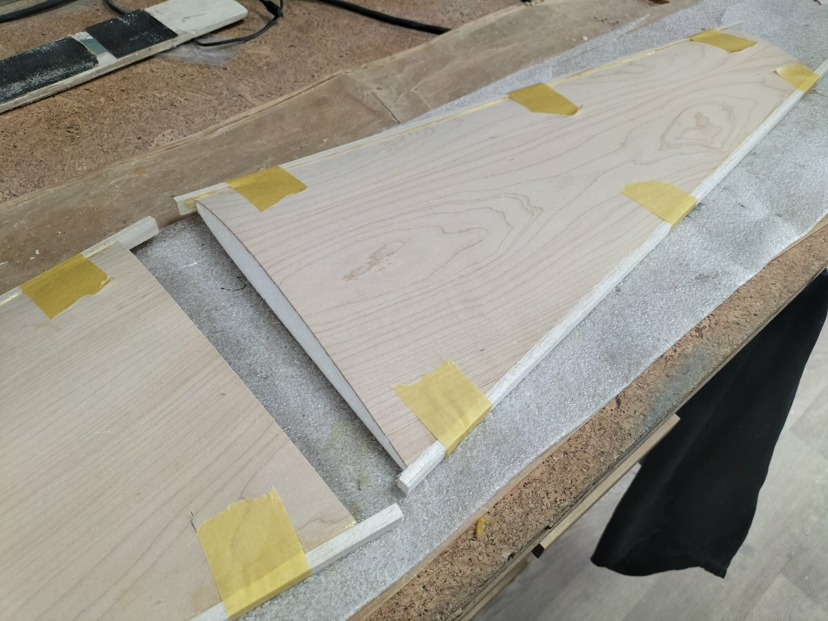
First easy step is to glue on the precut pre formed leading and trailing edges. This time I used Frog Tape which sticks so much better if more expensive. Used waterproof Titebond. Cheaper than modelling aliphatic I would say. Time for a snooze. You have to be careful to put the correct strip the right way up on the right edge
-
2
-
-
I wasn't sure how old the kit was but everything looks in tip top condition and almost new. I ironed the plan flat and and am looking forward to kicking off
The veneer on the wings looks top quality. First job is to attach the leading and trailing edges, which come already preformed in section - luxury
-
3
-
-
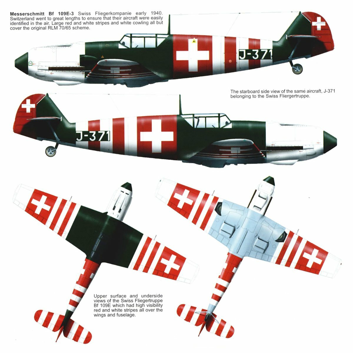
You will be only too familiar with the Swap Meet scenario of "I won't bring any cash because I don't need any more models, and I definitely won't buy anything today." I went to last year's Phoenix Model Aircraft Club swapmeet and saw an untouched kit of a ME109 Funfighter and just had to have it. I had my phone with me so paid the chap using BACS there and then. He wanted £60 which was a reasonable price so I didn't haggle.
It sat in the queue and has just come to the top of the pile. This year I booked a table and sold me A4 Skyhawk which has had a lot of air time, thus making way for it. I have a Spitfire which flies so well - fast and furious.
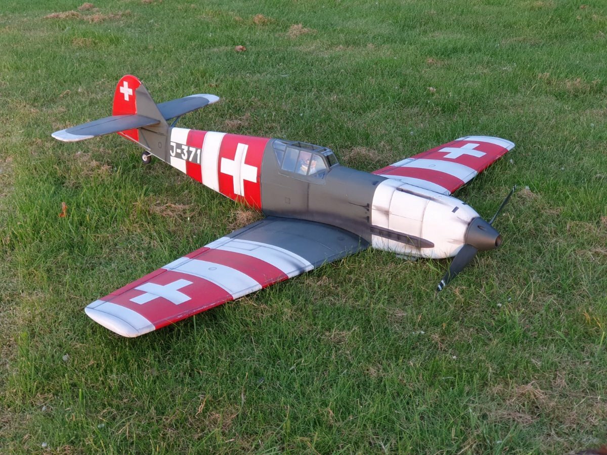
This kit is the IC version but I will convert it to a PSS glider. I am not going to follow the conventional colour scheme and will choose something different. I fancy the Swiss Airforce variant
-
5
-
-
Sorry not updated the flying of this pocket rocket, which took place a couple of weeks ago up at Elkstone, the Easterly Slope used by Leek and Moorland Model Gliding Association. I had previously tried to fly it at Back of Roaches but there was not enough wind, so I had dialled in too much reflex.
Colin has cleverly incorporated some reflex into the wing section he uses. Anyway the wind was about 20mph and the lift good. I had set up control movements as per Colin's detailed instructions - about 5mm for elevator and 7/8mm for ailerons. It doesn't need much as it flies at such speed.
I had to land quickly to dial out the reflex and relaunch. It immediately got into the groove and sped round the sky at some lick. Rolls were quick but not too quick. It does lose height in the turn but not much. I needed some right trim but found my trim switch was stuck. I therefore put too much left trim on, which would not correct itself so I landed as I had to fly with some right stick correction. When I got home I discovered the problem was super glue. Fortunately, with a very small screwdriver, I was able to remove it, so another flight is awaited.
This is a very fast reasonably priced flying wing which will provide hours of fun.
-
2
-
1
-
-
Well, that did not take long. Jobs to finalise have been
- Make a piece of ballast as recommended by Colin - see below
- Use a mini receiver to site behind the wing out of the way of the ballast.
- Make up some leads to attach to the receiver and meet up with the two elevon plugs
- Balance - the cg is 31 to 37mm from Leading Edge, so I made up a plasticine plug as a mould inside the nose, push it into sand surrounded by two layers of tin foil one of which remained in the sand, melted some lead in a tin and poured it in. Beware however that you lose about 10% as oxide so weigh afterwards.
- Glue the weight into the nose using a syringe and nozzle to get the glue in the right place
- Make up some extra white smaller decals with my vinyl printer - Fonts are Bauhaus 93 Italice for Wotz@ and Arial Rounded for XL - and put them on the fin
So ready to mainden hopefully on Saturday
The ballast weighs 186 grams and is 50mm long out of 21mm copper piper. The hole takes the front wing bolt which holds it in position.
Looking good?
Can't do without the usual WIckes Radiator insulation carrier bag, can we? Keeps it safe from dings and UV Light
-
1
-
Have been busy with the airbrush (new one with big nozzle for large areas by Sparmax - really good coverage - https://airbrushes.com/product_info.php?cPath=400_403_1_146&products_id=22739 I have bought some airbrush mixed red and black from our local Arts Store, which cover really well. Then for the top of the wing and the canopy, I have used my B&Q mixed bright green which I have got lots of with some masking - turned out very well considering
Also Colin provides a decal which is very appropriate. I applied from clear removal film so that the letters stick to it, come off the backing and can be laid down in position. One can use Masking Tape but it isn't as good.
And
-
1
-
-
Whilst I wait for the copper piping for the ballast, to arrive, and the micro receiver, on with the canopy
First of all the front catch. Colin says just glue it in with epoxy. I tried that and it pinged off when I tried to place the rear magnet in position, so I reverted to my initial plan of covering it in 2 layers of 150g fibreglass cloth
Then the rear magnet glued into position in a recess already drilled by Colin - important to make sure that that one does not try to match 2 North Pole Magnets.
Piece of masking tape to prevent the structure sticking to the bottom magnet when epoxied into position.
Finally, epoxy glue mixed with some fibreglass dust, applied to the tope of the top magnet and the underneath of the canopy, and secured into place to dry with masking tape.
-
1
-
-
Next step is to glue the supports Colin supplies cut down to size. A syringe is the only way to direct the right amount of glue and not foul the cover. I used laminating epoxy again as it is thinner than glue.
-
22 hours ago, Konrad said:
Few F3F guys are mounting servos as shown. Besides F3F wings are constructed very differently.
Can I ask why you abandoned the servo tray? Does Colin concur that the servo cup is rigid enough as to not allow distortion of the top skin should one try to pry free the servo?
I glued a disc of fibreglass on top of the foam then the cup. It'll be fine. It's a flying wing not an F3F racer, with respect of course. Didn't use the servo tray because I couldn't think of a good way of securing it without buying your attachment.
-
Well I decided to use laminating epoxy to glue the servos into the base of the servo cup, having roughed it up first. I would not use normal epoxy. If one needs to remove the servo a piece of metal to support a screw driver to prise the servo out. To replace it then one just spreads a thin layer of laminating epoxy again. F3F boys use this method. it stops any movement.
You can see the epoxy which is mixed with micro balloons. No slop at all and the elevons move perfectly. I have, however, ordered a micro receiver which I will install in the fuselage behind the trailing edge. This leaves room for the ballast copper pipe to be attached to the forward most wing bolt.
You can see how I have filed down both the clevis and the control horn. I have marked positions for the servo lid support block which will take the screws for the servo hatch
This is the other side. I have memories of it being really difficult to line up the screws with the block, so this time I thought I would fit them to the lid, then glue the whole thing in with epoxy to the underneath. In this photo you can see that I roughed up the wrong side of the servo!
Hopefully, if I simply apply epoxy to the underneath of the blocks not the sides, the lid will not stick. Once the lid is released, I can then apply glue to the sides of the blocks.
-
1
-
-
On 05/02/2025 at 14:48, Konrad said:
Good call Konrad. The method you show is that suggested by Jonathan Wells on the Magnus. When I tried it, I had trouble avoiding stripping the thread on the plastic servo horn, and not heating the control rod too much so that it snaps in the bend. I had about 4 goes at it but it has stayed put. So I think I will go for a clevis at both ends of the control rod, the servo end heavily filed back to as not to foul the servo hub.
I have used this sytem before. What I am doing is using my 2mm die to make a thread on both ends of the control rod. I couldn't get the clevises to wind onto the 2mm studding I have left. I think the thread is damaged. So I now have a control rod with threading at each end, and that seems to work.
First of all, however, I needed to make a hole to exit the control rod from the servo hold cup, and from the other side through the slot I have made. For this I used a 3mm tungsten carbide round file
And the other side
-
2
-


Messerschmitt ME109 (Cambrian Funfighter)
in PSS Build Blogs
Posted
As usual I reinforced the front chamber between F2 and F3 with fibreglass cloth and resin. It provides extra strength in the event of a hard slope arrival (highly likely). It also means less lead in the spinner.
I did one surface at a time using gravity to ensure it stayed flat.
Next job is the cowl which is designed for ic engines. I have made an extra piece of 1/2 inch to cover up the gap designed for the cylinder head to exit. I am going to line it with glass cloth as well