.jpg.378e4931e923c1d2b3fac8993b2cd321.jpg)
Peter Garsden
-
Posts
3,917 -
Joined
-
Last visited
-
Days Won
3
Content Type
Profiles
Forums
Blogs
Gallery
Calendar
Downloads
Everything posted by Peter Garsden
-

From the album: Petrel 3.4 m Glider
-
From the album: Petrel 3.4 m Glider
-
From the album: Petrel 3.4 m Glider
-
From the album: Petrel 3.4 m Glider
-
.thumb.jpg.6e9ca6f431386c6c58ab30794f332751.jpg) Next is a dob of P38 car body filler, rubbed down to smooth.
Next is a dob of P38 car body filler, rubbed down to smooth. -
Magnus 60" Span Moulded Soarer by TJIRC
Peter Garsden replied to Peter Garsden's topic in Slope Soaring and Dynamic Soaring
Use the rods and tubes then clear tape over the joints. Fairly secure anyway so belt and braces really. Sorry only just seen this. -
From the album: Petrel 3.4 m Glider
-
I have now filled the gaps in the fairing pieces with some scrap block balsa. No need to be precious about it. Also used a cone drill to open the large holes in the fuselage side for the electrics, and rubber securing bands. Next job is to spread P38 over the top to smooth out the surface and fill in the holes such as there are. It was very difficult to fit a piece to fit which was curved in 2 axis.
-
From the album: Petrel 3.4 m Glider
-
What a fiddle this was. I tried to cut the brass box and tube to size without putting the fairing 3mm liteply support in place and, inevitably, it was too short, so I had to make another. Fortunately I had enough left over to do so. The way to do it is to feed it in oversize, the holes having been cut for the tube, and line up the fairing piece, and cyano it into place by pushing one wing on and making sure the ply fairing rib was at the right angle. Then do the same with the other side, more cyano and you end up with the wing fairing structure in the correct position. I then cut the brass box and tube to size, took the wings off, and glued the box and tube to the fuselage and fairing ribs with epoxy, which I syringed into position. The brass is slightly oversize but I will file it back. Next job is to fill the gaps either side with curved pieces of 12mm balsa, then finish off with P38.
-
From the album: Petrel 3.4 m Glider
-
From the album: Petrel 3.4 m Glider
-
The slots for the wing bearers are cut and amazingly they line up with the tailplane, so it is just a case of getting the angle with the tail correct by using an incidence meter. The wing has to sit at positive incidence to the tail at between 1.5 and 2 degrees. First one puts the meter shown here onto the tail and zero it then attach to the wing and measure 1.8 which I settled for as a half way house.
-
From the album: Petrel 3.4 m Glider
-
From the album: Petrel 3.4 m Glider
-
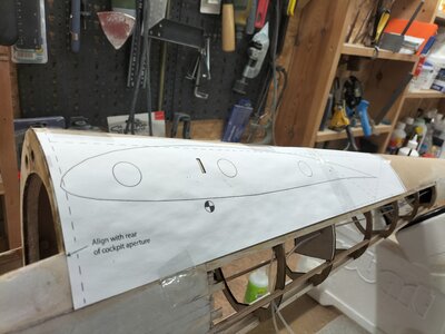
Next is the most difficult bit - marking holes for the wing joining bar which is a rectangular brass tube. One uses a template taken off the plan and lines it up with the rear of the canopy opening and the plywood join line I lined it up carefully and sellotaped it into position. Should have used masking tape which I did for the starboard side. I used a brand new scalpel blade and cut carefully.
-
Both rear plywood sections now on and closed loop tubes in place. I think that was more difficult than the top piece.
-
From the album: Petrel 3.4 m Glider
-
From the album: Petrel 3.4 m Glider
-
Spitfire by Cambrian Funfighters Electric Version
Peter Garsden replied to Peter Garsden's topic in Warbird kits
The Spitfire flew well on Saturday at Edge Top, Leek, Staffs as you can see. The wind was about 25mph and the lift good. It does need a good blow and does fly fast. All in all a success -
Spitfire by Cambrian Funfighters Electric Version
Peter Garsden replied to Peter Garsden's topic in Warbird kits
Well a bit of news - I took the completed Spitfire to the PSSA meeting at the Orme with a view to flying it on the Friday. Conditions were ideal with a 20mph wind on the tank tracks slope if slightly Westerly. I duly assembled everything. I had a switch to turn the motor off with the Failsafe set to 0%. All good so far. I switched on and went to put the model down, by mistake switched the switch off and the motor revved up to full speed - no prop on as it was set up for sloping. I couldn't stop it and had to disconnect the battery. By this time it had pulled the cowling and the motor box off the firewall. I was so annoyed. I really don't know why this happened. Al suggested it was because on Futaba Transmitters the motor reverses itself so 0% was 100%. I had weighed the model at 3.4 lbs so it would have flown fast, but none the less I was annoyed, so back in the bag it went. So I decided to make it a PSS model only, took the motor out, replaced the fibreglass cowling I had made with the original balsa cowl, balanced and weighed at 1lb less ie 2.4lbs - more like it. I took the LIPO out and put an NImh battery in its place. I had to cut away some ply to make a battery box slide in. And I bought a magnetic switch so I don't have to remove the hatch to switch it on. Finally an underneath shot showing the airbrush shading I did. I am planning to fly this, wind permitting, at the LMMGA Club PSS competition a week on Sunday - https://www.lmmga.co.uk/2011-08-18-13-54-36/277-power-scale-club-competition -
I have been doing a bit of repairing to the Spitfire and Alpha Jet following the last PSSA Meeting at the Orme, but now finished so back to the Petrel and the lower rear sheeting. Thankfully this is in 2 halves, as the bend over the bottom of the fuselage would have been a step too far. Again I used paper templates - I just cut up the previous template made for the top of the fuselage. After cutting out it needed a bit of fettling until it would fit the slightly skewed shape. The join is slightly higher up the fuselage than the top piece to stagger the join and aid strength Again the kettle without a lid, Marigolds, and a lot of steam eventually led to the ply bending to the right shape. A small piece of balsa aids the gluing area of the slim piece of tubing I bought from Hyperflight which will act as a guide for the closed loop rudder wires. To force the piece exactly into position required a lot of clamps and masking tape. Needless to say the elevator control rod has been made up and attached to the servo and lined up before I took this step. I used a piece of 5mm outer and 3mm inner carbon rod with bicycle spokes glued into each end and shrink tubing over the top.
-
From the album: Petrel 3.4 m Glider
-
From the album: Petrel 3.4 m Glider
-
From the album: Petrel 3.4 m Glider