

.jpg.378e4931e923c1d2b3fac8993b2cd321.jpg)
Peter Garsden
-
Posts
3,917 -
Joined
-
Last visited
-
Days Won
3
Content Type
Profiles
Forums
Blogs
Gallery
Calendar
Downloads
Posts posted by Peter Garsden
-
-
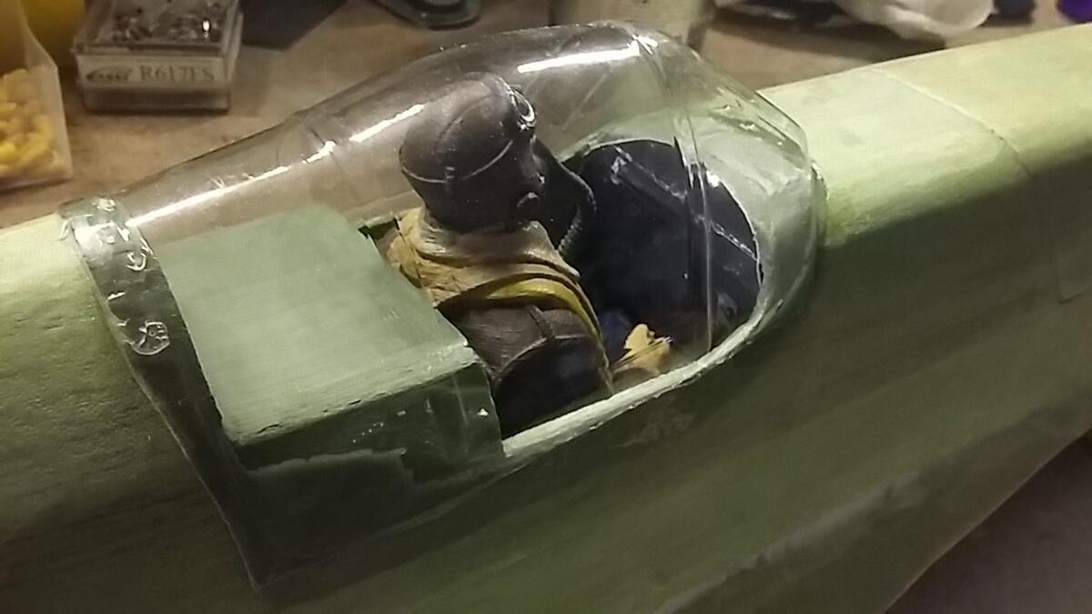
Before I start spraying on some undercoat with my new Iwata Airbrush, The canopy has to be added and Reginald, or was it Arthur, I forget.
This is cartoon scale so I usually find a cockpit layout, print it on photo paper to the right size, glue it onto some 3mm balsa and stick it in position. This is the cockpit I found

So I put this in first. Bit of a waste as you can't really see it
Reginald looks a bit bored. He just fits in - thank you again Andy Meade for him
Also cartoon scale is the position of the engine exhausts, but done so as not to have part on the removable hatch and part attached to the front of the fuselage, which would be necessary if we were to adhere to scale positioning. I used a combination of canopy glue and cyano. There is not much to adhere to
-
 2
2
-
-
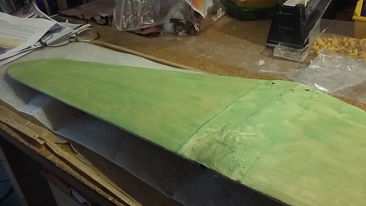
So the next job is to fill the weave of the cloth with something. Thanks to McG for telling us PSS lot about Freddie B's Secret Sauce which he swears by. I haven't tried it yet but it takes me back to the days of when you use do mix talcum powder with dope to make a creamy filler on top of tissue. Freddy is American and used it to fill foamies prior to painting. It filled the bumps and made for a smooth surface.
As I have finished this in 25 gram cloth and resin one has to fill the weave of the cloth. It is possible to do with with primer or high build primer, but it costs in primer. This method is a lot easier and produces a surface as smooth as a baby's bottom - because I used Baby Talcum Powder. Gets a thumb's up from me. So how is it made?
- Dollop of light weight filler
- Equal amount of Eze Cote of Poly C - water based resin or water based varnish would do.
- Equal amount of Talcum Powder.
- Few drops of Acrylic Paint to suit - bear in mind your eventual top coat and undercoat. I went for green because my colours are mainly olive, and grey.
- Mix it together into a paste.
- Add water if needed to get it into the consistency of double cream.
- Brush it onto the model and let it dry - only takes 20 minutes
- Sand it off with either 180 or 220 grade wet and dry. Next coat will be primer. It has filled all the gaps and the weave in the cloth.
-
1
-
One has to be careful to peel off only the peel ply and not pull the fibreglass cloth off at the same time - peel ply in one hand cloth in the other.
Once the resin is dry, one attacks it with a Permagrit file (coarse) at the edges to work through the thin cloth then it just pulls off with a neat join on the corner. Doesn't need to be overlapped.
This is the rudder for example. You have to be careful not to mark the cloth with the Sharpie marker over the wood as it can show through the covering particularly if it is a light colour. You can see I have used dots here
After filing off the edges are sharp and neat again. The slot is for my home made fibreglass horn lined with 1/32" ply each side for strength.
-
So to covering. I am going to apply 25gram fibreglass cloth with a coat of resin, then fill the weave with some Freddy's Sauce (watch this space) then paint. I use Easy Composites Laminating Resin and cloth from East Coast Fibreglass, which moulds really well to the shapes offered to it.
In order to avoid excess resin and weight I use Peel Ply over the top of the cloth which soaks up any excess and keeps the cloth close to the surfaces. After the resin dries you peel off the peel ply and use a Permagrit File to file off the excess overlap at the edges.
This shows the tools - a Jenny brush is used to apply the resin which then has to be thrown away and a discarded credit card to spread out the resin on the wing.
Important not to join the cloth mid fuselage as it will leave an edge very hard to eradicate. This drapes over each side and is sanded off underneath.
-
1
-
-
15 hours ago, leccyflyer said:
Nice work Peter - one thing though, I don't understand why you are balancing the model before it's been covered and finished?
Good point. Without asking you to read through the previous threads on this blog and Graham's build blog, in a nutshell, he had a lot of trouble getting the C of G on his model because there is very little room to insert it after the cowl goes on. The cowl is not removable to add any balancing lead, so I devised a plan to make the cowl removable, and test the C of G before covering. We will see whether the C of G remains the same after covering. I certainly hope so. I hope this makes sense.
-
 1
1
-
-
Plea for help guys. The motor exhausts have to be glued on the sides of the fuselage. The position is bang over the edges of the battery access hatch. So
- Do I glue the exhaust to the hatch and not the front fus so that the hatch will come off easily. Graham what did you do?
- I have always had 3D printed items or ABS plastic before so as these are in clear perspex presumably one uses canopy glue to attach them?
- They are printed with a border round the edge with some screw indents. Presumably one trims right up to the exhausts and glues the edge to the battery hatch? Or does one leave say 3mm all round the edge and use that as a purchase for the glue?
One could of course cut it in 2 and glue a section to each ie cowl and hatch but as the hatch opens upwards I am concerned that this might foul the opening action. Graham you will know what I am talking about.
-
Having added the fibreglass cloth to the top inside of the cowl, I had to make a few easing adjustments before gluing on the cowl permanently. I must admit I did consider making a fibreglass version which I could screw into position, the motor being quite a permanent feature but didn't do so in the end.
Next is cutting the cockpit to size and painting the inside before glassing. I never know whether it is meant to stretch so much to get it into position or not. I have some cockpit green which I am dying to use.
Can't remember if I showed you Reg, my trusty 3/4 pilot which I have painted - thank you to Andy Meade for supplying the 3D Print - but in case not here he is
-
1
-
-
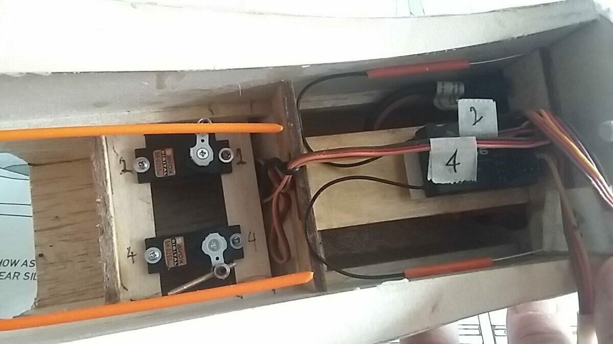
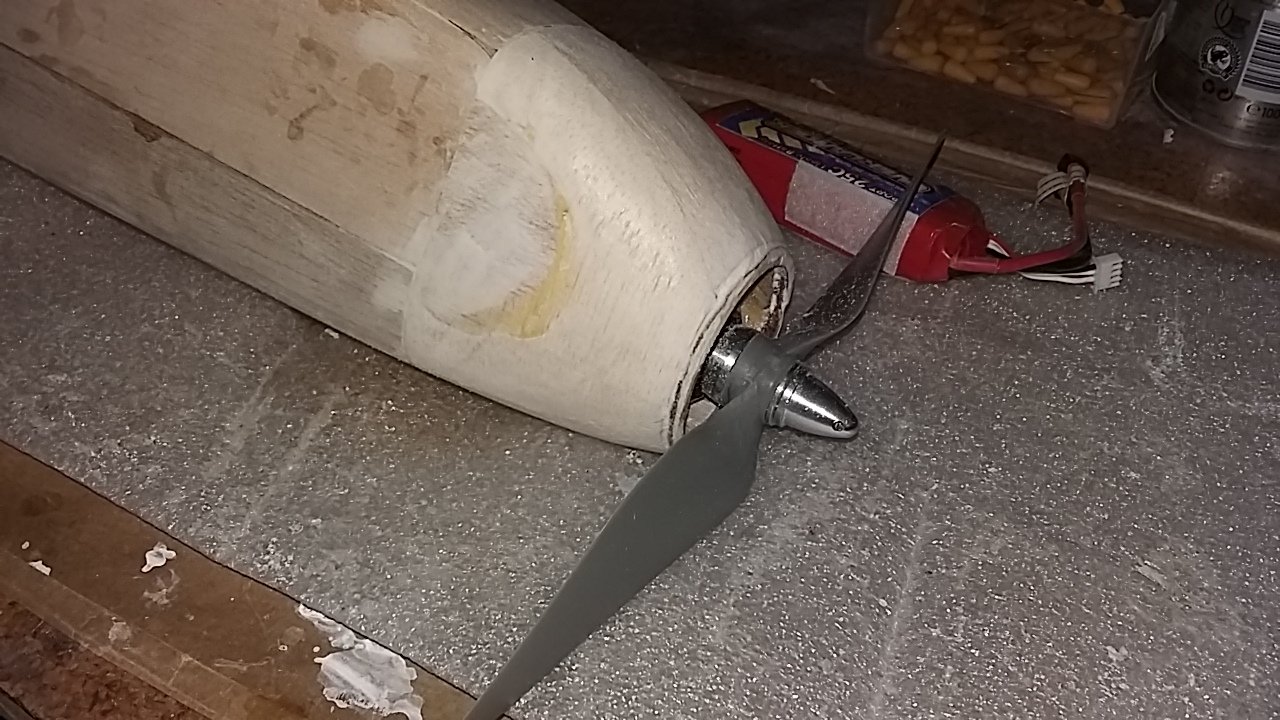
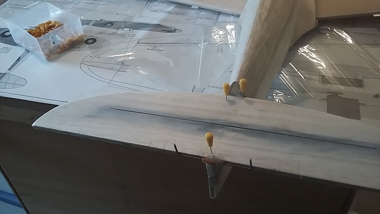
The plan was to hook up all the connections and test the C of G so that if weight was needed to the nose, I could add it before the cowl was finally glued and attached. So the first job was to intall the fuselage servos and snakes.
You can see that I have installed the servos wher stated on the plan r\ther than further forward either side of where the receiver is next to the battery hatch. I tested the C of G without the wing on and it seemed to be in roughly the correct place with the propeller and spinner attached.
I then set up the Vanessa balance machine to find out if the nose needed any weight. I needed to add a little bit, so I tapped the cowl to relieve the cyano spot glue. I then glued the lead to the bottom front of the cowl.
I left the top of the cowl unglued and not fibreglassed, so I epoxied it on, and have now wrapped fibreglass round the inside.
-
2
-
-
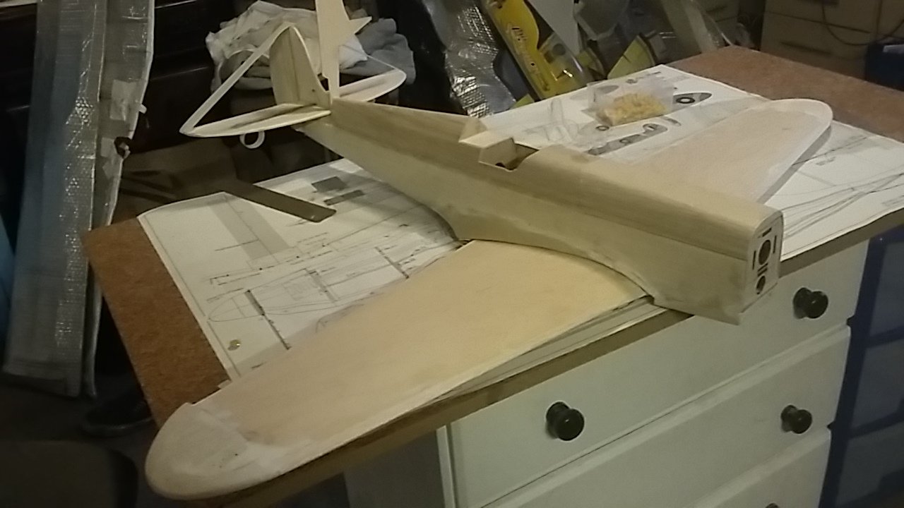
These pictures show the carved nose up to the ply nose ring at the front and the ply former in front of the wing with the propeller attached. It was not as difficult as I thought planing cross grain, the sides of the cowl.
And one can see that I have added some filler pieces of 1.5mm balsa at the sides to fill out the width.
I roughly attached all the parts and the battery. Despite previous concerns, the C of G does not seem to far away from that specified on the plan.
-
Great write up and pictures as usual Phil. Describes the weekend perfectly.
-
2
-
-
Thanks Graham, all good ideas. I plan to carve the nose to shape, install all the hardware ie control rods etc, and the battery then see how we go. I will balance it before covering and hope the balance remains the same. My ideas set out below.
I have attached the cowling at the front ready for pairing down with the plane and sandpaper and Permagrit files but with only a few spots of cyano. I have also NB, attached some masking tape to the front of the detachable top hatch so that when I use the plane it won't dig into the balsa of the already planed hatch, but just graze the surface of the masking tape.
Also note that unfortunately the side cheeks of the cowl have the grain vertical rather than horizontal. This is unfortunate because planing across the grain will be difficult if not impossible. No doubt this is done for economy of balsa cutting but not how I would have cut them out myself ie grain horizontal.
So what I am going to do is wait for the blobs of cyano to hold properly - about 9 all the way round then plane it to size. I can then take it off and once the engine is properly in place epoxy it on permanently.
I have already had a session with the transmitter, making sure that the motor is rotating in the right direction and marking the wires with coloured masking in case we have to do it again. Also to enable lead to be added is possible. I can also move the servos backwards or forwards.
As I am using the strong servo screw method to attach the motor, I don't really want to take it off again. I did think of using this as a mould and fabricating a fibreglass thin removable cowl, but I am too lazy to do that. If this breaks I might go that route (probably not)
-
Been busy but made a bit of progress. Thinking always of Graham saying it needs noseweight and the difficulty with that, I decided to make the cowling removable at least at the top to be glued in permanently once balanced later.
You can see that I have lined it with some 150gram fibreglass cloth and resin for extra strength. I have also made the ledges to attach the top blocking. I will spot glue it in place to sand it and plane it to shape. First of all I must attach the engine.
View from the front showing where the nose ring will go.
Top block a tight fit but removable to add lead and plane to shape.
-
1
-
-
Just another reason why I never win prizes at this event, so detailed, scale like and accurate is your build Chris. If my 4lb 7oz porker can fly at such a speed then your 5lb er will really motor. Probably needs a bit more wind. Just make sure the C of G is right because I thought mine was right until I checked it properly with my Vanessa Balance Cradle and I discovered it was way out to the rear. No wonder it flew like a bag of shite. Only when the C of G was right was it transformed.
-
1
-
-
Thanks Rich. I used to pin hinges the same way and I agree it is more secure. I stopped doing so, however, when, in an impact, the control surface ripped out not only the hinge but also some of the wing with the peg. Recycled waste is a good one though.
-
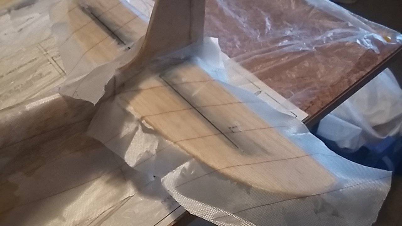
Before adding the elevators and fin, I slotted the parts for the mylar hinges. The mylar provided was glossy. One has to rough it up with a coarse file to aid with sticking it in position with hinge glue I used, which is a water based glue rather like canopy glue. J Perkins supply it.
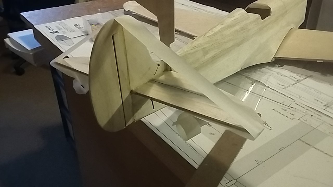
I am adding a rudder so I cut out the rudder along the marks shown on the plan.
Tricky to line up the fin accuately as it is so narrow. Because of the banana shape of the rear fuselage in horizontal plane, I had to ensure that the fin was in line with the centre line of the fuselage. This put it slightly off centre when lined up with the centre of the fuselage. Once the gaps are filled either side of the fin to blend in it will not matter.
It's beginning to look a bit like a Spitfire at last. The piece of 2mm balsa sticking up at the front of the fin is to fill the gap left in front of the fin.
-
3
-
-
The tailplane is now a lot stronger with carbon rods albeit only 2mm each top and bottom. I glad I did it. I am sure it didn't add much weight.
The instructions don't say much here but I decided to added the joiner before I glued the tailplane on. It would be very difficult to do this effectively when in situ. I added vaseline to the rods to stop them sticking, and strapped the plastic tube on with epoxy mixed with microfibres and masking tape. Before I did so, I added the elevators to make sure everything fitted and to ensure it was glued in the right position.
The wing was attached to make sure that elevator and wing lined up perfectly. Although the tail is banana shaped, pulled out of shape when the top sheeting was bent into position, the wing and tail lined up perfectly, so it was the fin that had to be glued at right angles to the tail but not the fuselage line.
-
Next is making holes and grooves in the elevators for the wing joiners. I put tape on a 1.6mm drill which is the right size, and used my pillar drill. Previously I have made holes in the trailing edge but not this time. I then used a dremmel tool to make the slot after cutting a slot with my balsa knife.
I was worried about the weakness of the stab which is just a piece of 5mm balsa. I fear it would snap so strengthened it both sides with inset 2mm rods of carbon which should not add much weight but a lot of strength.
-
This is my amendment for the hole to house the front wing dowel. I have cut out a section of the leading edge to take the block into which I have marked the angle of the hole for the wing dowel, cleared out to take a 6mm internal diameter carbon tube. I really would have preferred a brass tube, but carbon will be fine.
The beauty of this system is that the front dowel can be lined up exactly whilst the glue dries. I lined the front with selotape so that nothing stuck fast
This shows the balsa block glued in place and trimmed to shape before the illustrated piece of glass cloth is wetted into place for extra strength. Cloth both sides.
-
Thanks so much guys for your help. I know the ply mount looks fixed but it is not yet glued. I just mocked it up for the photo so you would know what I was referring to. All good suggestions. I will have a ponder and look in my spares box to see what is there. I think I favour the blind nut route though the threaded inserts look interesting. Thank you again all of you - helps a lot for a slope soarer who has not a lot of experience with power.
Graham, I am going to re-engineer the front dowel - further photos to follow. As for the motor I am using that recommended by Cambrian - the 1500KV motor I think - the Tornado Thumper 3536 with a 40A ESC and a 9x6 prop so hopefully we should be OK with a 3S 2200mah battery. I suspect, however that it may get more used as a PSS sloper. I am going to have 2 spinners - one for slope use with some lead in it, and another for power
-
1
-
-
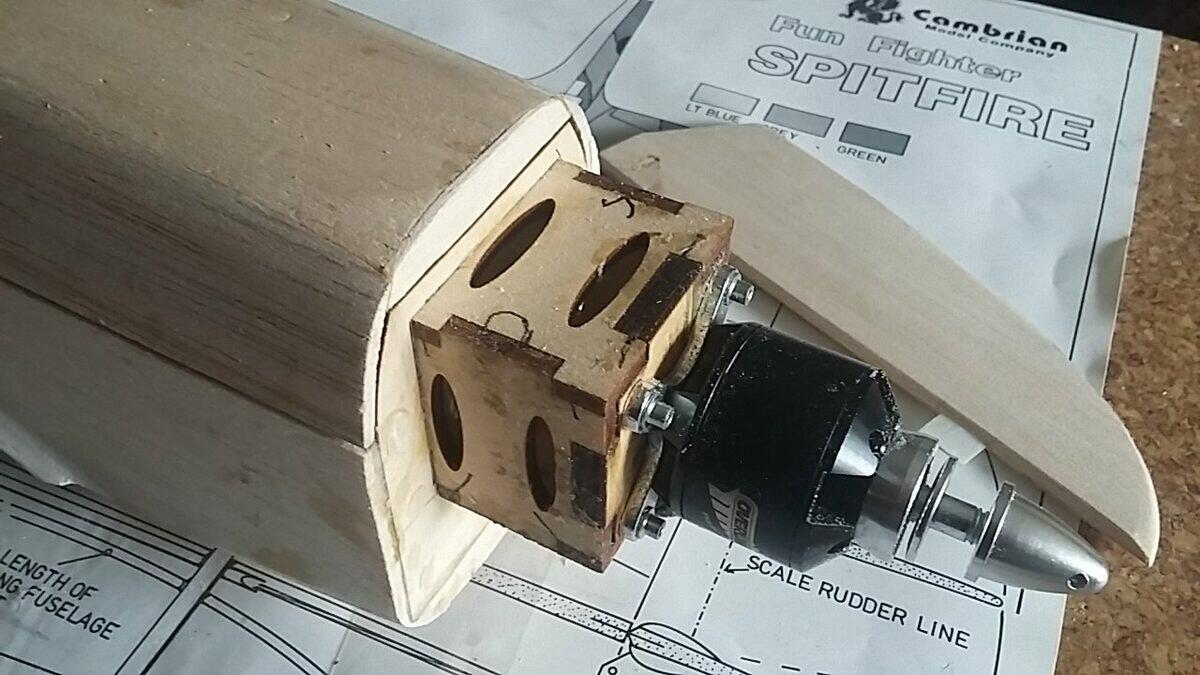
Plea for help.
There are no clear instructions on how to attach the motor to the ply box engine mount and I am a bit stumped. This is clearly a very old plan which has been adapted for electric motors. It just says assemble the box having made holes for the motor metal cross thingie to attach to it, glue up the box and attach then attach the motor.
The problem is that the box has 4 sides and a front, so how do you get access to the motor nuts and bolts if you want to remove the motor at a later stage?
Also, if the bolts pass from the outside to inside, how do you secure blind nuts to the inside and avoid them falling into the space? If the other way round, how do you get access to the head of the bolt to tighten it? Graham you have built one of these so may need some pictures of how you did it.
The cross thingie has to sit diagonally with the holes in the corners methinks.
-
I couldn't work out from the instructions if the wing profile filler should be stuck to the wing or not. I think this is right but am not sure. It was tricky to fit as parts 20 shown are at a different level to the former, so a step has to be filed into it. Epoxy did the rest!
Because the wing is slightly off to one side the aileron push rods foul the former, so I have cut a piece out of it to allow movement
-
1
-
-
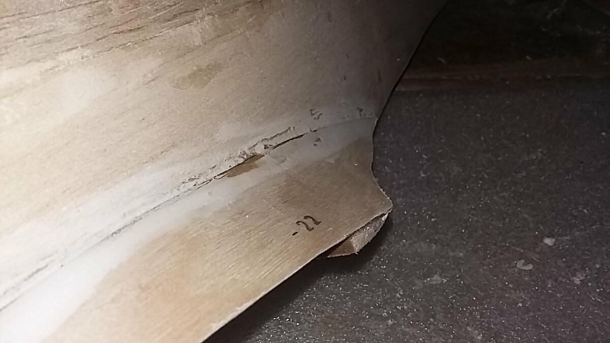
Apologies for not showing the construction of the wing fairings - always a tricky part of the build on any fuselage. The 0.4mm ply covering is good quality birch (part 22) but it is difficult to bend. I glued it on oversize then trimmed it with scissors - easy as it is so thin. I also steamed it to ease the bend. I used cyano, and cannot see any other type of of glue working - if you don't use plastic bags on your fingers you end up stuck to the fuselage! (How do I know this?).
The underneath fairing sheeting which is made of the same thickness of ply but cross grain - great idea as it bends more easily under the wing seating profile - is quite easy to apply. You cover the fuselage dowel hole and the top of the wing with Sellotape to stop it sticking, then glue it on with epoxy. Screw the wing in place and leave it to set.
-
This shows the under sheeting to the nose and the wing locating dowel, which curiously, is attached to the fuselage rather than the wing. I think this is because the hole in the wing is simply drilled into the leading edge and foam. I am not happy about this method as I can see it ripping through the wing and making a mess of the foam.
You can see that the hole is not through the leading edge but slightly above in order to line up with the hole. I am simply not happy with this. It is too weak and will rip out. I am going to inset a piece of block, and probably line it with ply. Not a good design methinks. I might even insert a piece of brass tubing to boot. I can just see this breaking on a heavy landing.
-
I have decided to reinforce the top and bottom of the nose with fibreglass before the engine geometry makes impossible to do so. I am laying on 150gram cloth and dabbing it with resin. Wet the balsa first. I decided to cut it in the middle so that you can see what is going on and apply the brush to the bottom of the fuselage which has part 12 to line up the bottom of the nose. The engine mount, motor, spinner and prop all have yet to be added to F1.
This shows the battery hatch
This shows how I measured up the cloth then cut it in half to make a piece of cloth which will overlap and stick to the bottom piece of half inch sheeting. I manage to get a brush down the side of the battery platform, which, with hindsight I could have glued in later.


Spitfire by Cambrian Funfighters Electric Version
in Warbird kits
Posted
Thanks for the tip Lecceflyer. I am kicking myself as I have used the same technique before on ABS plastic parts which also tended to be flimsy and in need of reinforcement by way of balsa.
Well the long process of spraying has begun. Lots of masking and unmasking needed here, particularly with the unusual nose stripes which were a bit of a challenge.
The Freddy's Sauce was a real help with producing a good finish, and better than wasting undercoat building up layers.
The spinner I am sure won't last long so I covered it in a high gloss varnish for protection. The rest I am going to cover in Satin Varnish - just the spinner gets the tough treatment for long grass and heather on the slope - why 2 you ask? One for a conventional propellor and flat field, the other for sloping
The underneath gets a coat of Medium Sea Grey from Vallejo Air - so much easier not to have to dilute, and the fuselage gets an Ocean Grey with Dark Green. And a stripe on the back of Sky Blue.
I noticed a gap at the front of the cockpit which I have filled with a sliver of balsa.