
chris Ibbotson
-
Posts
506 -
Joined
-
Last visited
Never
Content Type
Profiles
Forums
Blogs
Gallery
Calendar
Downloads
Posts posted by chris Ibbotson
-
-
Hi All
A very nice choice for a build,. As has been said an expensive build.
You could use a quad copter speed controller for the fans "Electriflier" used one to power 4 engines. They were all perfectly synchronised.

Ray I have bought FMS fans for all the TN jets including the E.E. Frightning.

Will be following with interest.
regards
Chris
-
Thanks' for the replies,
Cymaz I jumped the gun and ordered the "Airhogs remote control TB 2" it arrives this Wednesday and I will be looking to scale it up. I have Visio CAD software to do the drawings.
Kiwikid, that TB2 sloper looks fantastic
 have you any details of it
 I live on the East coast very close to "flyable" cliff tops (3 minute walk) so I could do a sloper. The other option is to use my 2 FMS 50mm EDF's as used by Tony Nijhuis in his jets, possibly with a central motor/propeller like a helicopter rotor but built inside the body to provide lift. I would use Depron/wood to build because of the light weight it produces.
This months RCM&E article by Alex Whittaker did show a TB 2 in balsa by U-build, when you look at the website it is not listed or mentioned. Could a moderator try to find out where it came from.

Thanks again
Chris
-
Hi all,
I'm thinking of a winter build and I need your help please.
Don't ask why but I like the idea of building Gerry Andersons "Thunderbird 2".
I have searched the internet looking for free down load plans but to no avail.
The question is are there any plans available for this and if so where.
Thanks' in anticipation
Chris
-
Bob,
I'm following your build with interest. I have never heard of using ammonia to assist in bending balsa. Can you explain how you use it please.
Thanks' Chris
-
Hi I spend a lot of time in the Scarborough area and I would like to know of any r/c fixed wing flying clubs. Also any model shops in the area that supply balsa/covering servos etc. materials as I am an avid builder. The type of aircraft I try to fly are all electric power.
Thanks for any info
Chris
-
Help please,
Has any one got the AS3X receiver settings for a Radian 2.6mt glider?
I’ve bound the receiver-that’s ok, the transmitter works the rudder & elevator as per normal. When I switch the “stability” on only the rudder responds to axis movement. The elevator will not respond. The rudder reacts with very rapid “juddery” movement.
I have an Opterra BNF with AS3X and when in “safe” the surfaces move smoothly and stay in the correction position until the axis is manually returned to level. I am using a laptop to program the receiver.
Any ideas please.
Chris
-
To an outstanding Engineer and a true Gentleman in his occupation and his hobby.
I had the great pleasure of meeting Geoff many times at the model shop when I had gone in for advice with my builds. He always showed great interest and bestowed enthusiasm and advice to me.
Thank you Geoff, it will never be forgotten.
R.I.P Geoff Noble
-
Hi Peter,
Try using "Eezy-Coat" water based Pu sealer. Apply one coat to the wing using a good quality synthetic brush( 1to 2 inch wide) and let fully dry over-night and then sand with 800 grit wet/dry and apply a second coat . Allow to fully dry over-night and then sand with 1000 grit wet/dry and using tack rags to remove any dust. Superb finish and superb product.
As for the comment about film overlaps not staying stuck use a product called "prymol" follow the instructions on the tin and this will enhance the overlap/glue joint strength.
Used these both for the last 6 years and never failed.
-
Martian,
Just picked up on this build and I've found it very informative and interesting. I have to say a very nice build quality and finish you have achieved.

Hope she flies as well as she looks.
Any chance of pick's/video of the maiden

Best regards
Chris
-
A big thank-you to Charles for doing the maiden and to Roy for the fab pictures.
Thank-you to all who have followed this build. It's always encouraging to know people are following.
So what have I learnt from this build?

1. Keep the PU glue joints clean, i.e. wipe excess glue off.
I found I could save 50% weight by doing this.
2. Check and double check electrical connections for correct polarity after soldering
joints. Cost me a ESC & battery.

3. You can PU glue blue foam and still (hot wire) cut the join.

4. Don't over engineer the structure.
Keep it simple and accurate to fly.
Since the maiden I've had a tidy up in hanger one.
So what's next you may ask

Watch this space.

Till next time
Chris
-
Its that catch up time, again.
As I'm close to the final part of the build I took the almost completed airframe to my (LMS) for scrutiny by (Electriflier and Pilot Chuckles) We/They looked at the build and saw a potential problem with the composite trailing edge of the main wing. A thickness of 9/10mm.
This was a balsa trailing edge with a 3mm depron skin on both sides. The consensus opinion was that the air flow would just fall off and cause turbulence and degrade control. The other issue was could the small surface area of the aileron be effective to control the aircraft. The solution was to remove the aileron and replace with a solid balsa trailing edge.
 This would add 10mm to the wing cord and add a more ridged fixing for the elevator horns. After gluing, sanding and painting.
A blind man on a galloping horse wouldn't/couldn't see the change. Would they.

Now I've got my contra props (Thanks "Pilot Chuckle", LMS Rotherham).

I thought it might be useful to give you some facts and figures of my build to date.
Using the 8x5 contra props and a 4s 30c 3200mAh battery.
I recorded 540 Watts at 17Amp per motor(well within limits of power draw of each motor). This should give a flight time of about 5.5 min on full power.
The flying weight, including batteries is 4lb 12oz.
I know I have plenty of power on tap to fly, which is nice.

The big question I have to ask is how the extension of the trailing edge is going to affect the CofG location.
Please advise.
regards
Chris
-
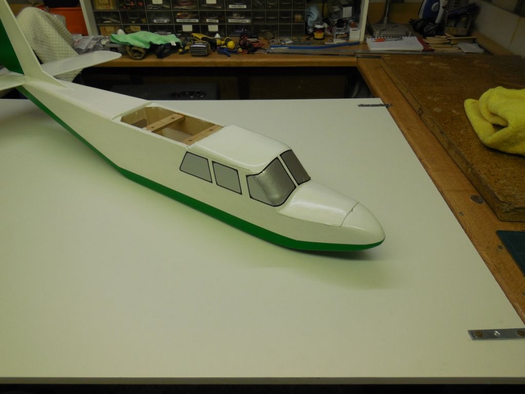
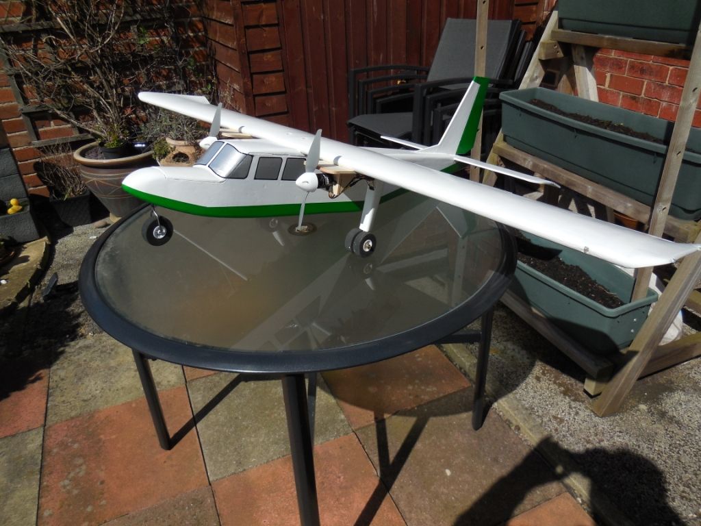
It's got to that part of the build where I am watching paint dry.

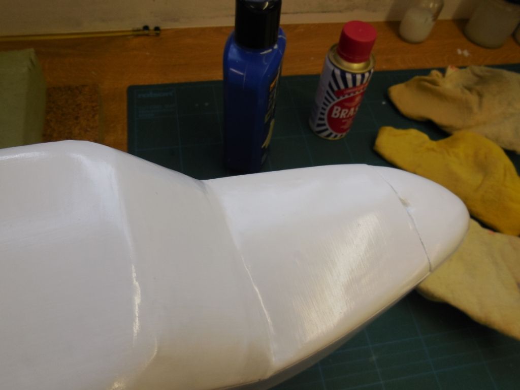
 The plane was painted twice with each coat sanded down using wet and dry (as before) then a fine polish with brasso and car polish to get a shine.
Masking of the air frame was done and paint applied
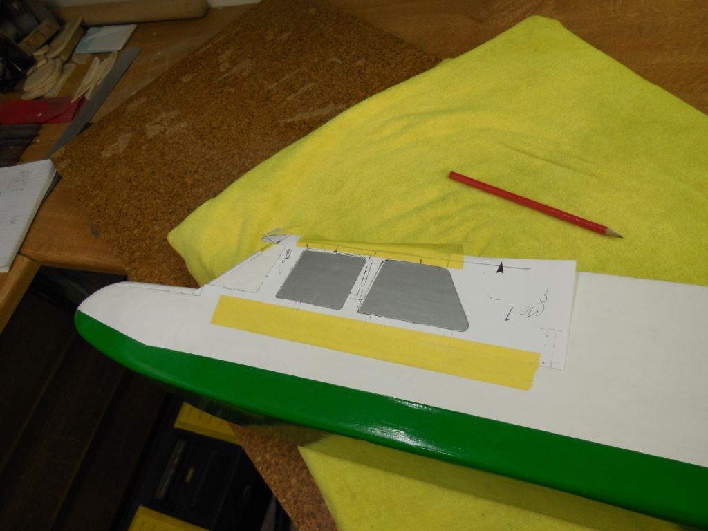
 The windows were marked out using a card stencil
Silver solar trim was cut and applied
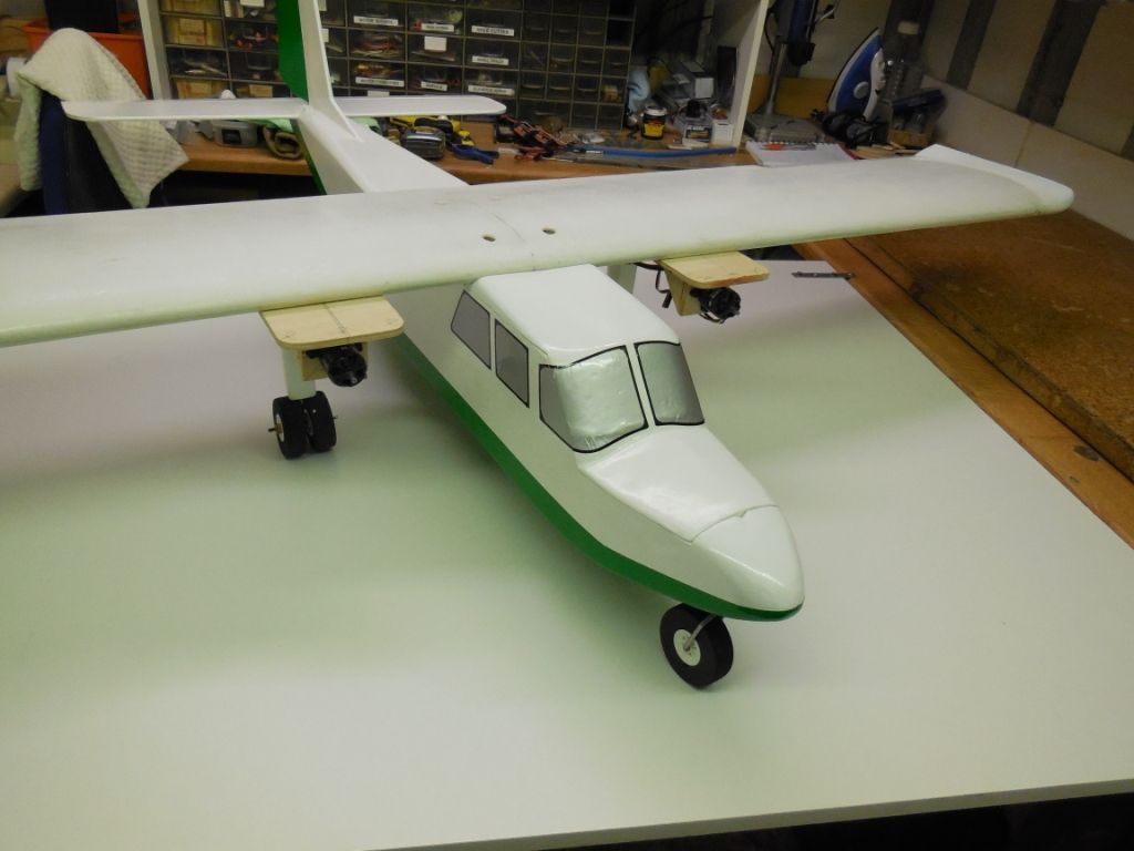
 The windows were highlighted with black trim and marker pen
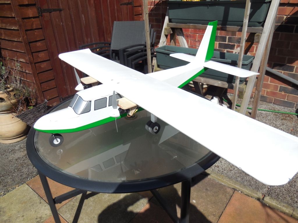
The main wing was attached
and out side pick's were taken
A small breeze blew and she took a take of position.
Is this a good omen

Till the next time
Thank you
Chris
-
I was not happy with the fitting of the hatch to the fuzz .
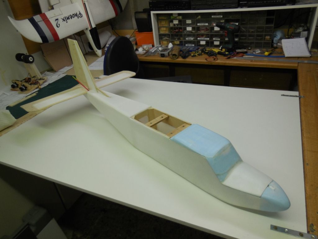
So 3mm depron was glued and sanded until a satisfactory fit was achieved.
The "nav" lights were then installed in there final position.
Time now for a cautionary tale.
I felt the need to look at the light show on the wing. So I connected an ESC & receiver and a lipo battery to produce a 4.8 volt supply for the nav lights.
I had powered the lights previous to skinning the main wing and they worked fine.
I don't have any photo's of what happened next as it was all a bit quick. The battery was connected and within milliseconds the battery was disconnected as it had reached a temperature that my hand could not stand as well as swelling in an alarming way. The battery was thrown out of the garage on to the concrete drive and left for over an hour to cool down. The ESC was so hot it had melted the plastic covering on the heat sink.
I could not understand what had gone wrong, the ESC had been in use in another plane, the Rx had been in use in the same plane with no problems. The light came on and the penny dropped. I had converted from JST to XT 60 connectors on all batteries and ESC's.
The fault has been found to be my incorrect connection of the ESC. I had soldered a positive wire to the negative terminal of the connector and neg to pos. This gave a direct short to the battery. In the words of Dell boy What a Pl****er.
I have now looked and double checked all of my converted connectors.
All I can say is check and double check.
This has cost me a battery and an ESC.
-
Hi Daz,
Great to see you back in the build zone. I watched your other builds with great delight and will be watching and following this build.
Don't forget this is a hobby/enjoyment and not a race to build.
You take your time and enjoy your build.
I will follow and enjoy your build.
Best regards
Chris
-
Martian, thank you for your concern about the extra work. To me it was extra pleasure because I enjoy building and I corrected my error. Thanks.

So down to work.
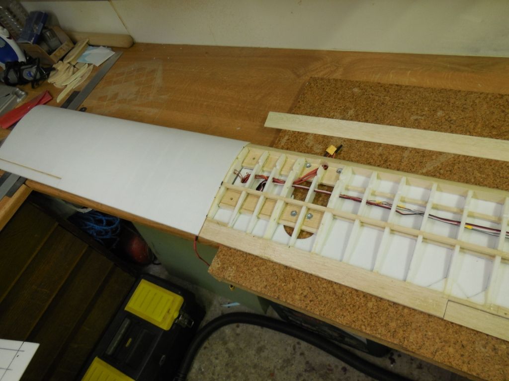
The wing wiring was tidied up as well as making sure all servo's and connections worked. As they all worked . The top wing was now skinned with 3mm depron.
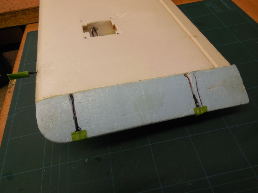
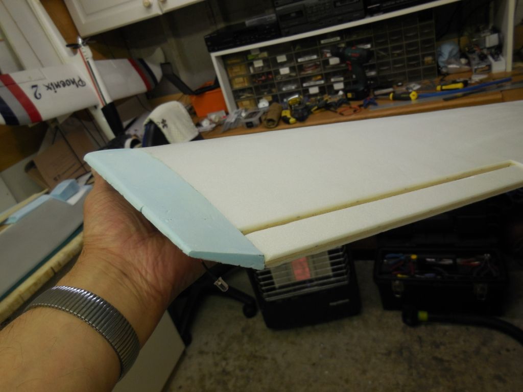
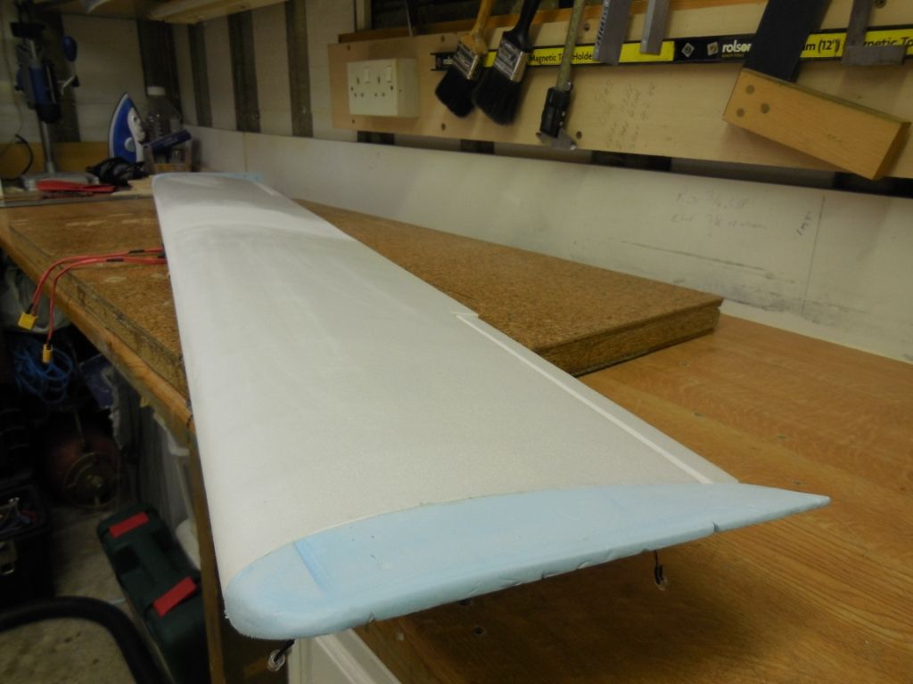
The full wing was skinned and the wing vortex tips were glued in place using P.U glue for a smoother join when sanded down.
The main wing was placed in position and the four wing bolts were drilled out.
The rudder and elevator snakes were fitted using 'Tie' wraps and glued with 5min epoxy glue.
The top rear deck was now able to be covered with 6mm depron.
The rear stabiliser's were aligned with the main wing and using P.U glue was glued in place.
Look at the gap between the rear wing and the main wing.

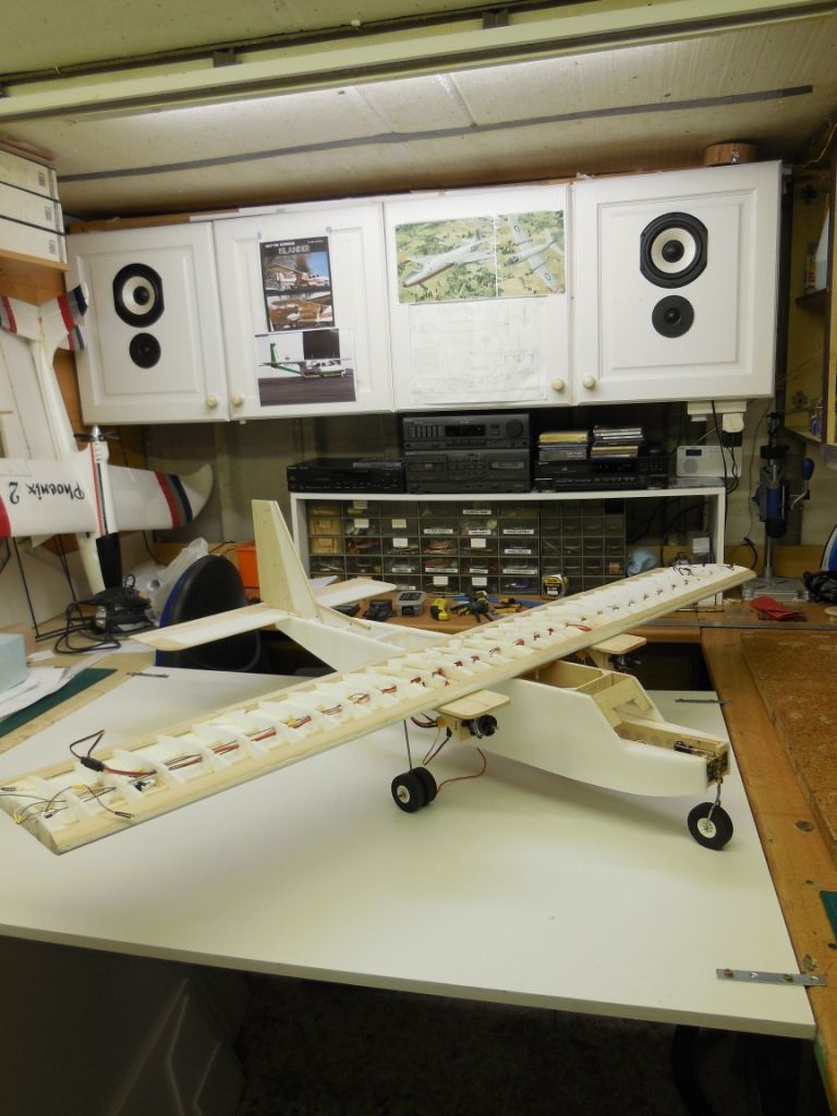
The result to date, to me , is a nice looking partially built Islander.
The next stage is the glassing of the plane. So it might be a little while till the next update, due to drying time.
Have a relaxing Easter break and I will be back with more updates.
Regards
Chris
-
Now, it's time to respond to Martian.
Firstly.
Thank you for saying you enjoy following my build, lets hope this continues.
Secondly.
You noticed my "Willy Wonkar" moment.
It has to be said you have passed the observation test and you now get 10 House points for being observant.

I totally agree with you that I had got the profile wrong.
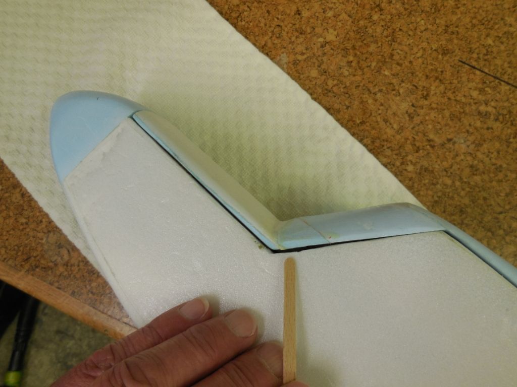
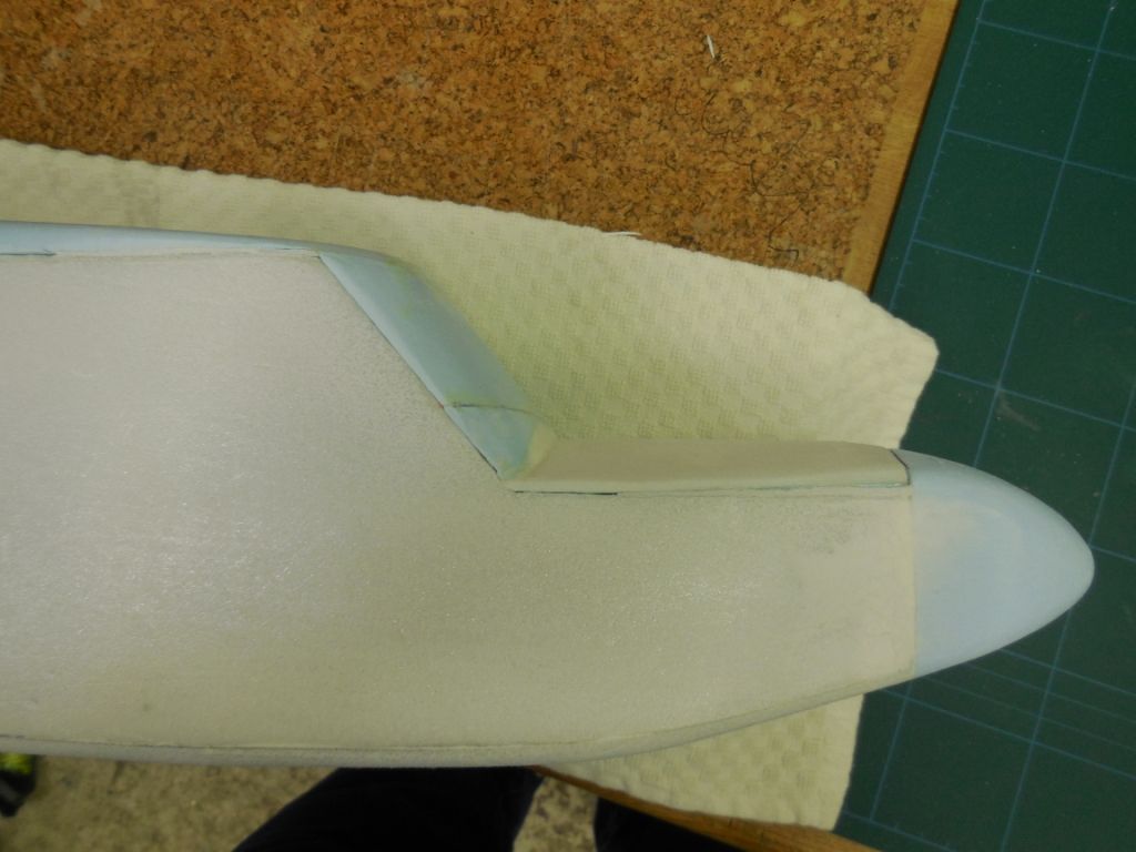
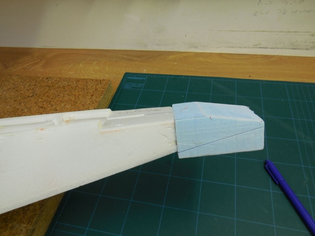
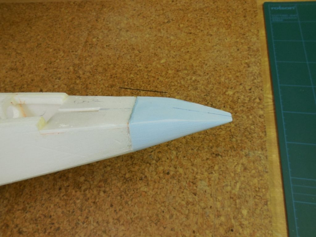
So a total rebuild of the fairings was required.
The old fairing was removed.
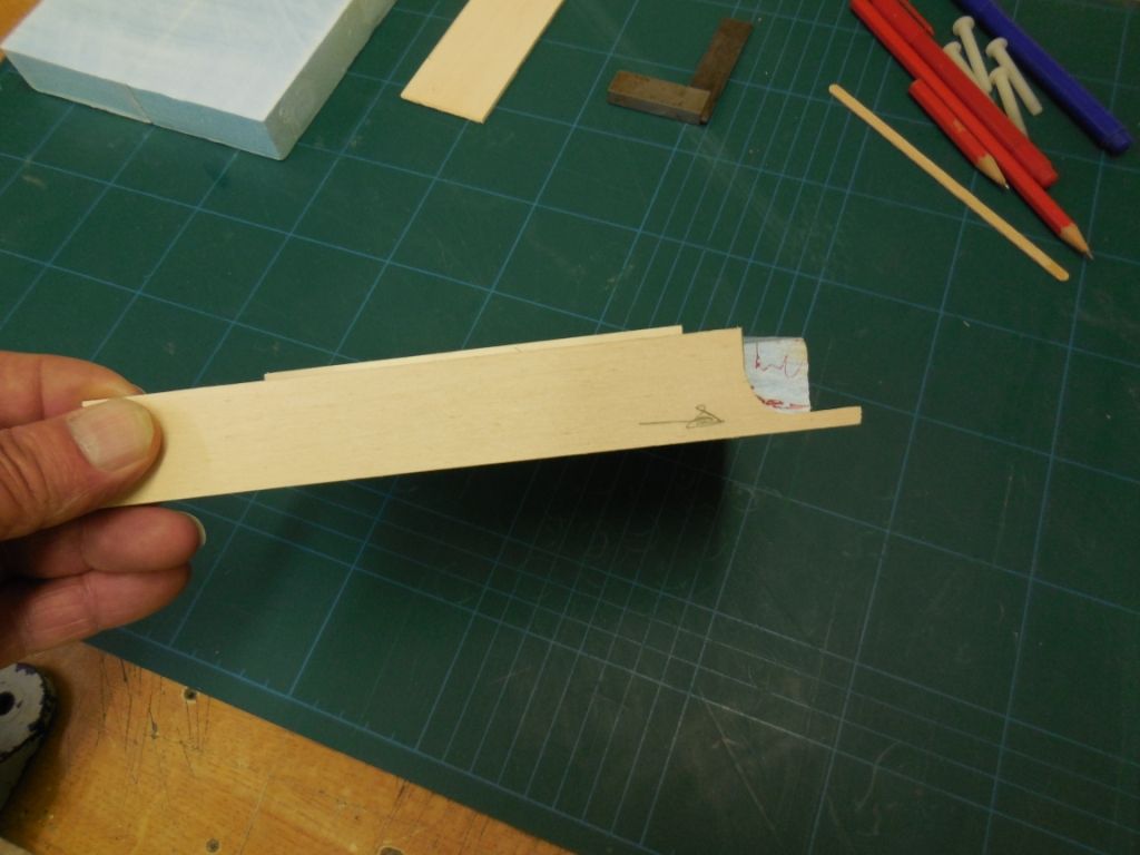
and using 1/2 inch thick balsa to make the new fairing sides.This made the front face 1 inch thick/wide.
Cutting and sanding got to this profile.
You can see the change in the profile from old to new.
Thank you Martian.
Keep the faith and keep following .
Chris
-
Wow!!
I'm amazed at the volume of people looking at my B/log, totally phased out with the numbers.
In reply to Keith.
"Orville" flies better than me (just ask Pilot Chuckles and Electriflier). I take off from a hand launch and arrive on a cricket pitch , if I'm lucky.

Colin, you say "can't see me going wrong with this one". Just you wait and see.

-
Thank you for the kind words of encouragement. Much appreciated.
Well a bit of good luck, the 'Wi-fi' was out last night. If the cat's away the mice will play So lets play!
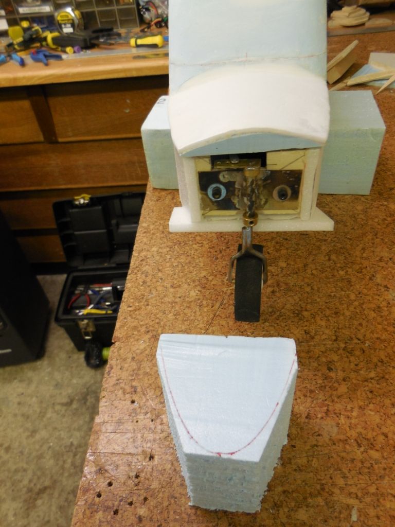
The main U/C legs needed strengthening, this was done using a brass strut(6.5mm X 1.5mm)
This was silver soldered to the main leg.
The U/C main legs were given shape by using 1/2" balsa L/E and 1/4" balsa sheet to form the profile.
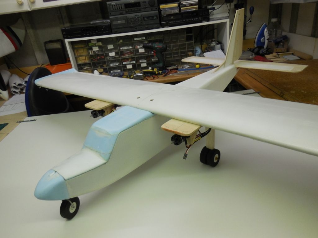
After a bit of sanding and cutting the rear blue foam 'pods' fitted to the contour of the balsa leg covering.
They now await filling and sanding when they are bolted down on the main wing.
Regards
Chris
-
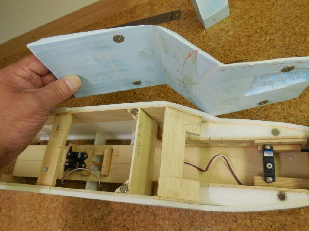
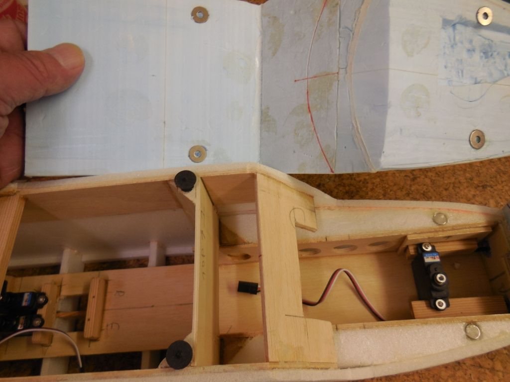
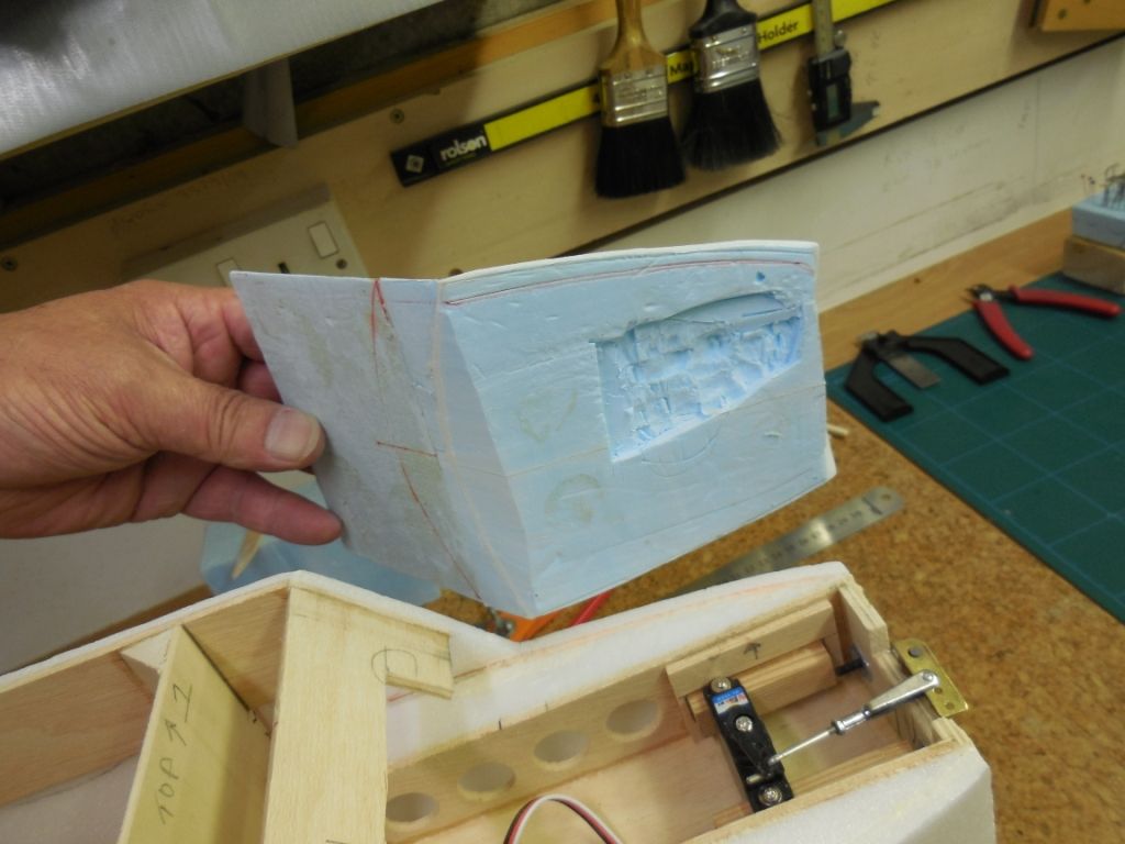
I forgot to say on my last B/log that the one piece hatch is held down with 4 rare earth magnets and by the main wing when bolted down.
I aligned the magnets by drilling a shallow 8mm hole and using a wood workers dowel locator to mark the other mating surface. The black metal 8mm plugs has a centred point to mark the opposite surface.
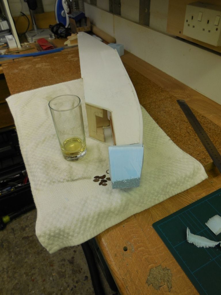
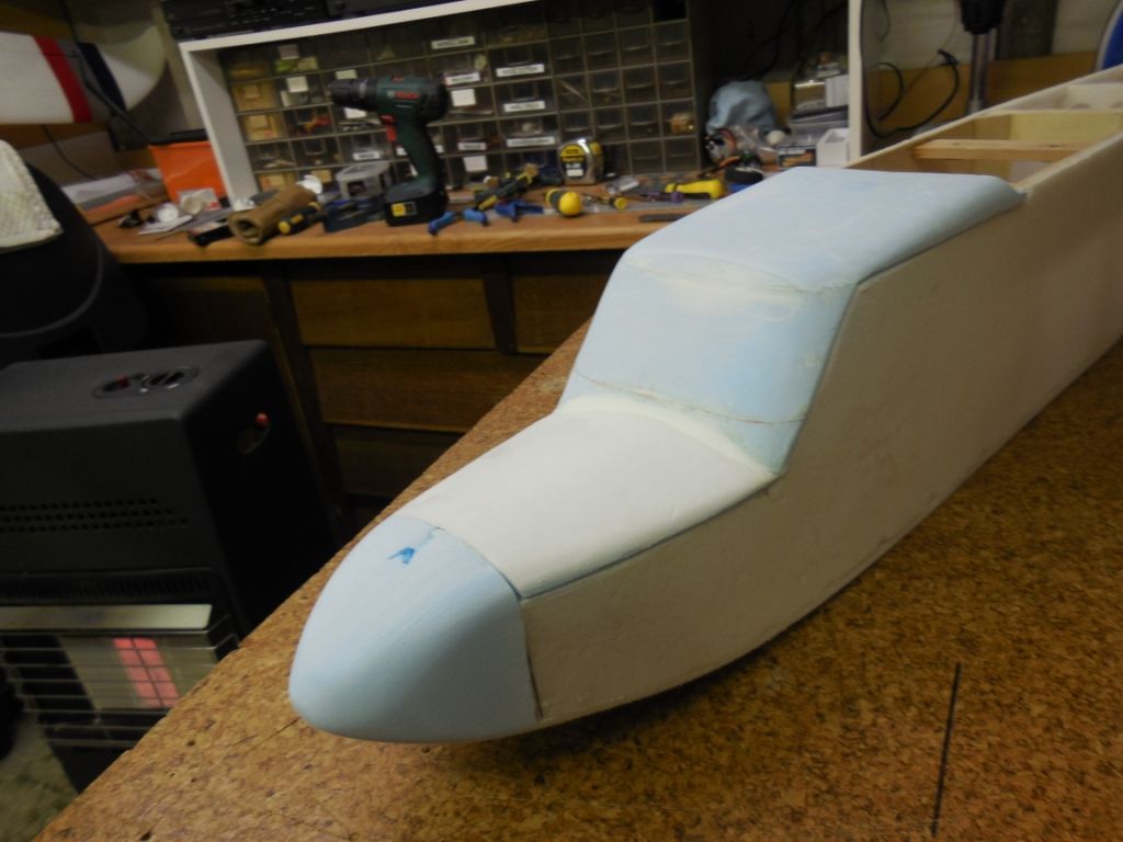
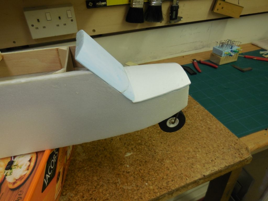
Next a blue foam block was pre shaped and glued(P.U) on the front ply former
When the glue was dry the "patient" was anesthetised and prepared for Rhinoplasty surgery (nose job)
Using a combination of a scalpel and a sanding block the nose was slowly formed and shaped
 The hatch and nose sanded to shape.
The tail section or "Rearplasty" was formed using blue foam glued in place with P.U and sanded to shape etc.
I've found that P.U. joints sand a lot smoother than Por glued joints.
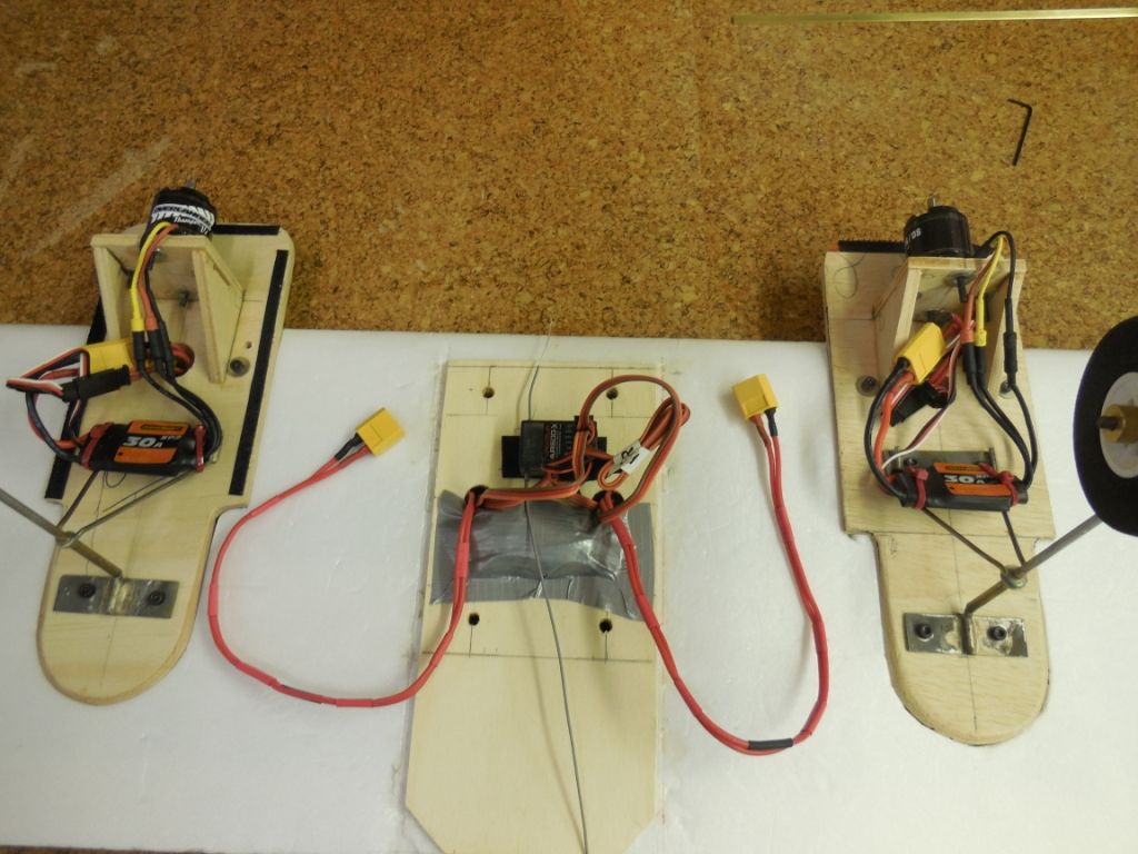
The wing wiring was tidied up ready for testing of the servo's and motor connectors before I skin the main top wing.
Under the grey tape is the landing light controller box.
Next on my list is strengthening of the main U/C legs and the skinning of the main wing.
As I always say thank you for following.
Regards
Chris
-
I've been a little busy recently organising with the wife ,my "ready made" daughters wedding ( Feb 29th ) Had 3 days of festivities and great enjoyment.
So it's time to do an up-date.
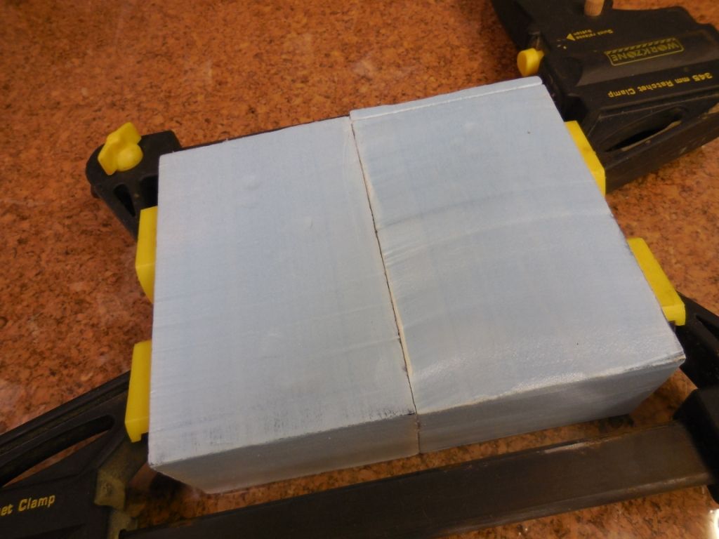
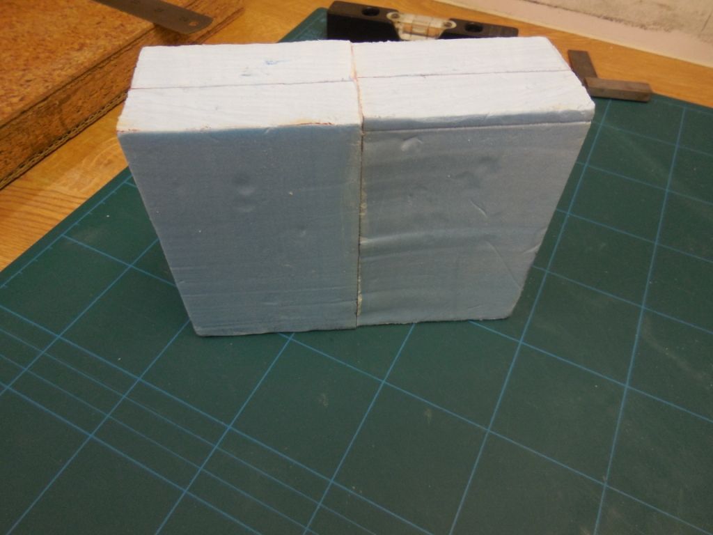
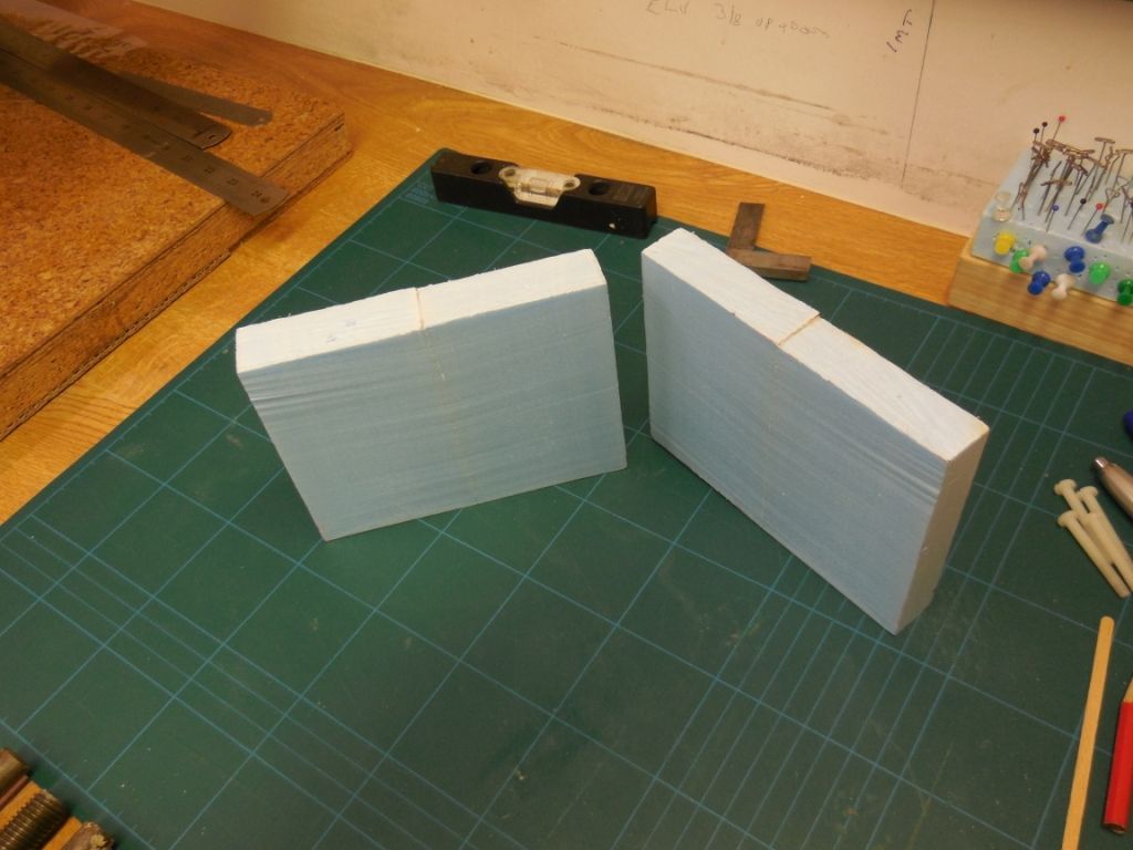
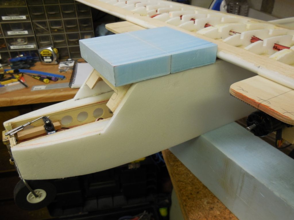
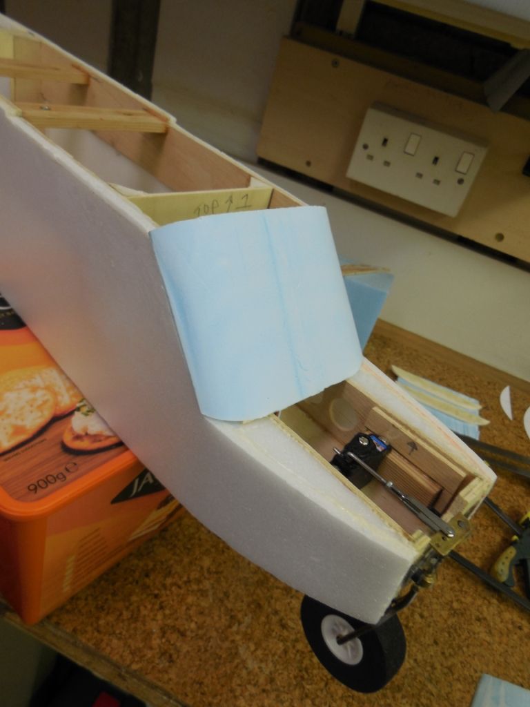
I was thinking about a hatch cover for access. I'd got some spare blue foam that was too small to cover the openings and not having the time to buy more. I had to think out of the box. I'm using a P.U. based blue foam and I'm using P.U. glue.
So why not glue the blocks together , let them fully dry and see if you could hot-wire cut them.
The answer is a resounding big yes.
This is the location of one section of the joined/cut blocks.
The foam had to be cut to fit under the leading edge. So templates were made to hot-wire the profile.
Cut to profile.
Other sections of glued blue foam were made.
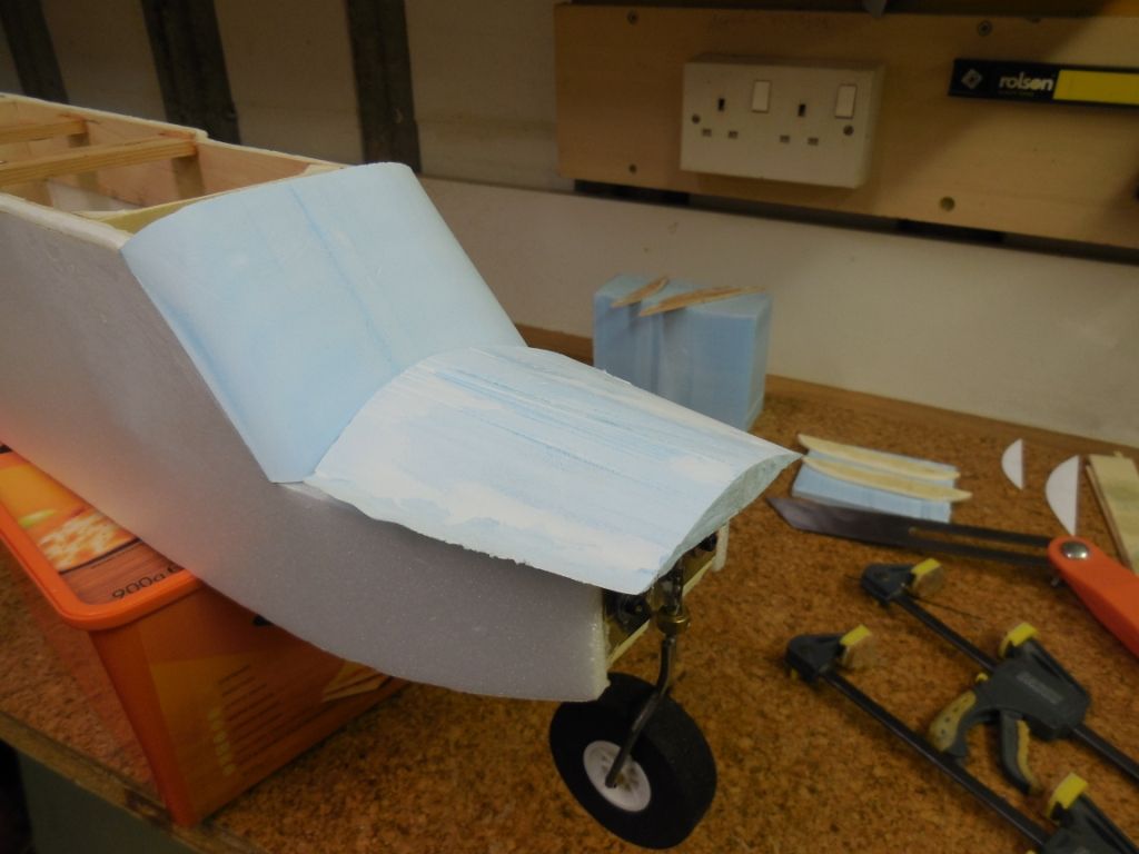
The lower nose section was cut first using templates.
The final finish was below par. Not the best result
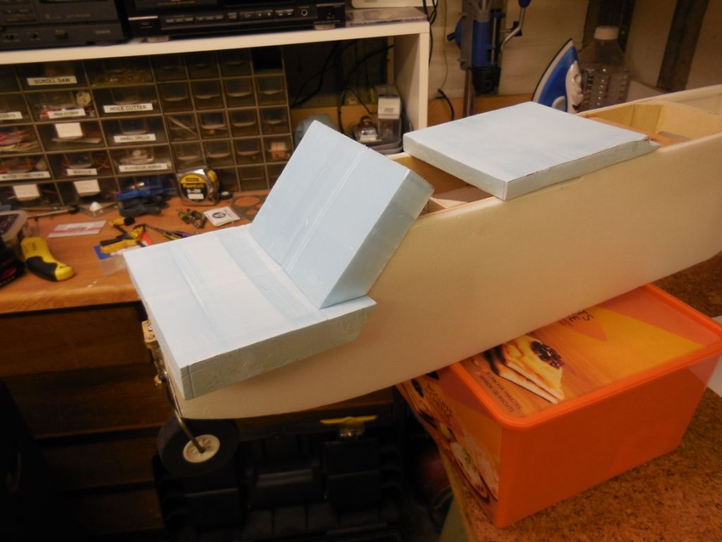
The next section was the sloping cabin front.
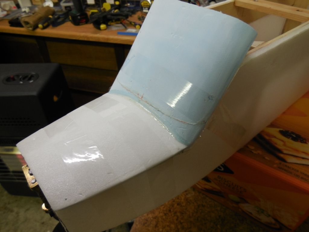
The lower front had to be cut to align with the cabin front.
These were glued and held in place with sticky tape until dry.
Glue dried and tape removed.
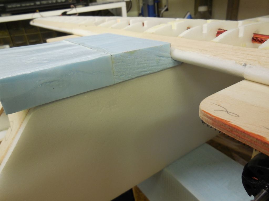
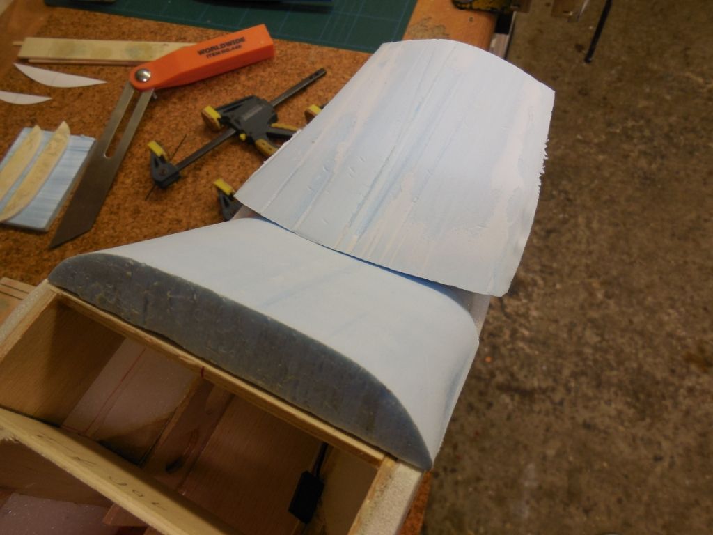
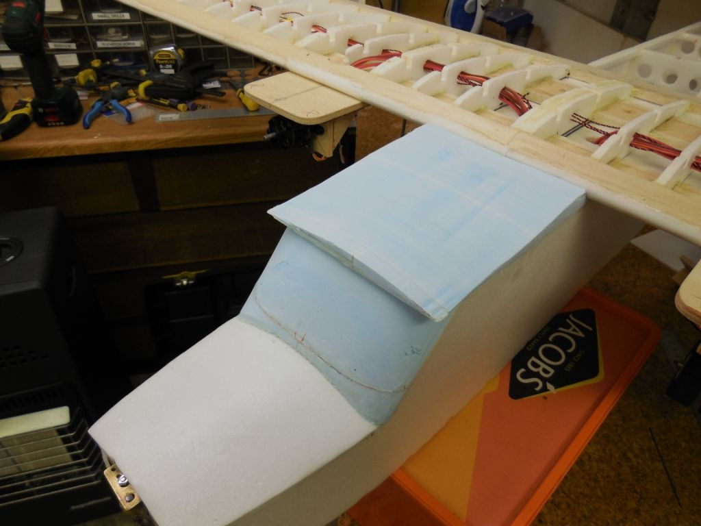
The top section was cut to give a radius curve at the front and a flat section at the L.E. of the wing.
The top section was cut and sanded to align with the fuzz and cabin front. Light filler was applied and allowed to dry
The wing was unbolted and the full nose access removed.
and sanded and refitted.
If thing's go to plan I might be doing a bit of cosmetic surgery next. Watch this space.
Thanks for following:
Till next time.
Chris
-
I sound like the local "copper"
"Evening All" I'm back
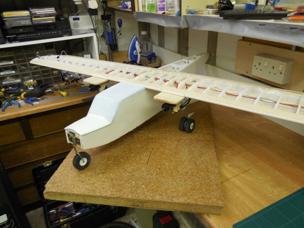
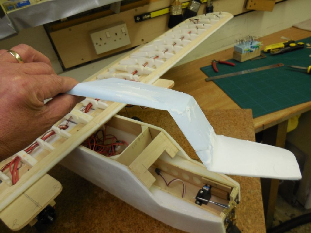
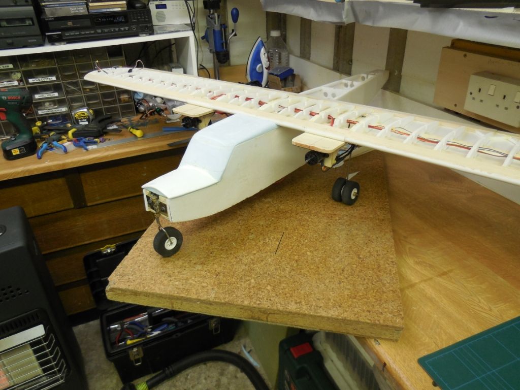
Now that I had made a rear stabiliser. It was time to align it to the "fuzz".
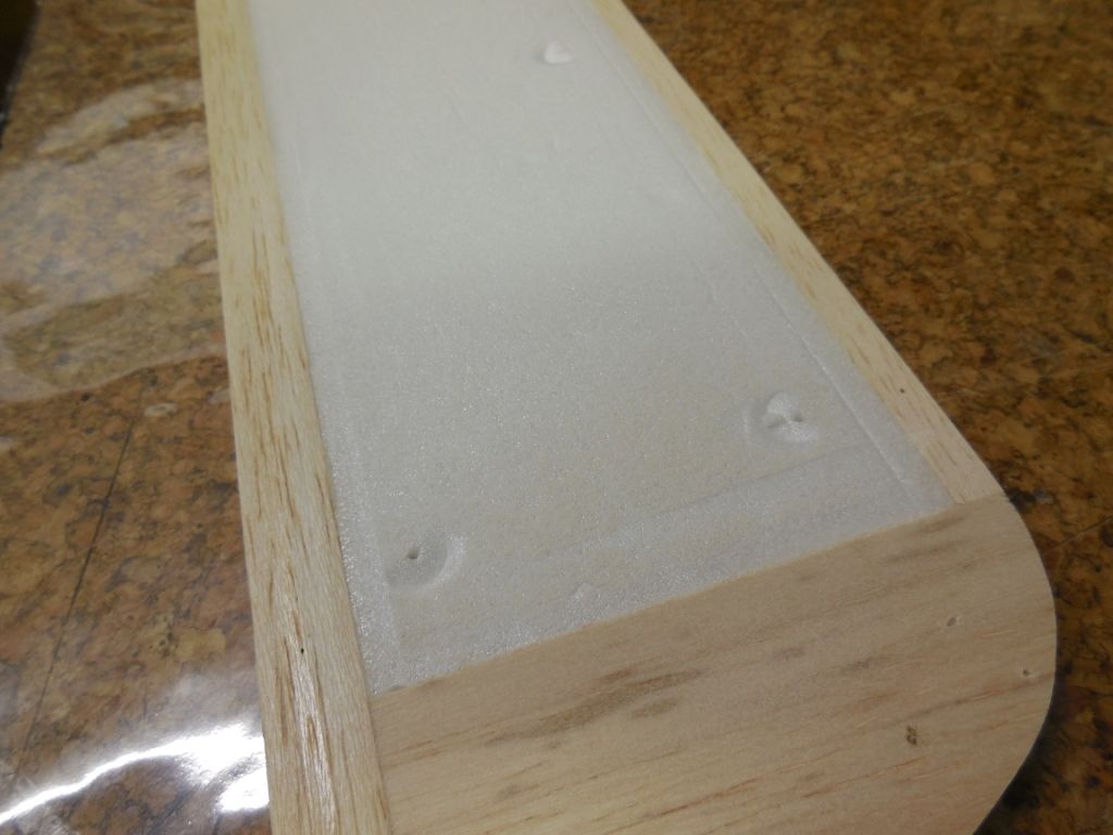
6mm depron doublers were glued /around all the insides of the "fuzz". These were then glued to the top/bottom of the depron skin So that I could put a small radius on the skin edges.
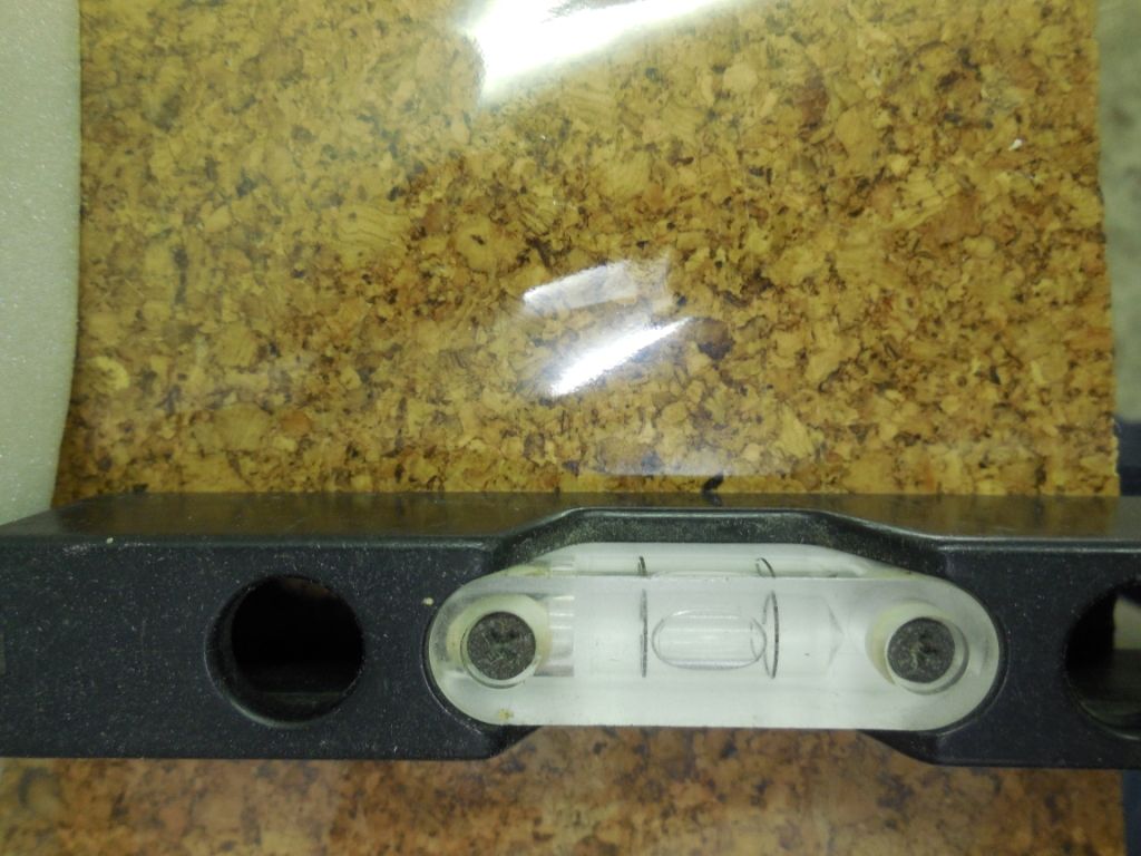
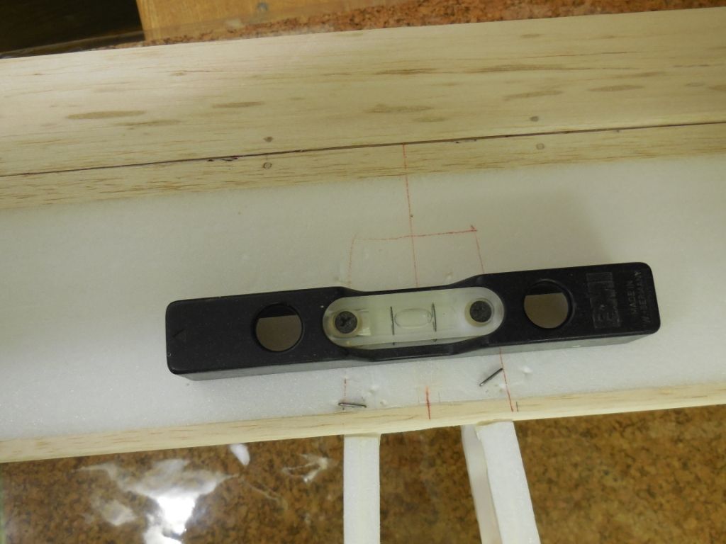
I knew the work bench was level
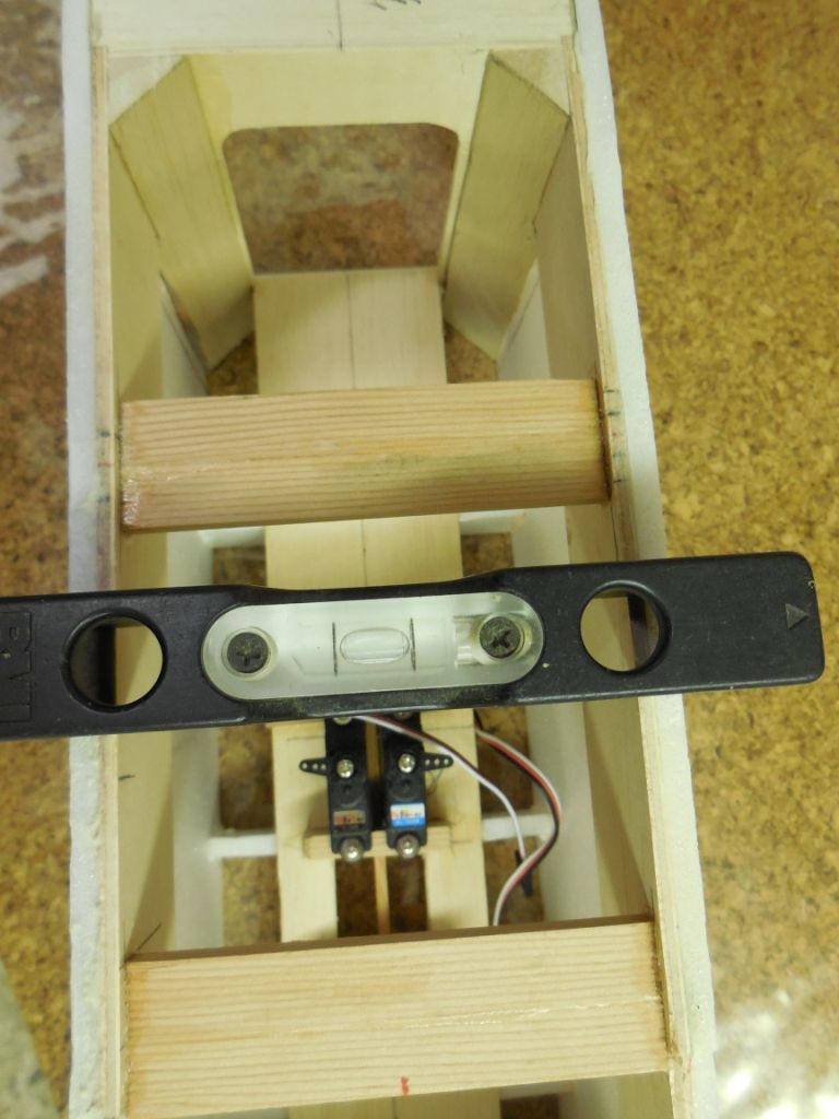
and I knew the basic "fuzz" was level.
The rear section proved level. The front wing location proved level
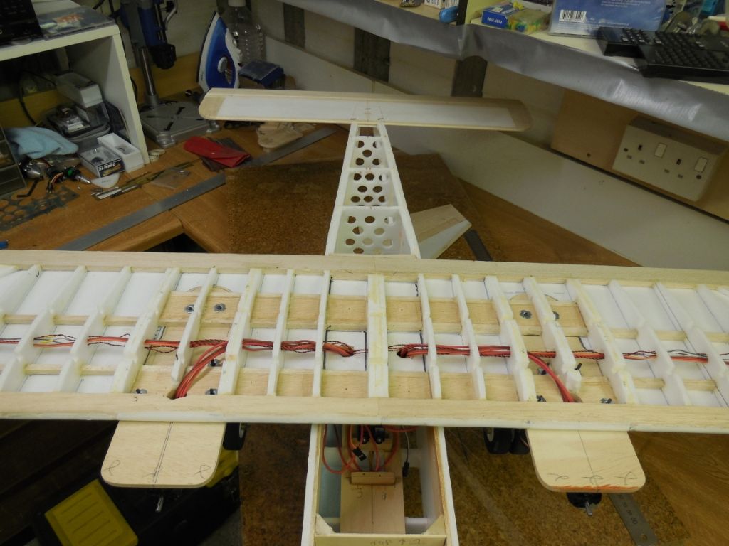
The rear wing was pinned down and the level checked.
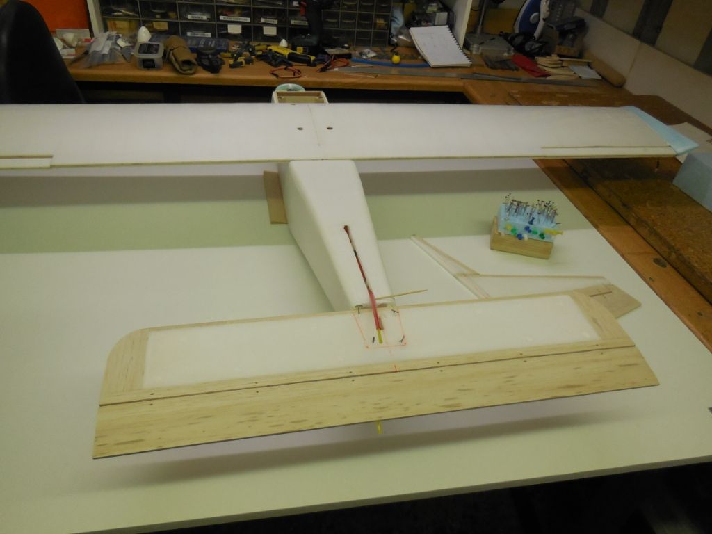
The main wing was aligned and if you look closely you will see 4 holes drilled to be enlarged for captive wing bolts to be fitted.
All measurements of the wings were checked and double checked for alignment. These were found to be as required and I think this as good as it gets.
As I've said before thank you for following. It's not a case of replies, it's a case of seeing people watching my B/log, that's what counts.
Thank you
Chris
-
Sorry gent's my computer died and I lost a lot of build pictures . What I'd like is a pointy stick and get Bill Gates in a dark alley to show him what I think of Win 10.
So I apologise for the quality of the pictures and continuity of pictures.
My next part of the build was the tail feathers. Without these fitted and aligned I cannot fit and align the main wing section.
So do I build a balsa wing as per plan or not.
Well I did say this was a composite depron /wood build.
So here we go.
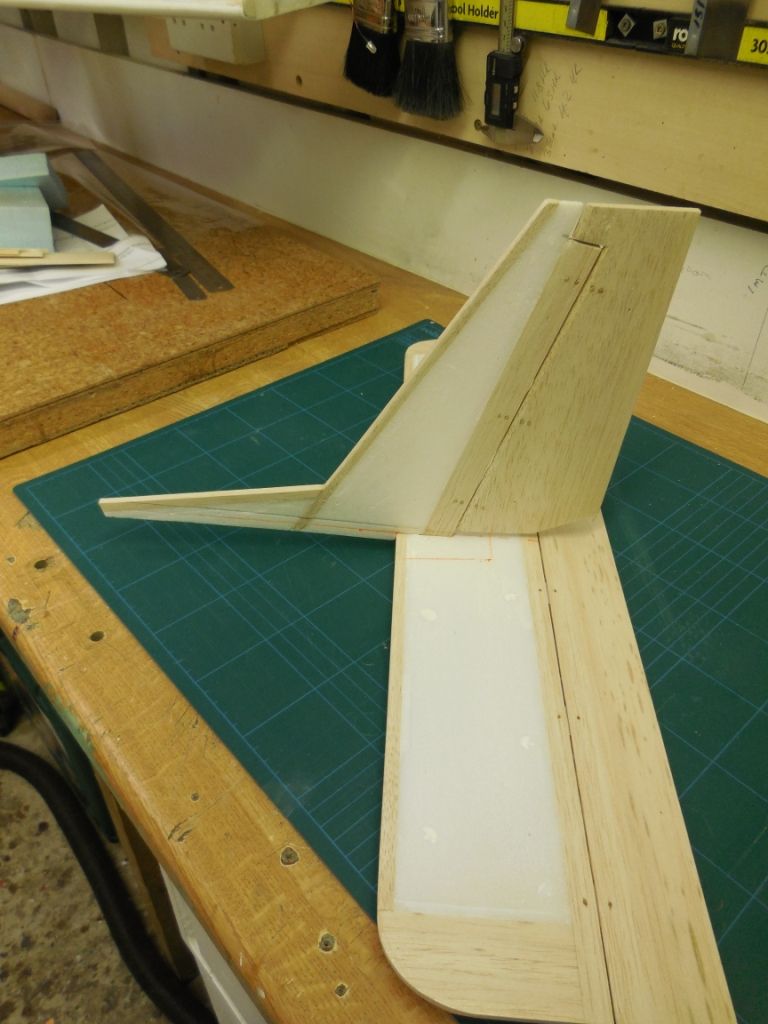
The upright stabiliser was built with 1/4" sq balsa leading edge and 6mm depron, using PU glue and clamps to hold and stabilise all the glue interfaces. 6mm and 1/4"" are a little different in thickness. So a plane was used to reduce the balsa, plus a little sanding and filler.
The rear wing was built first built using the same method but because of loss of info and picks I can't show the build.
The rear upright stabiliser and rudder was hinged.
I thought the rudder should be 6mm balsa for stability.
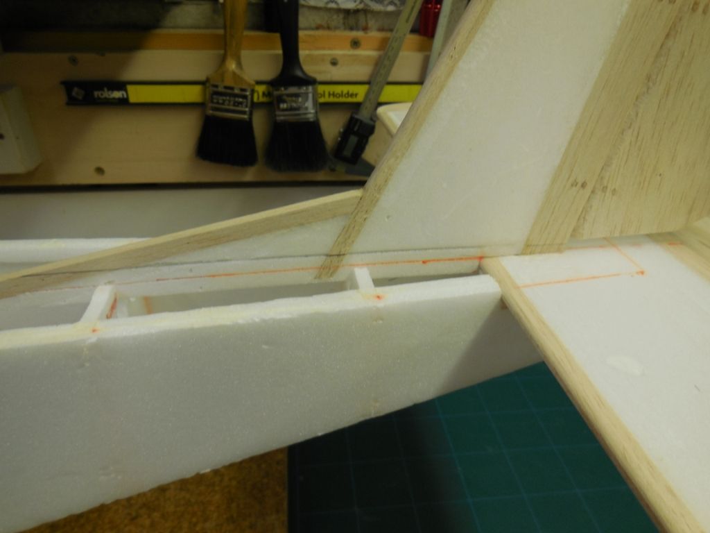
completed parts cut to fit.
parts fitted and marked to be in alignment with the fuz.
The black line is the top of the 6mm depron top skin.
I'll try to do a proper update very soon.
regards Chris
-
Hi Electriflier,
This a great build and fascinating to watch and follow.
Seems to me this Vulcan is having the same problems as XH558 did, problem of parts availability.
Now you have scavenged the servos from the 100" Vulcan, will she be grounded du to lack of certification.

I've had a look at my servo stock and found 4 new 17g (same as yours) which you can use if you need, just ask.
regards
Chris
-
Evening every one, It's that time again to try catch-up on the build, so here we go.
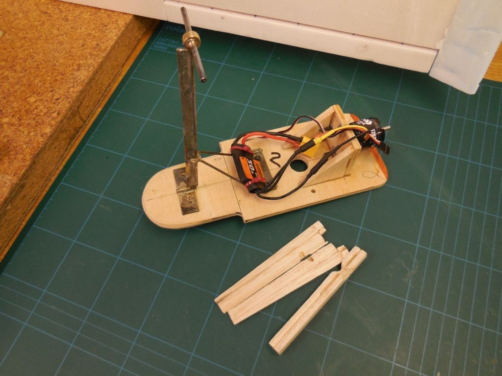
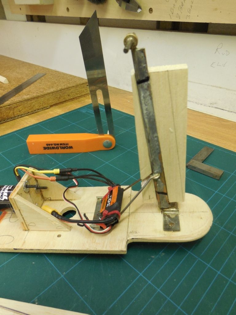
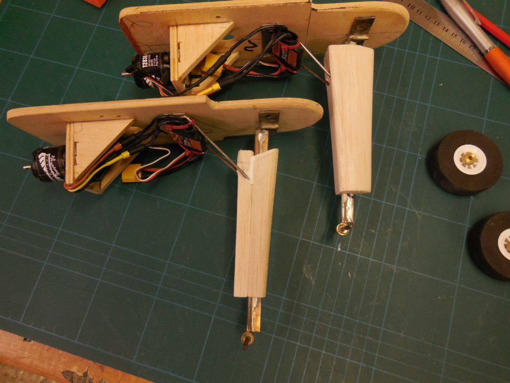
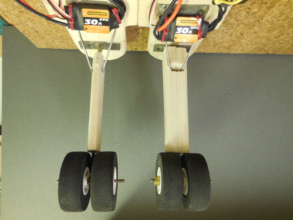
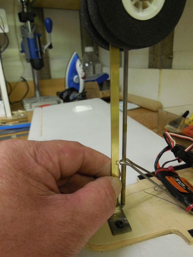
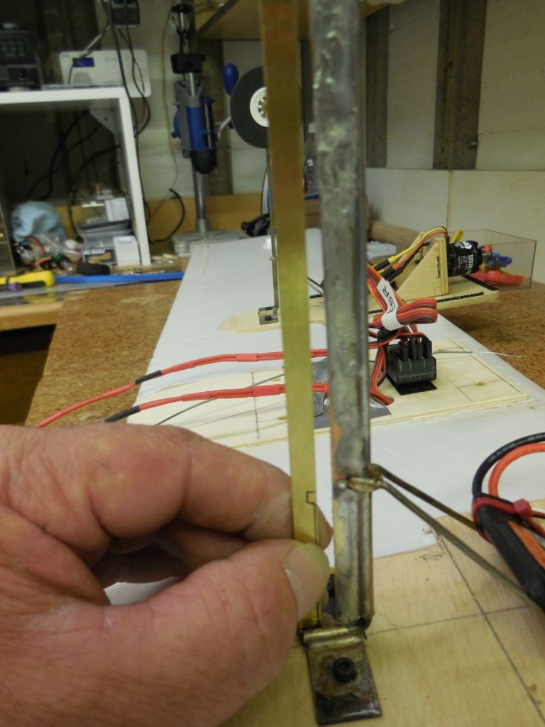
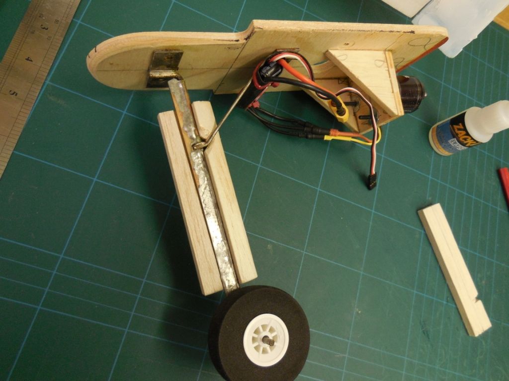
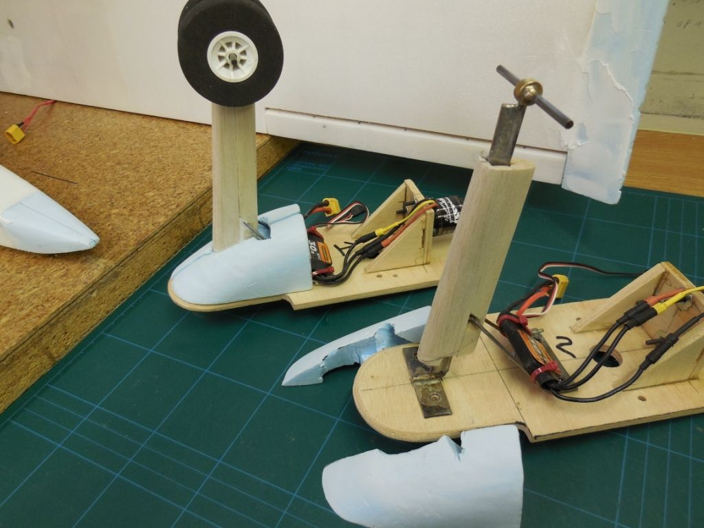
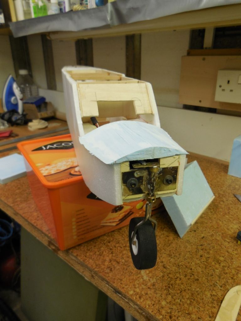
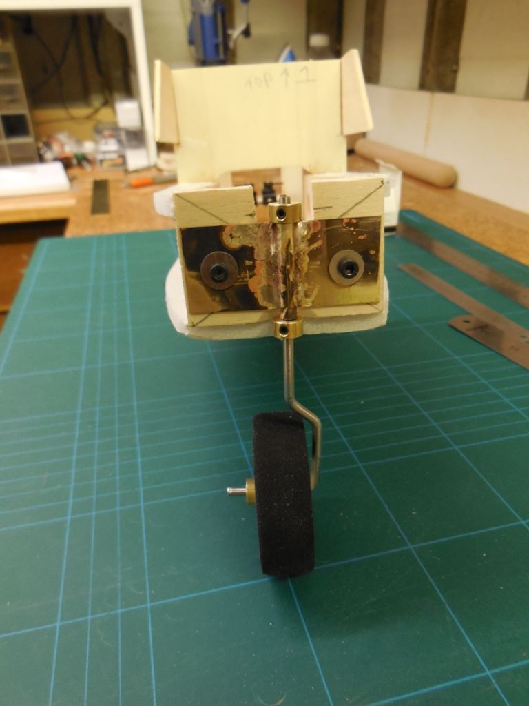
The nose leg required to be made semi scale
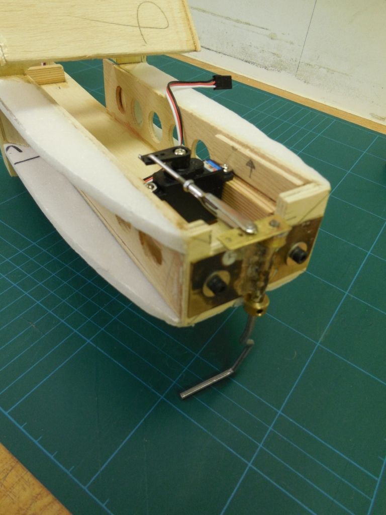
to convert from single leg to double leg the steering servo was fitted first
then the lower leg was duplicated and silver soldered in place.
Next the 6mm depron sides were cut
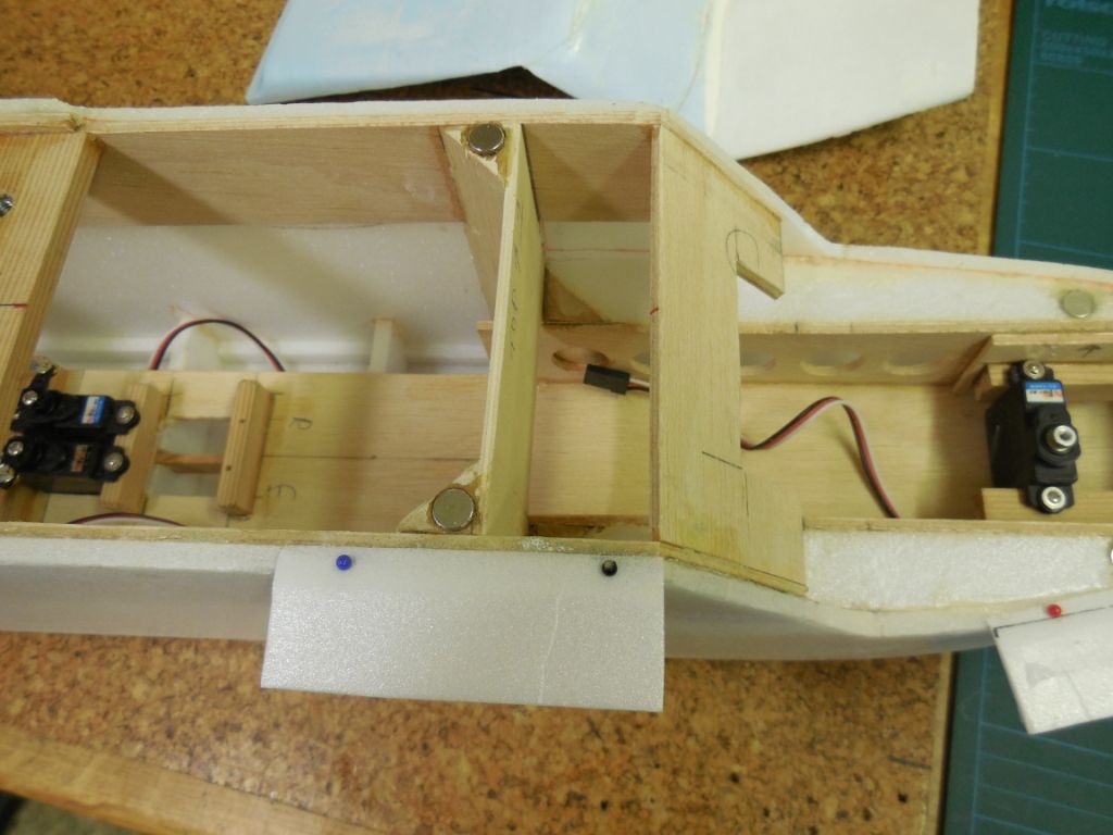
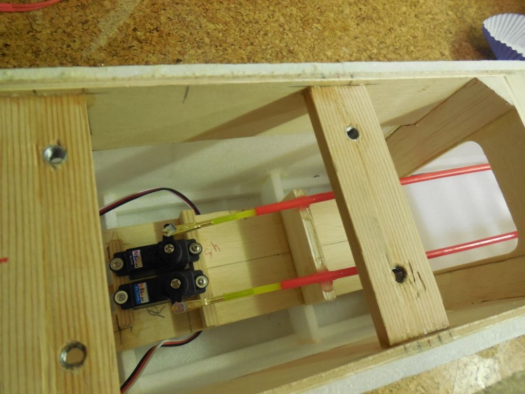
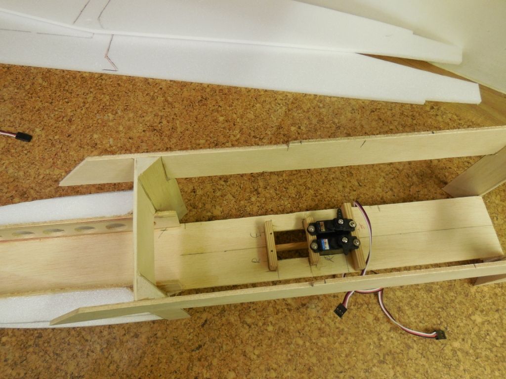
It was at this point that I realised that the location of the rudder/elevator servos were in conflict with the proposed front wing mounting plate. The servos needed to be relocated further back to allow access for my fat fingers. So this was done.
The ply plate base felt a little flexible after the changes so a 1/8"x 1/2" hard wood spar was added for strength. Yes I know it's adding weight, but for the right reason I believe.
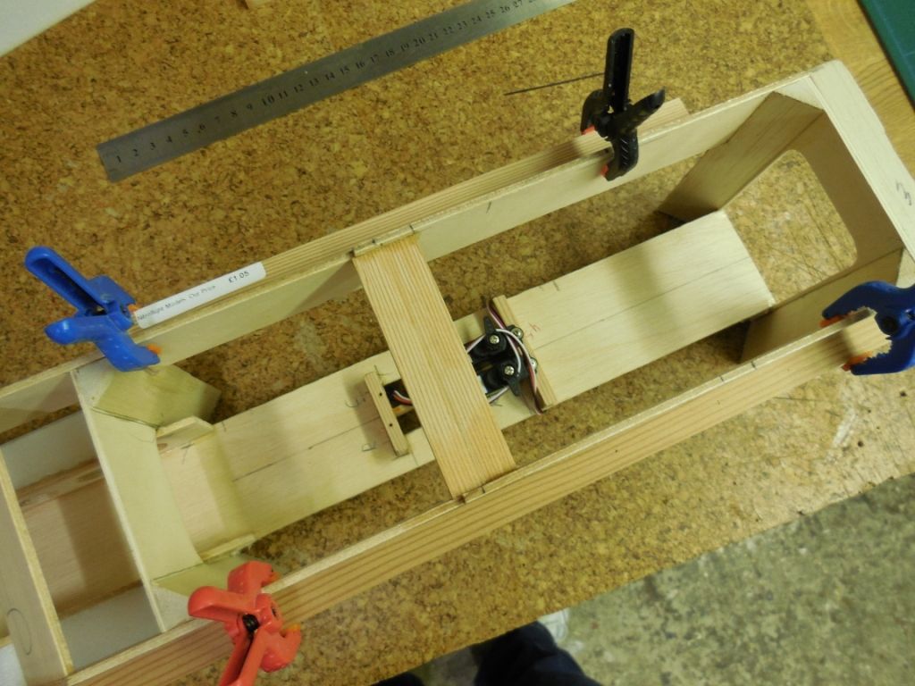
The first wing mounting plate was glued in place. You can see why I had to move the servos and bracing the ply sides to keep them straight while glue was drying.
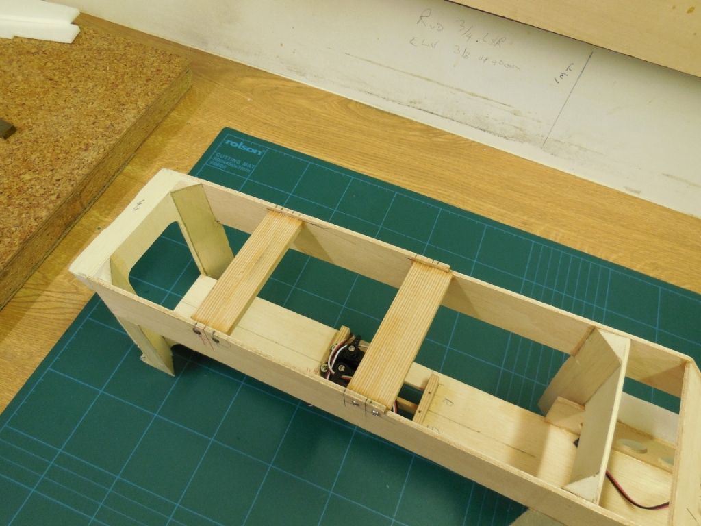
Both plates glued in place.
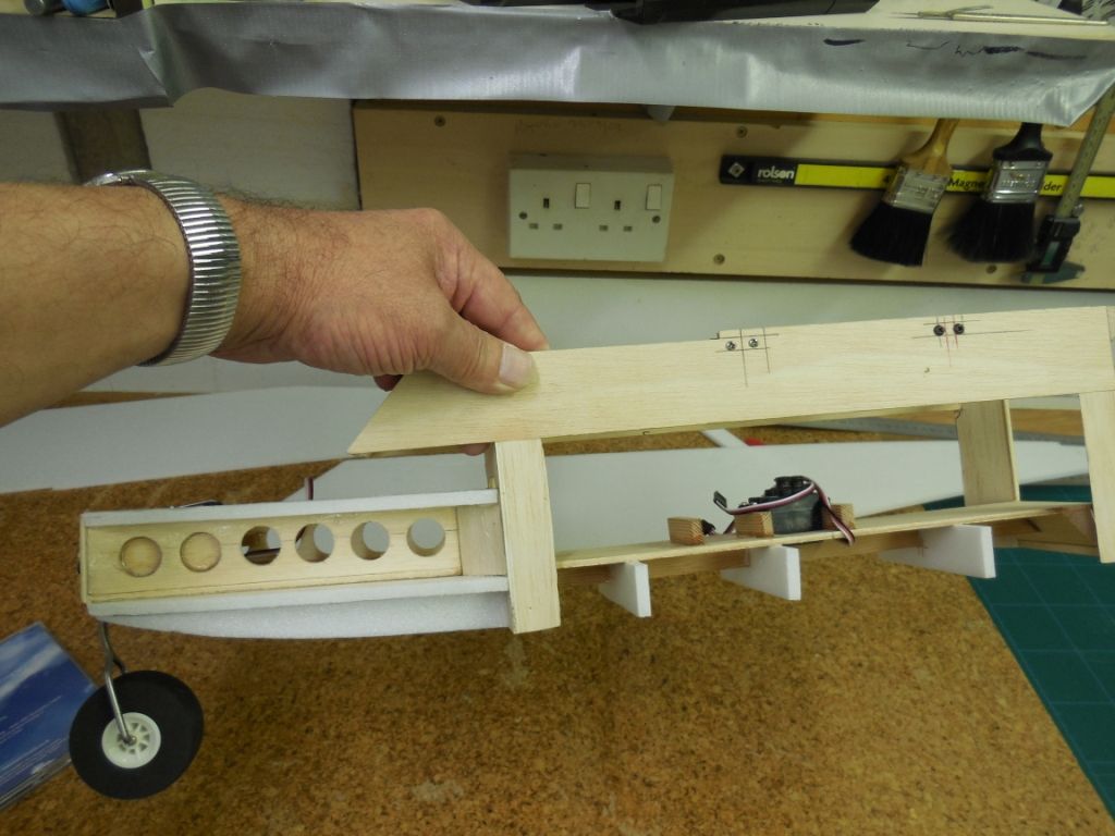
The wing plates were screwed through the outer 1/8" ply side for added strength because this is the main stress/load area of the fuzz.
Two front lower nose formers were glued in place as well as 6mm depron spars for the lower mid section of the fuzz sides.
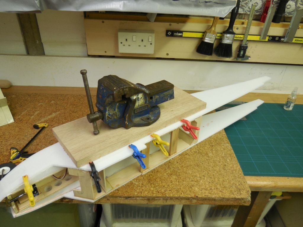
The 6mm depron sides were glued using P.U glue and a little help from a heavy weight to hold things in place.
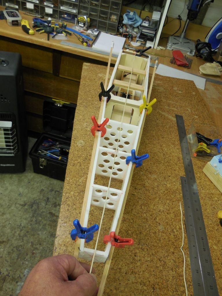
The rear sides were clamped in alignment using 1/4" sq hard wood.
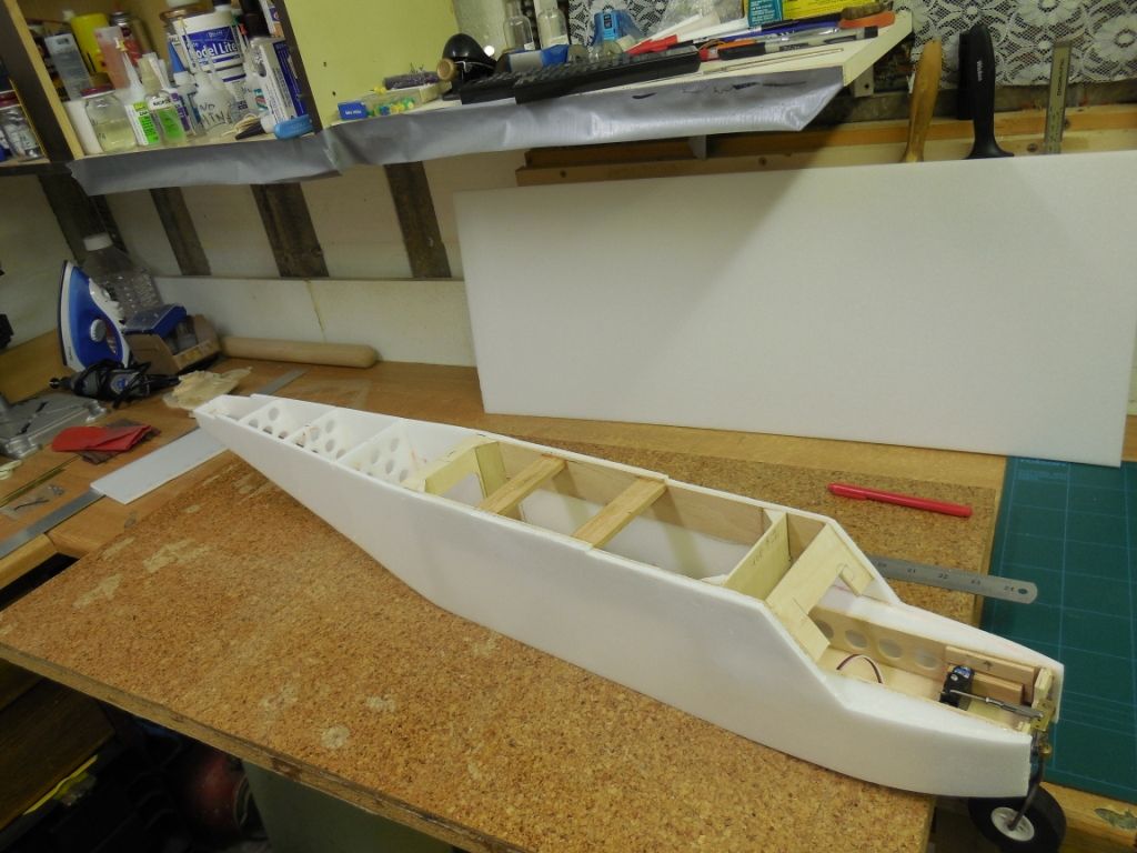
Three 6mm depron formers were cut/cored out and glued in place
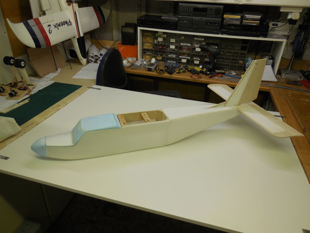
Alignment was confirmed using a taught string from the front c/l to the rear c/l
I'm happy so far with the build to date
I hope this update is acceptable, as all I seem to do is cut and glue depron. Nothing earth shattering or ground breaking. But then I am enjoying the build ,which is what It's all about.
Thanks' for looking and following.
Till next time.
Chris.





























LMA Elvington show 2019
in Shows, Club Events and Competitions
Posted
Hi Ken,
Been there to-day for the first time, the weather was almost perfect blue skies and the wind was almost straight down the runway.
The LMA pilots were fantastic and showed some absolutely amazing flying skills with their aircrafts. The limited trade presence was evident:-but they were positive about our sport/hobby's future and some bargains were to be had.
I bought a Blair RAF Se5a kit for £40 (should be £70).
There was good food to eat at reasonable prices .
The runway was split into two to allow the big boys / Jet jockeys to fly while at the other end was the "regular" flyers doing there thing
My highlight of the day was a young lady called Fiona.
All she wanted to do was build and fly a model aircraft, she got her chance of flying thanks' to "buddy" (she was 3yrs old) the rest is down to parents. The future is not lost.
If you get the chance go to-morrow.
Great day out
Chris and Bev