

Tim Flyer
-
Posts
1,890 -
Joined
-
Days Won
2
Content Type
Profiles
Forums
Blogs
Gallery
Calendar
Downloads
Posts posted by Tim Flyer
-
-
I ran in a new Laser 180 on my Chipmunk yesterday. All I did was set the carburettor idle needle and full speed needle with the cowl off (so I could adjust the idle). I also needed to set the minimum open setting on the throttle servo . The running in process is so easy. After a quick tune up that took less than 10 minutes to optimise settings the Chipmunk was in the air with the cowl back on. Nobody would have noticed I was “running in”. I flew my perfectly normal schedule and the engine didn’t miss a beat.
-
Thank you very much Lorenz for your helpful and kind comments .
I have recently just bought the duck egg blue and dark green and dark enamel paints so it will be a 1940-42 version as you said.
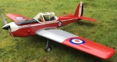
Now the cowl is finished I will start priming once the weather improves ? -
This last photo shows the bottom extractor scoop I put in place . Of course it detracts from scale but as you can see from side profile it is hardly noticeable especially when the wing is on .

-
 1
1
-
-
I have now got a bit further along. The air cooling for the cowl is done and dummy exhaust stacks attached. The cowl just needs a bit of tidying up with car body filler and then it’s ready for priming.
The fuselage is also ready for priming.
I’m also starting to assemble the Mick Reeves 1:5 scale instrument panel . This is very nicely detailed but a bit too big for the DB Spitfire but I’m modifying it slightly to fit by reducing the centre section and cutting in half. More on that later.
Another modification I made was adding a centre plastic wing bolt to hold the two wing sections together. This makes getting the wing in and out of the plane and setting up much easier without the risks of the wings coming apart an being damaged.

-
What would worry me using ethlylene glycol is it’s toxicity. If you are boiling it you may well be breathing the fumes which are poisonous.
-
I visited WW on Saturday. For me the purpose of the visit is shopping plus it’s good to meet some old friends.
Obviously it was extremely tough for retailers to visit this year but a number did manage it to their credit. SLEC and Component Shop and a few others were there albeit with reduced stock.
With the demise of high street model shops demand for retailers at events is surely likely to increase. When possible many of us like to actually visit the supplier. I have to admit that watching the flying at model events is not high up on my list.
This year I noticed a number of model boat clubs at WW and it was good to see them there and visit their stands. -
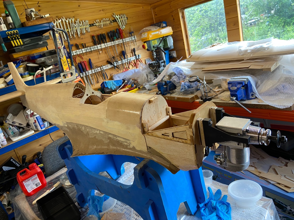
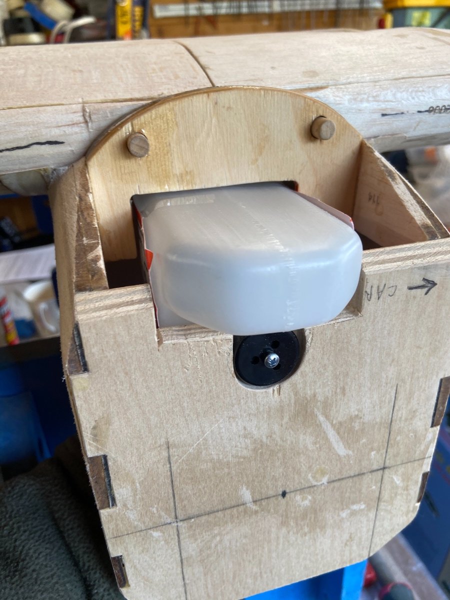
Thought I would do a small update after being a bit distracted recently.
The build is continuing although at a slightly slower pace as I slowly “bring everything together “.I continued the fit out the other day and mounted the air retract valve switch and servo next to the rudder and elevator servos on the front rails. The LIFE batteries and receiver will be mounted further forward on the platform above the fuel tank. After the fitting I removed the servos ready for fuel proofing internally. I always do that so a leaky tank won’t ruin the model. Once it’s fuel proofed I will install the pull pull rudder system but not connect it finally until after exterior painting. The long wire hinges in the kit should make the dreaded painting much easier!
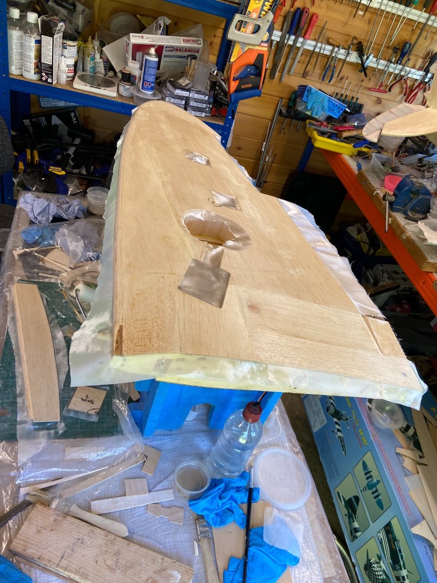
Today I glassed the bottom of one wing . Glassing is my favourite part of building now..it’s so relaxing. Since I bought the foam rollers from Bucks Composites its even easier and way faster. The foam roller allows minimum coating and no excess weight. It also seems so stick the matting down better and remove excess air far more efficiently than brushing.
-
2
-
-
I just bought my ticket the other day . I’m certainly looking forward to being able to get out and about there. I’m already preparing a shopping list , and hope to meet up with many of the usual friendly faces there ?
-
For myRX LiFe battery packs I use https://www.componentshop.co.uk/
They do some excellent LIFE batteries. I’m hoping they will be at Wings and Wheels at the end of June so I can but some for my new build . I typically use their 1600mah 2s packs . On most of my models I seem to get a power consumption of less than 100mah per flight .
-
1
-
-
Thank you Chris. I agree totally regarding engines, I’m afraid I have never yet seen a 2stroke in a Warbird that actually sounds nice. The moped noise spoils it for me . Regarding weight I’m also keeping the build as light as possible but I’m afraid I can’t give a realistic weight until I get a lot further on with the build.
-
By the way the cowl looks loose in the pictures as it isn’t screwed down... I put my usual 3mm threaded inserts int the cowl support blocks once screwed down the panel gap is quite small .
-
Cheers Ron. There is always plenty to be getting on with on this build. I can finally see the end . I will be pleased once I finally get the retract system in.
-
Hi all I thought it about time I updated this build log. I haven’t had much time to do modelling recently due to a number of family commitments but managed the odd few minutes in the workshop.
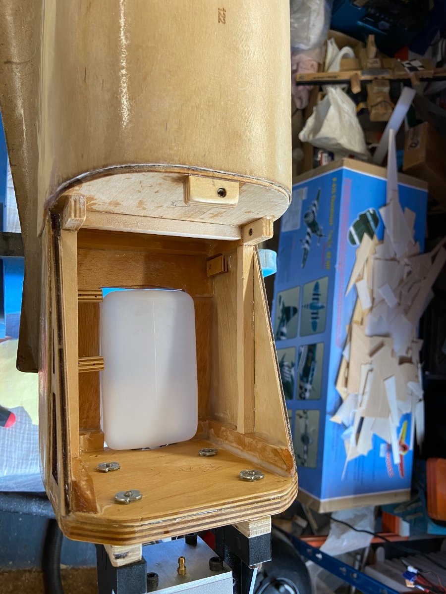
Regarding the fuel tank. I got the Dubro fitted but later on decided against it due to lack of room for an exhaust system. With the laser’s rear facing exhaust and close to engine tank there wasn’t enough room for the bendy pipe system I was going to use.
Jon was right in his earlier suggestion of a slightly wider but shorter Radio Active brand 16oz tank . That is what I have now fitted. It also enables me to use the standard laser exhaust. I added an extra sheet of ply to the back of the firewall to support it.
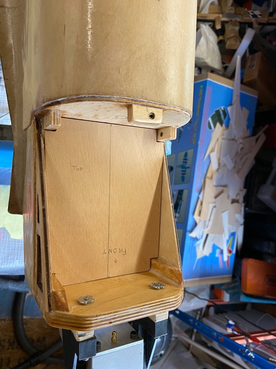
I have also added some wood reinforcement in the firewall area, and added supports and an upper floor in the tank bay which will be secured with servo screws to enable access to the tank and throttle servo below. This upper tank bay floor will support the receiver and Rx batteries will be fitted at the front, and probably the retract servo and operating valve switch along the side Positioning the retract operating system at the front should also
help to keep the weight forward.
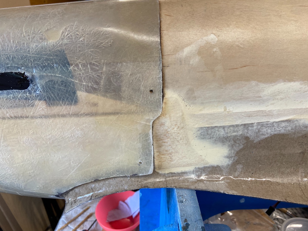
The fuselage is also glassed now with 25 gm /sqM cloth . I used a roller and cloth from Bucks Composites and the roller was excellent plus very fast and easy to use and enabled me to minimise resin use. I added small balsa cheeks with a bit of light filler next to the lower vertical cowl edges to obtain a decent rebate. I will simply taped the horizontal lower cowl edge later on to blend that into the fuselage.
I’m also sanding the wings and next job will be glassing them . I also have the pull pill rudder wire and cockpit to install before more hardware goes in .
-
3
-
-
Hi Chris I just came across this post . I’m really sorry to hear that it crashed . You did an amazing job building such an impressive model . I’m afraid I’m not expert enough to be able to cast any light on why it exhibited such bad characteristics in the air. Unfortunately it seems some full size planes make very problematic models.
-
I think it really depends on what we mean by air ram . If we have a large say 1.5 inch aperture directly facing the oncoming airstream, and feed that with a silicone seal directly into the carburettor stack I think that would have an adverse effect by leaning mixture at higher speeds. If by “ram air” we mean bringing in air to flow towards the carburettor with no seal so excess air can spread and pressure will not substantially change I think that would be positive. However the proof is all in the pudding as you both say. I certainly remember how important good airflow is on an RC boat engine despite water cooling. Performance massively deteriorates without good flow.
-
I’m enjoying watching the thread too . Regarding air intake to carbs it certainly should be in free flowing air and free from firewall restrictions. A velocity stack or bell mouth helps airflow considerably. I don’t think any sort of “air ram” would be beneficial. This is because the Lasers generally don’t use pressure fed fuel, and ramming with its extra air pressure might lean out the engine on full throttle.
-
By the way I bought the 16oz Dubro specially for this model as it fits perfectly with the engine . The extra “length” in the tank is actually taken in its protruding “lower nose” . I cut the bottom of the firewall to allow the nose through and a small disk for the filler cap . This means I could actually take the tank closer to the engine without worries of the filler /vent getting too close to the engine. The further forward tank also reduced wing cutting. It’s a perfect fit?
-
1
-
-
Hi Jon thanks for photos and great comments. The tank angle looks strange partly due to photo plus it was unsupported as I was holding phone to take the pictures . The tank is actually in line with thrust line when pushed in . I will eventually fix it in but plenty of other work first as I haven’t even fitted engine and throttle cable etc. Your thick ply idea is very good and I will be lining the whole cutout as you suggest.
-
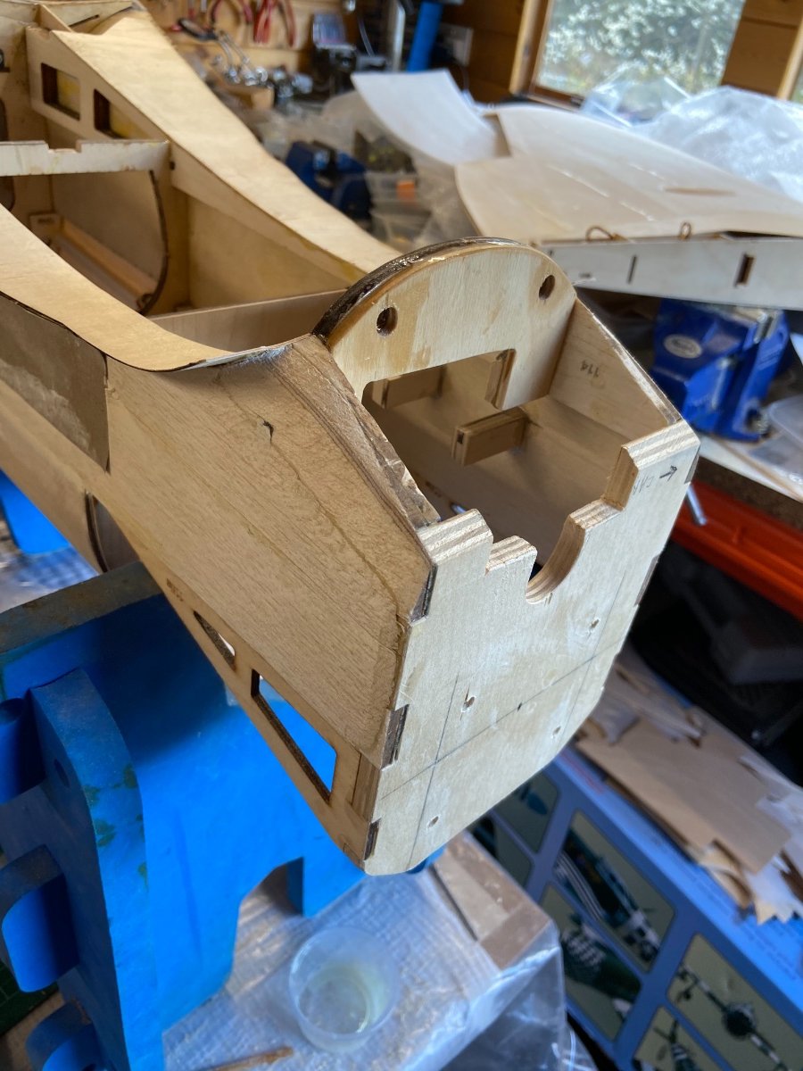
Progress has been a little slow while I’m distracted with household jobs but I have now drilled the engine mounting holes and cut the front wing brace to allow a lower fuel tank. I also added another layer of Birch ply to reinforce it the brace. I also added the throttle servo mounts . More front end reinforcement will go in a bit later.
The Engine will be offset from the firewall on its nylon mount with laminated ply beams.
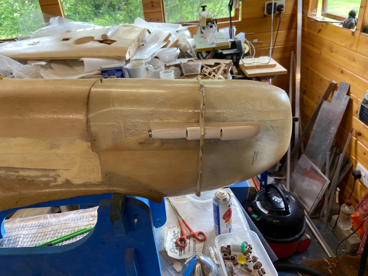
I have also cut the tank slots in the wings which will need tidying and filling with some extra wood. Luckily the wing slots just cleared the wing front spars as I also moved the tank a bit further forward and cut a slot for the tank cap in the firewall .
-
Wow thanks...some great looking schemes there . I don’t think I will put the cannons on as I’m in the “keep it simple camp” this being my first full Spitfire build. The Spitfire shape is such a classic and so many of those options look great ?
-
Thank you Jon that sounds perfect . The decals I bought were the standard DB ones “ZDB”
https://www.dbsportandscale.com/spitfire-mk-1a-kit-6502-p.asp
Hi Alan I do remember that scheme as I have it on an Airfix mk 1 assembled for my son some time ago. Having one wing black and the other white obviously is great for scale but I don’t think it would good for orientation in the sky as it might confuse and to be honest I’m happy just having if looking like the one on the box.
-
Hi chaps must admit I haven’t yet although for me the painting bit is my least favourite plus I’m a total painting novice for spray camouflage. I’m planning to use Guild Enamel enamel spray cans after the usual primer grey.
I just wanted to do the classic green and brown I think it is ? With duck egg blue underneath I think? I guess the cockpit and wheel should be primer grey or duck egg blue ? Advice on which Guild paint colours would be appreciated. I haven’t ever sprayed camouflage before! I have bought the DB decals, although expensive I didn’t fancy trying to do them myself.
Doing fictional scale is a good idea . I’m sure my final effort will be a long way from proper scale, but if it flies well I will be very happy ?
-
1
-
-
Hi Nigel. Thank you for your interest.
The fairings are formed of extremely thin ply.
I think the key to it working was gluing in the central fairing reinforcer correctly as per the template. This acts as a guide and centre line for the “crease”.
I then stitched the upper and lower fairings to that through the pre drilled holes in the ply. Believe me I’m no great sewing person but that didn’t matter as once it’s all in place nicely I ran the wood glue into all the edges and drill holes. Once dry I just sanded it lightly with 240 grit and all the threads disappear.
The Glue is only applied with a brush when the fairing was all in place . The very rear end of the ply required light dremmel sanding where it overlapped slightly. The rest had only very light filler as the thickish brown paper softened any line where it meets the fuselage.
I am now veering towards generally glassing all over just for ease in some of the tight areas plus the durability as the cowl scrapes the surface. I also already have a fair bit of glass and epoxy already in my workshop ?
-
1
-
-
Hi all . I’m doing a bit of tidying up and finishing on the fuselage before covering
I have also started to prepare the fuselage for fuel tank fitting and engine mounting. My chosen power plant, a Laser 180 with its low carb requires me to lower the tank to reach a satisfactory fuel tank/carb level . This will help to avoid ground level siphoning and over lean running when the plane is inverted .
I’m using a Dubro 16oz tank which is plenty large enough. It’s advantage is it is wide rather than tall so doesn’t raise the fuel level as much as the SLEC tank I had initially chosen. I will also need to cut a slot in the wing to give the rear of the tank clearance.
I have also been fitting the cowl. This required plenty of fuselage sanding and I’m pleased I hadn’t fitted the front wing fairings first.
The cowl is constructed of cheap super coarse glass sheeting as used in DIY canoeing and full sized watercraft and bonded with polyester resin. Polyester resin is quite brittle as is the course matting.
I’m quite surprised that quality kit manufacturers haven’t switched to finer matting and epoxy as bonding agent. That has been the quality way of glassing for a couple of decades now and is far stronger more flexible and actually lighter ( although cowl weight isn’t important here).
Having said all that the cowl does the job fine even if a little unwieldy.


Bates 1/5.5 Sea Fury Build
in Scale Matters
Posted
Well done Nick, was great meeting you at Buckminster and seeing your very impressive P47 . I will be following this build with interest too.