

.JPG.93118a2baf136c05371b08fbe1ca8ce3.JPG)
Andy J
-
Posts
1,370 -
Joined
-
Last visited
Content Type
Profiles
Forums
Blogs
Gallery
Calendar
Downloads
Posts posted by Andy J
-
-
Thanks JD, did see the construction method on the other link I posted yesterday so will now see if I can break the glue joint at the base of the fin.
Have you taken up some of the mods I have suggested as the 6BA cap screws makes assembly so much easier?
-
Found this old thread which seems to indicate that the fin just sits on a flat infill built between the fuselage stringers at the rear. So will see if I can slide a scalpel blade in to break the glue bond.
-
Think the wing is indeed twisted but don't think I can correct that.
Certainly the model was sitting lob sided as the undercarriage fixings was not tightened down. Nor does the rear section piano wire sit snugly into the recess on the underside of the lower wing so will have to adjust how the front legs interface with the leading edge to get it to bend down more.
Undercarriage is a solid construction currently JD. Will see how it performs once I have is fitting correctly. One mod I did do was to let in some M3 machined bushes into the lower wing since the rear fixing of the undercarriage saddle clamps have to be removed each time the model is rigged. Puppeteer is the same so will do a similar mod to that airframe. Bushes I used are obtainable from here. You do need to run an M3 tap through them as the M3 tapping is applied from both ends.
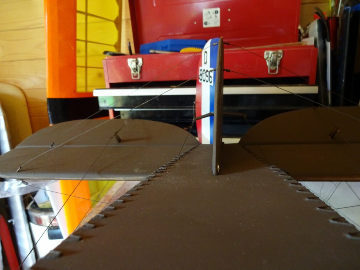
Unsure how I can also correct the lob sided fin as pictured as I don't know if it uses a simple flat edge contact to the fuselage or somehow it is let in to the structure or has a rear stern post which protrudes into the fuselage. Any chance anyone has a copy of the plan for that area? Could apply some torsion to the tail rigging wires to correct the lean to one side but suspect that will only cause the tail to warp.

-
Getting a lot closer now to getting the airframe in a condition it can be flown. Cap screws makes rigging a lot easier and will be replicating this approach on my Puppeteer.
Action man figure also added.
Some work needs to be done to the fin as it has the leans and also to the undercarriage which has a similar problem.
-
 2
2
-
-
Purchased these in the end so will report back if they are any good.
-
Certainly look what I was after but not a member of AliExpress so was unable to establish a price.
-
Have been looking over the last couple of months for some servo extension leads as my stock is running low. I Usually buy the JR 22awg twisted wire type with locking tabs but there seems to be a shortage of supply across the globe for the last 6 months. Yes you can buy singular leads, but I normally like to purchase multiple packs which HK used to sell as its far more cost effective. Has anyone else noticed this or perhaps found an alternative supplier of multiple leads.
-
Did a rough check on the CoG this morning and was pleased to find
 that the position was very close to the 130mm back from the leading edge. Did add a little lead though just to ensure it is nose heavy.
Whilst the cap screws do make the job of rigging easier the down side is that I laid in several ants nest that had popped up on the lawn.
New 13x6 prop from PropGuy does look good on the model.
Had to destroy the RAF roundels on the lower wing to get access to the servo leads which did not provide a reliable connection. Now looking for a cheap source but as the Type A come in at £18 approx for a 250mm diam version wonder if paint would be a cheaper option.
-
Well have done a bit more hacking and managed to get the old Y lead out and the new 22swg in up to each servo. Now uncertain if I solder up the new 22swg leads to make a new Y lead or take them directly to the Rx.
-
Problem was indeed the Y lead which had a Futaba style plug mating with a JR style connector. Also the Y lead is 18swg wire so would prefer to get it out and replace it with a new longer 22 swg wire which will get rid of one short extension wire which I also found in each wing. Unfortunately its proving impossible to pull the Y lead through so will have to resort to cutting some of the sheeting at the centre dihedral break to gain access to the Y lead connections.
-
At the moment both servos are being driven by a servo tester, so don't think its a signal issue. Will try a replacement Y lead but it will be a major issue to replace as the original is built into the wing.
-
Acquired a pair of SuperTec S03 servo in an old model, one of which is exhibiting a very strange behaviour. Both servos are fed on a long Y lead in a 91 inch wing. One servo operates normally but the other jerks around when commanded. Yet when I disconnect the good servo the bad servo operates normally. It almost seems that the good servo somehow affects the other.
Anyone have any suggestions as to what may be the issue?
Y lead appears to be quite a thick gauge of servo wire so don't think its a volt drop issue.
Yet to try a different Y lead to see if that is the issue.
-
PM sent re the O rings Jon.
-
Jon couple more queries also related to the Laser 75 exhaust.
What threading are the grub screws securing the exhaust and what size is the O ring.
Had to turn the exhaust to make it fit in the Flair Bristol and found one of the exhaust screws very tight so had to resort to brute force rather than an allen key and once I removed the exhaust I found the o ring could do with being replaced.
-
Used a file to clean the plate surface as recommended, whilst some of the 60/40 (leaded) solder took, it was not a 100% coverage. Also tried tinning an old steel 6BA nut which was also cleaned with a file but once again the solder failed to flow. So will have to look at using a plumbers flux as well as purchasing some new brass nuts.
-
On 12/07/2023 at 14:04, Paul james 8 said:II'm now looking to make the front struts but the leading edge of the top wing seems too low. Looking from the end the lower wing seems to have around the incidence I would expect (governed by all the meccano hanging off the bottom of the fuselage) but the top wing seems to have a fair bit less incidence, which would require the front struts to be a fair bit shorter than the plan.When I mention plans I don't have all of them, just the part that has been cut out and glued to the sample struts by the previous owner.Before I go any further is anyone out there able to advise on some reference dimensions from their plans or finished model?
Paul, would you like me to measure my struts given both my wings used the standard construction method?
-
12 hours ago, Engine Doctor said:
Re abrading steel for soldering dont use wet n dry paper or emery cloth as they leave carbon particles that hamper the solder from flowing. Use glass paper for cleaning / abrading.
Thanks ED for the tip of using the correct type of abrasive paper. Perhaps that is why I have had difficulty in soldering pushrods in the past. Sure I have some Copper Sulphate in the back of the cupboard but it may have got thrown out long ago.
-
What is the best technique to use to ensure the nut aligns up with the plate hole? Assume I simply tin the nut first and then clamp it to the plate with a spare screw and apply a little more solder.
-
Stuck with using BA as the model has most of the blind nuts fitted already. Its just the odd one or two that appear to have come off.
-
Need to solder some 6BA blind nuts onto what is I think are zinc plate fixtures. Could be steel plate but they certainly came from Flair originally and I suspect he used the same metal across all his kits.
The query I have is should I use brass of steel nuts to avoid any metal compatibility issues?
-
My wings are one piece so should only require 22 screws fitted as will leave the struts connected to the top wing. (well at least that's the plan.)
A small electric screw driver would be a good idea Paul. A Sonic type would be even better if I can persuade Doctor Who to give me his.
JD.... have you considered a correct CoG position yet?
-
Well the M4 clearance holes are now drilled, just now need 35mm M4's from MF which will be fitted from the underside.
-
Well its obviously the season for Bristol F2B's as I have just acquired one thanks to Ebay.
Interested in any mods that will make rigging easier. My airframe came fully rigged and it took a good 30mins to undue the 6bA strut joints apart using a flat bladed screw driver. First job therefore will be to replace all these fixings with 6BA cap bolts as sure that will make the job far easier. That will be also be a mod I will also do on my Puppeteer as that is a pain to rig.
When I get the laser 75 installed the next job will be to modify the throttle servo as the current position was far from suitable.
Tank is well back, but looks ok in height for the laser carb, so will keep its current position.
Given the undercarriage rear fixings have to be removed to allow the lower wing to come off, thinking the 2 plastic retaining clips secured by self tappers could be replaced with machine screws fitted into screwed standoffs let into the wing.
-
Well starting to be convinced that I need to drill the underside skin to allow access for 4 suitable screws fitted using an appropriate hex driver with self locking nuts on the engine side.
Will drill the bearers first using the engine as a template and then use a heated length of piano wire to burn through the contoured skin under before opening up to clear the cap bolt head.
.JPG.a859150c4acf49d3eeb4dd552e473e78.JPG)
.JPG.3c1865801a638e58e9d6196de76adb0b.JPG)
.JPG.9280789d2482fd7eb59f7280d27d1f41.JPG) that the position was very close to the 130mm back from the leading edge. Did add a little lead though just to ensure it is nose heavy.
that the position was very close to the 130mm back from the leading edge. Did add a little lead though just to ensure it is nose heavy.
.JPG.9fbe657c2da48962c43bbeccd14ea4de.JPG)
.JPG.e23ed08e7aa87097c92c6b4d82f17432.JPG)
Bristol F2B by Flair
in Scale and Semi-Scale kits
Posted
Well the fuselage weighs 5 1/2lbs but could not get an accurate value for the wings as they were too light for the scales. Would guess they are in the region of 1.5 to 2lbs.