


Bonzo Moon
-
Posts
308 -
Joined
-
Last visited
Content Type
Profiles
Forums
Blogs
Gallery
Calendar
Downloads
Posts posted by Bonzo Moon
-
-
13 minutes ago, Paul De Tourtoulon said:
Tell me about it, I also have a couple of 4s now 3s on my starter motors.
It's the way to go! I wonder how many people just bin them though?
-
I was testing an FPV tx the other day and like a fool forgot to disconnect the lipo until a while later. Put a meter on it and it read zero! Quite a recent 3s 800mA. I was not pleased. Checking cells I discovered that in fact it was only one cell that had gone to zero, two others were showing 3v + . I tried unsuccessfully to kick the zero cell into life by charging as NiCad, at NiMh, but it stubbornly stayed at zero. Reluctant to bin it I salvaged the 2 good cells and turned it into a 2s 800mA. Here's how
-
13 hours ago, Engine Doctor said:
Good luck wigh tesf flights Bonzo . EPP foam isnt harmed with most solvent based paint but do a check first odinary Polystyrene foam just melt with most solvents but takes artist water based acrylics well then a coat of Rpnseal waterbased clear to seal it.
As I said I thought mine was a Lidl glider , just plain white. Obviuosly not . Anyway it all a bit of fun.
Thanks, I'll give it a try sometime!
-
3 hours ago, Engine Doctor said:
Well done Bonzo Moon. I like your video👍 I bought a cheap SH foam glider from LMS for £6 as I was bored after Christmas and the field was cold and muddy . Thought it was a Lidl jobbie but looks a bit different to your model.
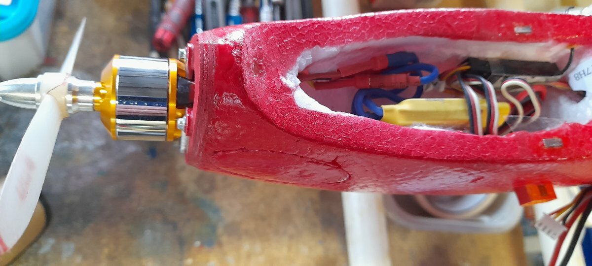
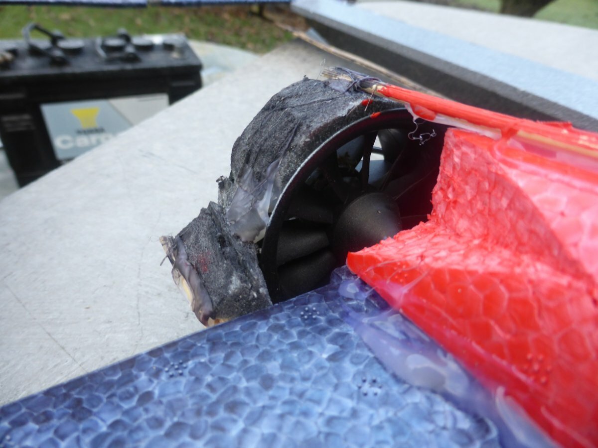
I stiffened the wings with carbon strip 1mm x 5mm and tail with 1mmx 3mm and fitted a 5mm carbon rod wing joiner. Elev servo was mounted under the centre of wing and some snake inner was use for the snake outer and 28g piano wire used for the snake , Horns cut from 1mm paxolin . The motor I used is way over the top at 2750 Kv but hey that's what the throttle is for . Battery is a 1250 3s fitted in a slot cut in the fuz opposite the wing servo . Test flight after a quick test glide and increasing Elev throw was excellent. Vertical performance is a bit OTT for a light foamy . All Painted now in bright red . I used cheap aerosols from local shop . Pics later .
Great fun per £ as most stuff came from the spares and scrap box total cost was £14 inc the £6 for the plane .
If anyone can identify the plane. It was just white foam with a two piece wings that plug in and a giant ball bearing in the nose .

PS Dont excuse the untidy workshop its always like that ☺️
That looks great mate! And I bet it goes well with that big motor. I've built 10 of the big Lidl's now and on my 1st I fitted an A2212 6T 1600kv , plus lots of carbon. It ended up quite heavy, but was fast. Nowadays I keep them light and use BR1806. Tiny little motor but it's more than enough. I've never tried painting a foamie. Worry that it'll melt the foam, mind you the Lidl are coloured foam so don't really need paint. They are great fun for experimenting with.
I've got about 3 planes needing test flights at the moment, but weather has been bad for weeks. Very frustrating!
-
My RC conversion of £13 foamie FMS Alpha jet gets its 2nd test flight after a very strange day at my local strip. Suggestions after the first pretty unstable maiden were tail heavy, but my research said it was nose heavy, hence moved electrics back a bit, added 2g of lead in the tail, plus a little more downthrust. This flight was much better than the first test, though maybe still needs a bit more downthrust? Messing about with cheap foamies can be frustrating at times, but it's a lot of fun and good learning experience!
-
Part 2 of my Lidl Big Bird build blog and a few of my tips for anyone thinking of making a Lidl foamie chuck glider RC conversion. I was hoping to maiden it, but I think it may be jinxed, cos it didn't work out that way as you'll see in the video! 😟
-
1 hour ago, Rich Griff said:
Nice one bonzo, keep them coming...much appreciated.
Thanks.
-
2 hours ago, Fly Boy 3 said:
Must admire your dedication and tenacity to get these little models flying well.
It is a measure of your modelling and flying skills that I admire.You have taught us a lot. Thank you
Thanks mate. They are a bit of a challenge but so satisfying when you actually get something flying really well!
-
Finally got some decent weather to test fly my mini lidl biplane again. It flew around in circles on the maiden! I thought I'd charged all my lipos, but as you can see in the vid, maybe I hadn't. 🤨. Stick with it, the last flight once properly trimmed was superb. Such an easy and well balanced plane to fly now. Just over 100g with 2s 180mA lipo. Build blog is on my channel.
-
48 minutes ago, Max Z said:
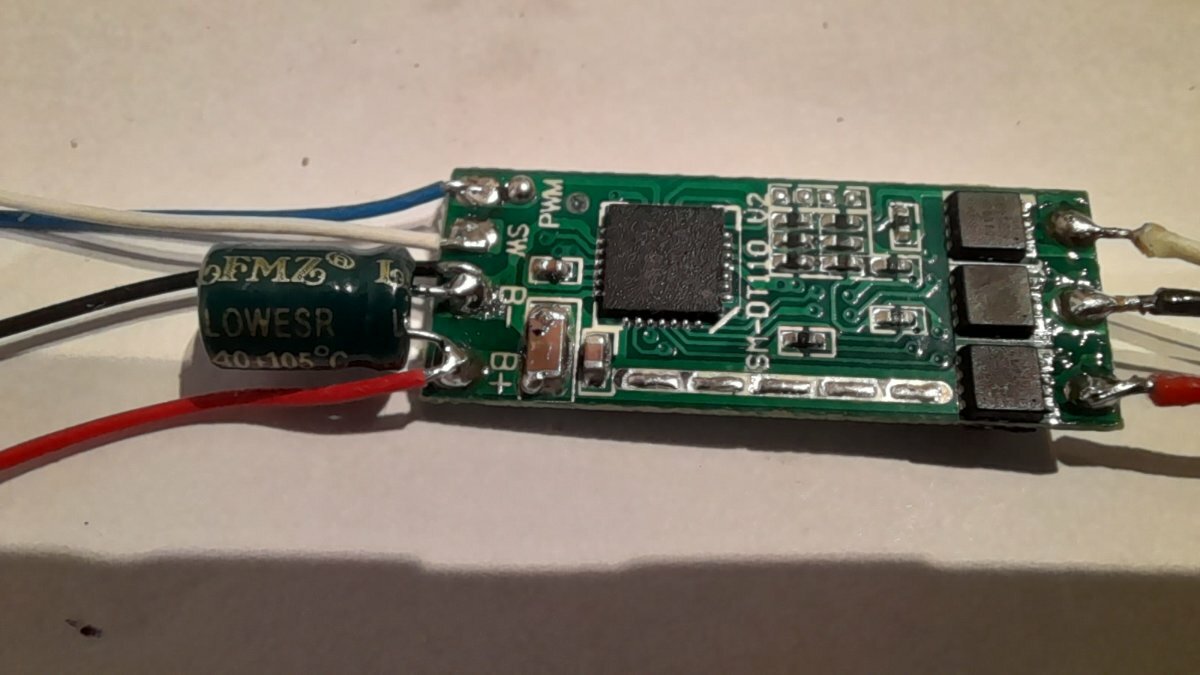
A signal from the receiver to a servo or esc would be a PWM signal, not a PPM signal. PPM used to be the input to the receiver in the 27 MHz and 35 MHz days , coming in via the antenna. Nowadays this is all digital transmission. So the blue wire would be the signal from the receiver, as it is indeed marked as PWM.
The red and black wires are most likely the power lines from the drive battery, providing the oomph to the motor via the ESC.
As for the BEC, it's unlikely that there is one, as that would mean that the supply to the motor would be the same voltage as that to the Rx.
So, hook up the black and red ones to the power supply for the motor, hook up the signal port (your channel 3, usually white or yellow, but blue in this case) at the Rx to the PWM pad , and hook up the ground connection on ch3 to the same pad as the black power wire. No connection from the Vcc of the Rx required (do not connect the red wire coming from your Rx to anything).
As for the SW pad, it's anyone's guess, but the link in RottenRows post seems to suggest that connecting it to Vcc (the red wire?) arms the ESC.
Max (everything above without guarantees, sorry).
Thanks for that Max, you've given me something good to work on there. I got this idea The red and black wires are most likely the power lines from the drive battery, providing the oomph to the motor via the ESC. It was indeed the signal bit I couldn't figure. I'll have another go later. Thanks.
I've just been making a start on repairing last nights storm damage to my garden fence. 90 mph wind gusts last night on the coast not far away from me. 😳
-
5 hours ago, Dale Bradly said:
Note the unit that RottenRow linked to specifically states "without BEC" so presumably Bonzo Moon's is the same
Yes, when I was searching for info on this I did see one advert that said without BEC. As you say Perhaps it’s intended to multi-motor applications where several ESCs would be installed and there would be no need for a BEC on each one. Like drones?
I'll have another play with it today! Thanks again for inputs guys.
-
50 minutes ago, RottenRow said:
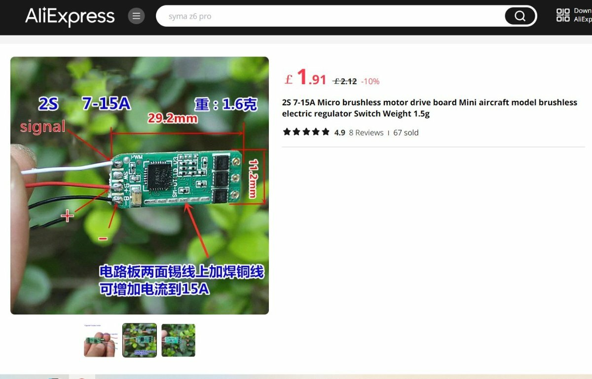
That's strange about the swapping over of the battery connections between different versions of the board, but it looks like yours is correct going by the B+ and B- markings on the board you have. If you look at the part number printed on the board, you will see that yours is V2 and the one in the Ali Express photo is V3. None of this is surprising for Chinese stuff!
Yes my suggestion for the correct way to connect it was as you have written. I was thinking that SW perhaps stood for switching regulator output. That SW pad doesn't appear to connect to anything on the front side of the board, but no doubt it does on the back, and it could be traced.
If you have a voltmeter, you can check between the SW and B- wires for 5V dc when the battery is connected. If you don't have a voltmeter a battery checker of the type used for flight batteries will do.
I have found another seemingly identical ESC here:
https://www.aliexpress.com/item/1005006113220552.html?
This one has a connection diagram, which shows the SW connection as being for a switch, with an odd description. Perhaps it's for an arming switch? If that is the case, perhaps the ESC doesn't have an inbuilt BEC at all, and you'll need to power the receiver via a separate 5V supply. Or perhaps it just another poor translation? Even this advert shows a mixture of V2 and V3 photos.
Without better data, all you can really do is experiment with it and see what you get.
Brian.
Thanks Brian, I appreciate the input! And yes, weird that that they'd switch something as important and + - power input ???
Think I'd trawled and seen the other pic in my searches too thanks.
I was curious about SW too?
Yes, basically I just experimented last time, nothing to lose at that price, and at the moment 92 mph wind gusts on the coast not far from me. Not much chance of flying for a while.
-
1 hour ago, RottenRow said:
The Ali Express photo shows battery positive (B+) as the second solder pad from the bottom and negative (B-) as the bottom one. Your red and black wires seem to be the other way around.
I would imagine the receiver PPM signal would go to the top solder pad, the +5V supply to the receiver on the next pad down, and the negative supply to the receiver on the bottom pad along with B-.
I would check the receiver voltage with a meter before connecting the ESC to a receiver to make sure it is correct.
If you have powered up the ESC with the battery connected backwards you might have damaged it.
Brian.
Well spotted Brian, I missed that, I went by what is actually on the board that was supplied. The sad thing is the Ali Express image is wrong! Can't trust these Chinese sellers. Check out this close up pic of mine which shows better the info on the small board. pos+ is actually opposite to their picture. (I'm an electronics engineer and I even checked if the electrolytic capacitor was connected the right way.) The power supply neg and the cap neg side were both on the neg on the board.
Their picture is wrong.
Those black and red leads power leads were presoldered and were correct when it arrived. I've killed things before with reverse polarity (you can't always rely on there being a diode for protection,) My power leads are correct with the info on the board.
Next pad down from the blue , ie white lead, is marked SW which I though would be the signal wire, ie no 3 on a BEC . Bec leads red, black, white or yellow.
But to clarify you suggest PPM signal, no 3 on the normal BEC would be on the top pad marked PWM, 5v ie red bec lead, on the one marked SW and the neg/ground on the input power supply black common ground?
But to clarify you suggest PPM signal, no 3 on the normal BEC would be on the top pad marked PWM, 5v ie red bec lead, on the one marked SW and the neg/ground on the input power supply black common ground?

-
KInd of bought this by mistake without noticing it wasn't like a 'normal' ESC with a power input side, 3 wires to a motor and a 5v BEC that would go on channel 3 on a receiver. I'm assuming the 3 terminals are to the brushless motor. Power is red and black and it shows signal on the white. But how do you connect to a receiver? I've tried using white and blue and a common ground on the black to rx but that didn't work?
It was only a couple of quid, though small and light and great for my lightweight foamie rc conversions so might be nice to get it working!
Any advice welcome please. .
-
Weather finally improved enough for me to maiden my first FMS Alpha jet cheap foamie rc conversion. My first attempt at converting a light foamy jet as opposed to the several+ Lidl foamies I've built. Flight went extremely well but a bit of a handful! Still needed a bit of trimming or maybe CG change and I'd be interested to hear opinions on what might have been wrong, (apart from my lack of piloting skills). My 1st thought was tail heavy, but as you'll see on the video it might have actually been nose heavy? Research says nose heavy? It was a bit of challenge to fly but came home in one piece and It'll be interesting to see if my CG change will make much difference next flight.
-
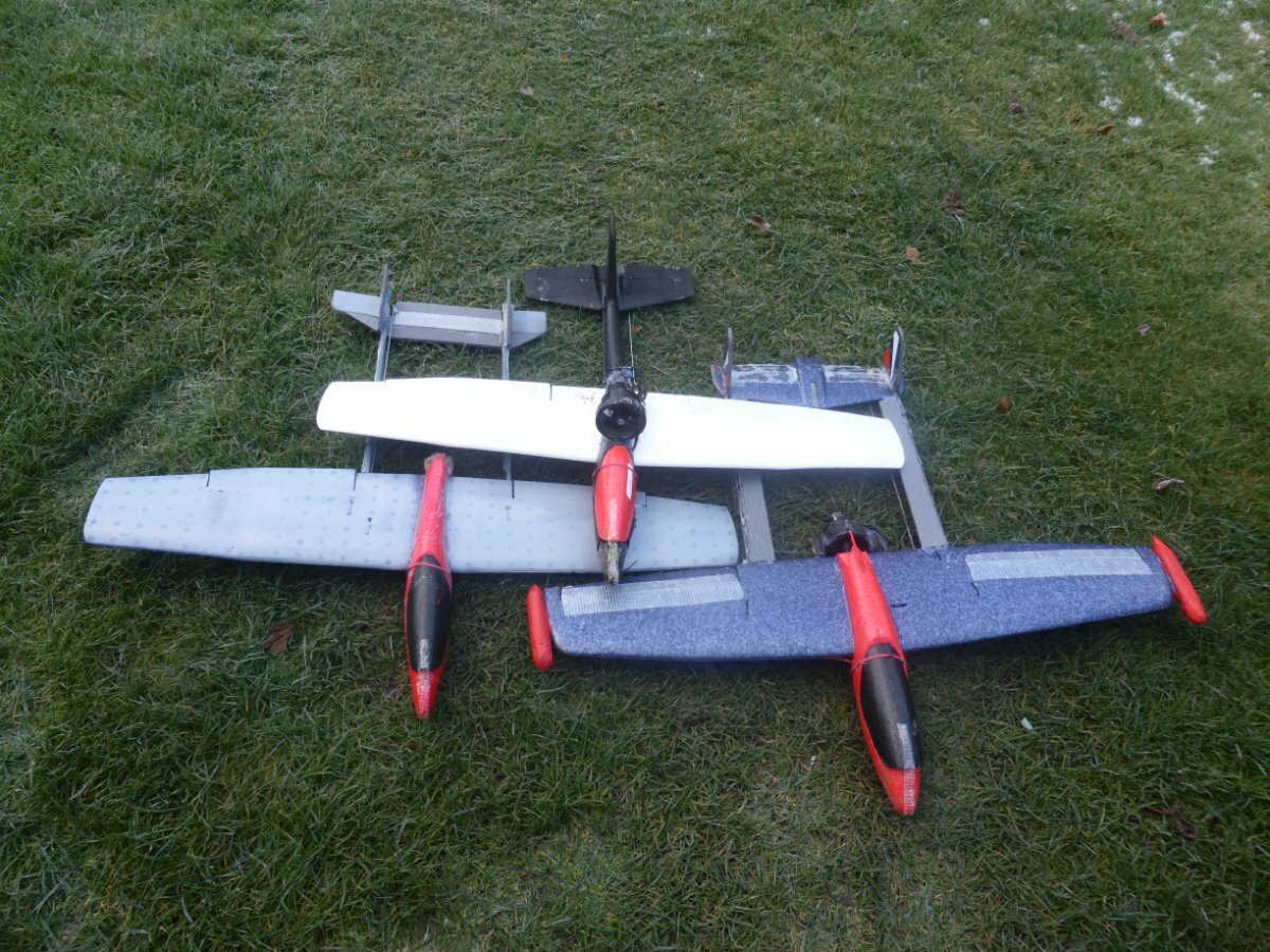
Well here it is, my Lidl RC conversion no 10, the Lidl 'Big Bird'. This is a kind of mini build blog. (I've already made full detailed build blogs on my channel.) Still have to decide which motor, probably BR 1806 which I've used successfully on a couple of my other Lidl RC's. I want to keep it as light as possible for slow flying, maybe FPV? Quite like the idea of a pusher with a pod on top, but I don't have a 3D printer and I've not had much previous success with my pushers. Anyhow, watch this space, more will follow. 🤨
-
A couple of months back I posted a video about a cheap little receiver I'd bought, FS2A 4CH AFHDS 2A Mini Compatible Receiver . Just around £6 delivered. The only downside is you have to solder the connector pins to the tiny little board. Soooo, here's a video showing how to do it and also how to bind it to a FlySky receiver. They are great for small lightweight builds, I've used a few of them and never had any issues with range. Another upside is they will even work with a 1s lipo.aliexpress link is in the video description
-
Seems like I was late to the party with this one as it was all over the forums 5 years ago, but here's my FMS Alpha Jet RC conversion. Plus another very small foamie jet I've also converted to RC. I was very pleased with my aileron and elevator solutions with the Alpha and no, I wasn't brave enough to go the EDF route with this one as I wanted to keep it light. Next time maybe ? 😉 The bubble canopy I made was in another YT video.You'll see in the video I'm wondering if it'll be underpowered with that little 1104 motor and a 2s and I might try it with a 3s 180mA if that is the case. It gets hot but I'm thinking as long as I go gentle and defo not full chat with it it should be OK? What do you think?Maidens for both will happen when we get a break in this awful weather! Plus the Lidl Mini foam biplane will get a 2nd test flight.HAPPY NEW YEAR!
-
 1
1
-
-
4 hours ago, SIMON CRAGG said:
Well done Bonzo, always enjoy your videos.
Happy Christmas and I hope Santa brings you something foam shaped!
Thanks Simon and Happy Xmas to you too mate!
I've still got one mini Lidl foamie, plus a big Lidl fusi and 2 big Lidl wings kicking around waiting for inspiration, so I'll have enough to do with those 😉
-
1 hour ago, FiddleSticks said:
Seen several videos of these little planes being converted to RC lately, must say I'm impressed as it certainly makes it even cheaper to get started in this hobby!
Incidentally they're not unique to Lidl, you can buy them in many places.
Always loved the innovation that goes with this hobby..
They are great fun to experiment with, and you learn a lot on the way!
-
1
-
-
Has anyone seen anything like this before? 🤣 My Mini Lidl Biplane foamie has a most unusual maiden!
-
A couple of weeks back I asked for suggestions for a build with a couple of cheapo small foamie gliders. WELL, HERE'S THE RESULT.The Mini Lidl Biplane! A quick build blog with a couple of useful building tips. I maidened today, which was 'interesting'? Video will be online as soon as I get a chance to edit it. Sub if you don't want to miss it 😉
-
2
-
 1
1
-
-
12 hours ago, Keith Billinge said:
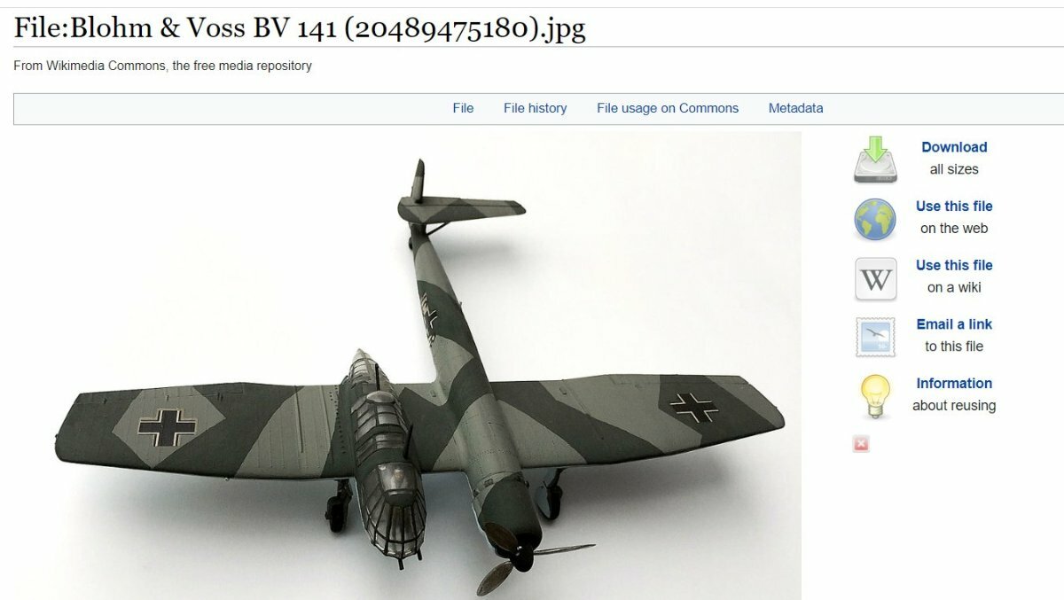
Blohm & Voss BV141
Must admit I had to Google that one!
That was an amazing design of it's time. Very strange.
The Blohm & Voss BV 141 was designed as a tactical reconnaissance aircraft. While passed over by the German Air Ministry for the Focke-Wulf Fw 189 Uhu, it became the better known of the two, due to its asymmetrical body. The aircraft’s unusual design made it appear as though it shouldn’t have been able to safely take to the air. However, tests showed it was able to fly without issue.
-
6 hours ago, john davidson 1 said:
As promised here is my flock .
Close up is the mount with scallop for EDF. Four scallops in all. A mite slower than expected maybe the efflux hits the tailplane so it might be better mounted higher.
The white winger is my original two years old at least and admired and copied by a couple of clubmates for its handling and speed.High EDF gives a downward on take off so I dial in up trim until at height.
Venom is very twitchy , perhaps too big ailerons so still working on rates
Pusher prop is also slower than expected, probably reason as above
White winger tail looks askew in photo? must check
Interesting selection... I've ony made one EDF big Lidl out of my 9 and that was top mounted simple design really but flies well.
Whereas my twin boom pusher still isn't flying well!
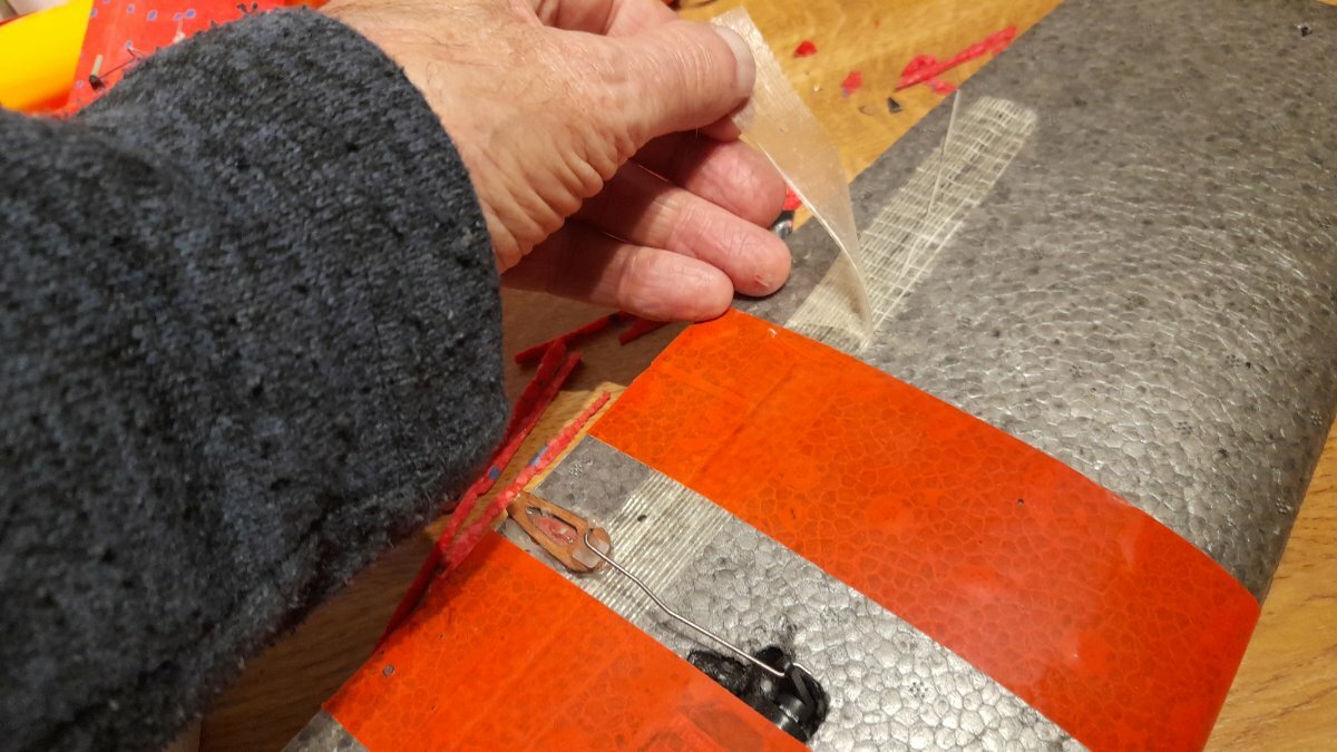
It looks like you have used the nylon reinforced tape to help secure ailerons on one model. Word of warning about that stuff! I did the same with my early LIdl conversions and after a couple of years it totally degrades and will just fall off! I had to go through a few models and replace it with Scotch Crystal tape which is everlasting!


Transforming a 'Dead' 3s Lipo into a viable 2s Lipo - Don't Discard it! - Step by step fix it video
in All Things Model Flying
Posted
Plugged into my charger and because one cell would not allow current to flow through it the power lead showed zero, charger said low battery, and didn't want to know?