

Nick Somerville
-
Posts
897 -
Joined
-
Last visited
-
Days Won
7
Content Type
Profiles
Forums
Blogs
Gallery
Calendar
Downloads
Posts posted by Nick Somerville
-
-
Majestic as ever, like all your models Chris. Still using the HQ wing section I see. Look forward to seeing it at the patch when the weather improves.
-
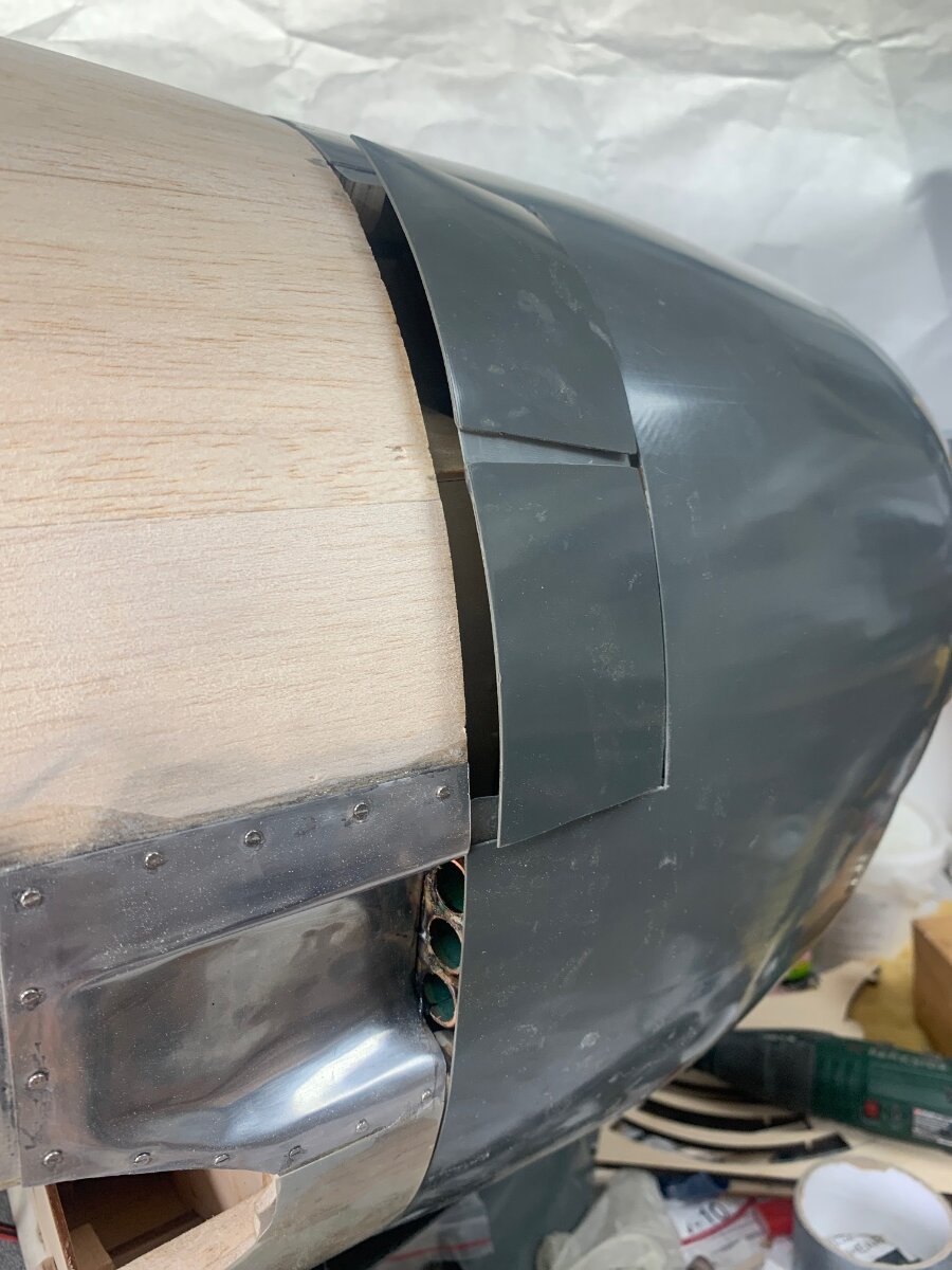
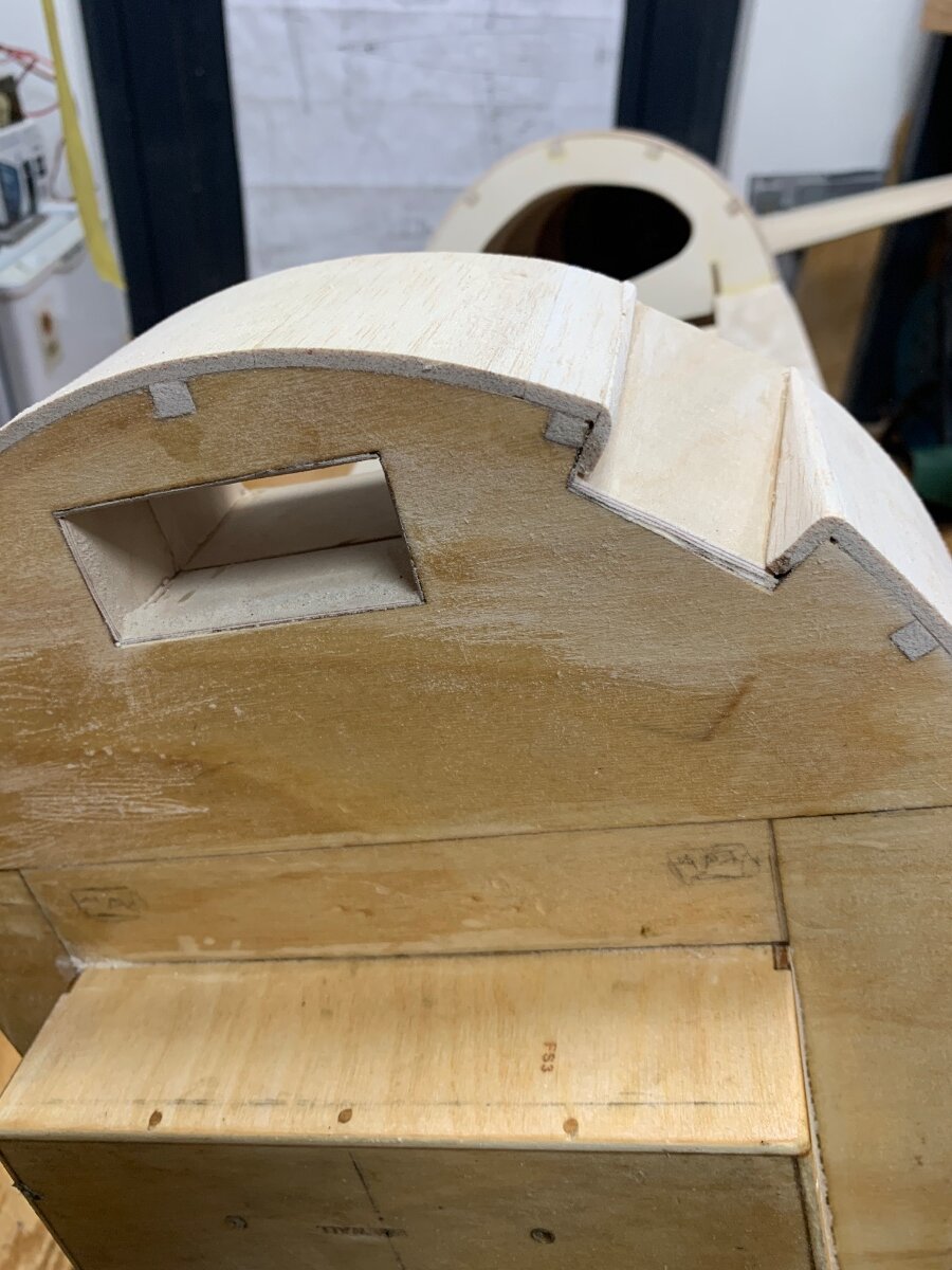
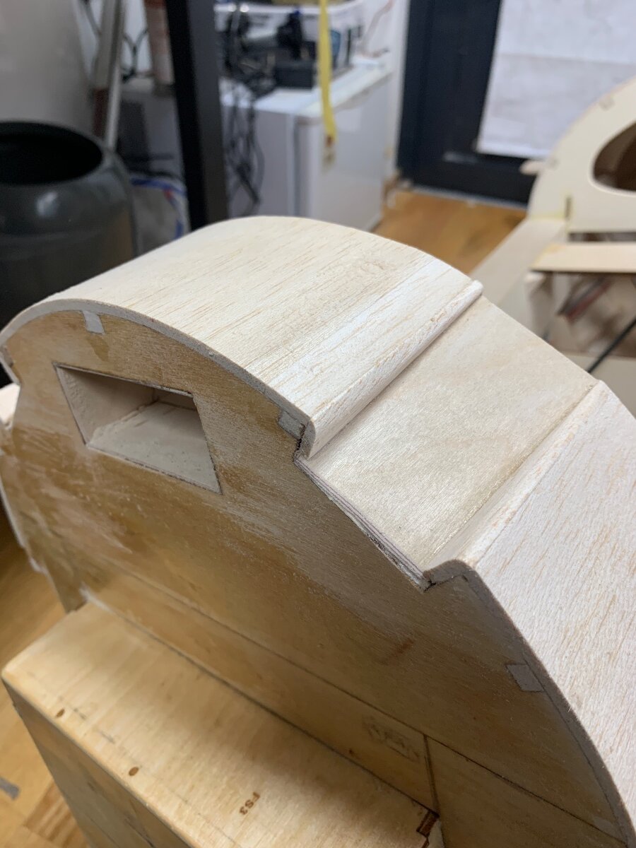
With weather awful I have spent the weekend spending far too much time fiddling with the cowl flaps. My intention had been to have them servo operated but in the end have accepted that the geometry for my plan was likely to result in some strain on the servo when either fully opening or closing the flaps, depending on the system employed. Ultimately I decided to have springs (bits of old fretsaw blades) keeping them open and a thin wire limiting the amount that they open. The pressure to close them is such that I am hoping that the prop wash and speed of the model at full chat should mostly close them, but at slower speeds the springs should hold them open.

Hinges are reclaimed from a deceased model.
I also added dummy exhaust stubs at the four ports.
-
 6
6
-
-
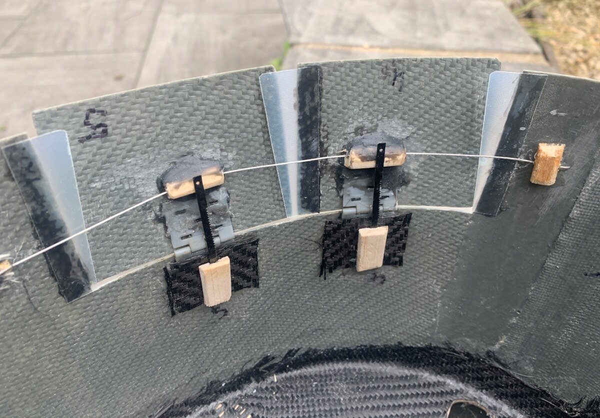
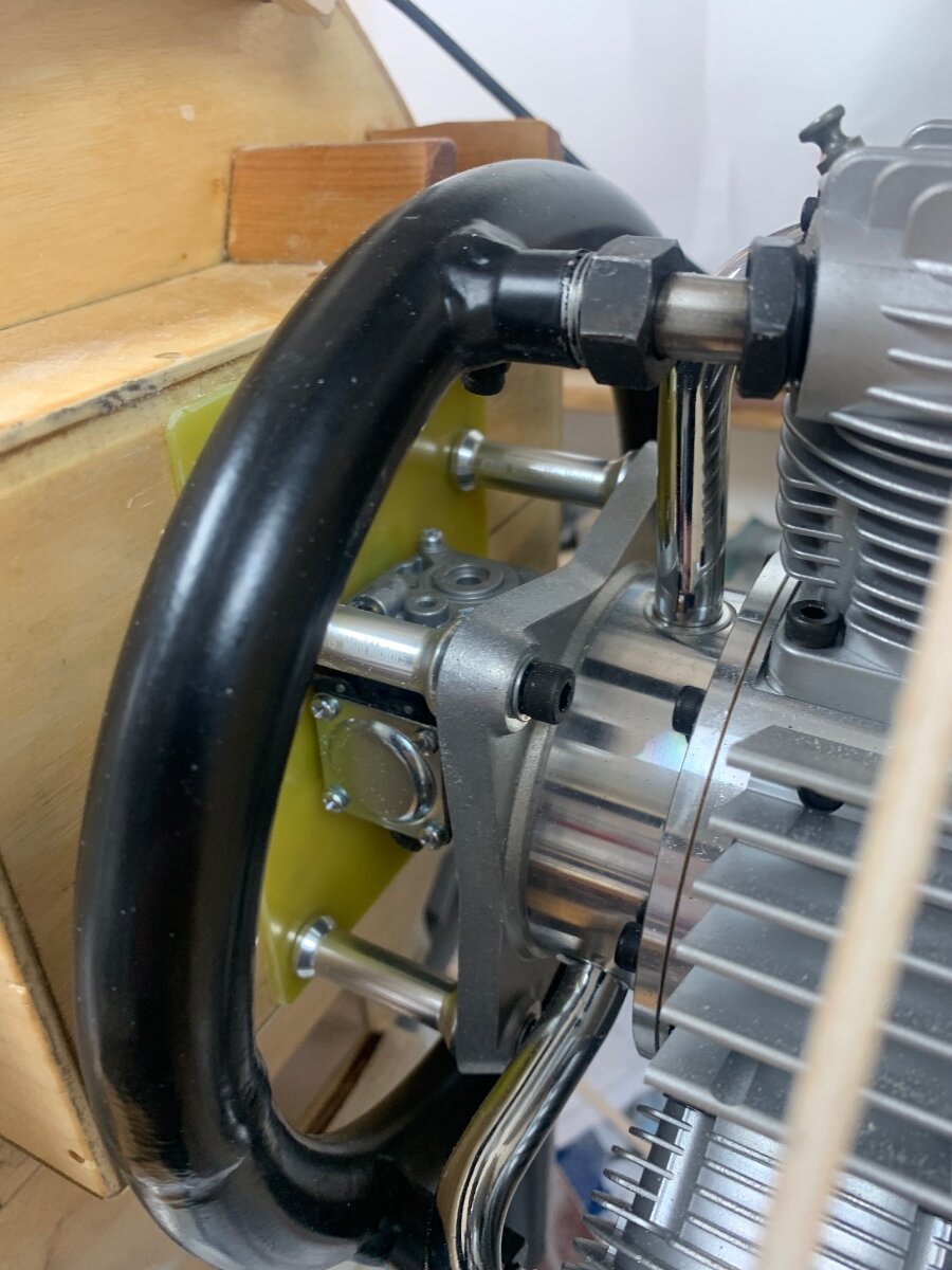
More work on the cowl. To my horror when mounting the engine for the first time I found that my ‘careful’ calculations where some way off and the engine was sitting 12mm too high. In my defence the plans for the engine box area just don’t match some of the parts and to an extent I have had to wing it a bit in this crucial area. Additionally the prop hub was 3mm behind the cowl lip.
In the event 12mm was so much better than a few mm as I was able to drill new holes and add new captive nuts behind the firewall avoiding the originals. A 3mm G10 plate was added and new apertures cut for the fuel line and carb.
The four parts for the cowl edge to slip over and place have been glued and screwed against F1, each with a pair of magnets imbedded. Their twin counterparts will be glued to the cowl. I am hopefully that the combined strength of 16 10mm neodymium magnets will hold the cowl in place without the need for any bolts. We shall see!
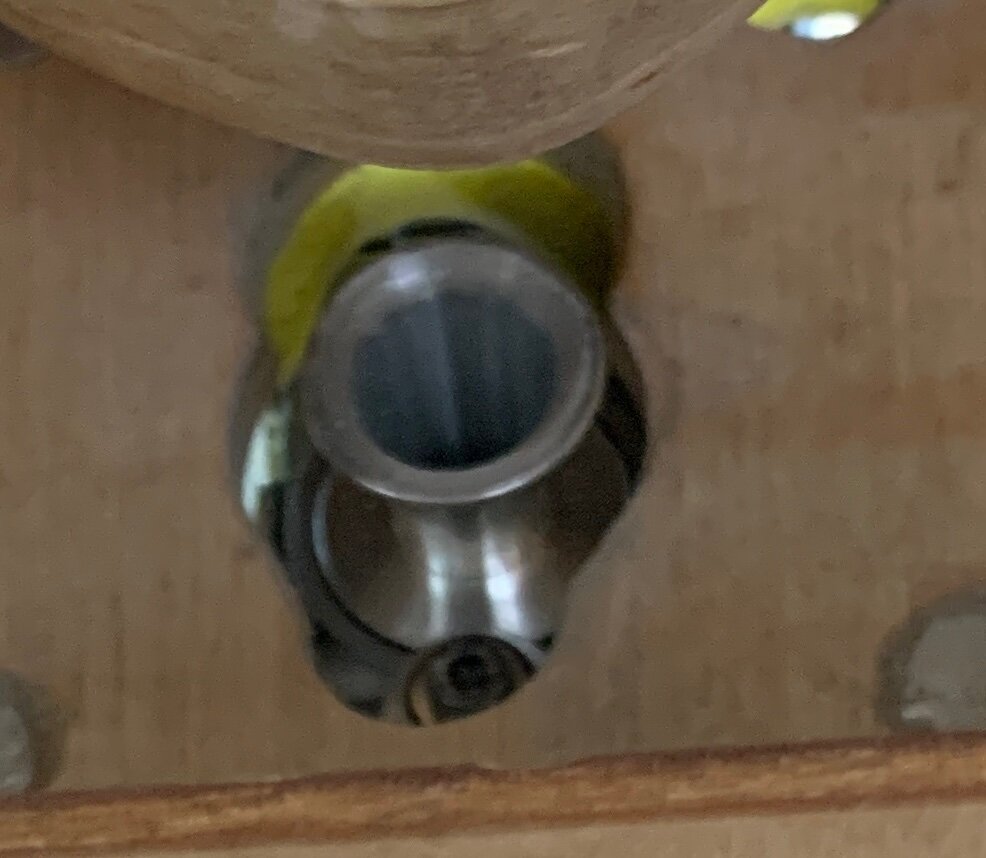
An additional benefit of the G10 is the spreading of load where the 40mm stand off’s press against the firewall. You can see here the carb almost flush to the plate and the Venturi is well inside the fuselage.
Once the engine is permanently mounted I shall seal around the sides of the Venturi with foam rubber so it can only draw cool air from inside the fuselage.
Engine temporarily mounted.
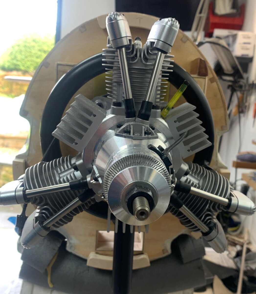
I took a front view of the engine from the Saito website and printed it out actual size. This was cut out and traced onto light ply and fretted out for the baffle plate. The clearance is between 1-2mm around the engine but until it is glued to the cowl I won’t be able to make any final adjustments. I should think 2mm will be ideal all around to keep the airflow close to the fins but not so close I start a fire.
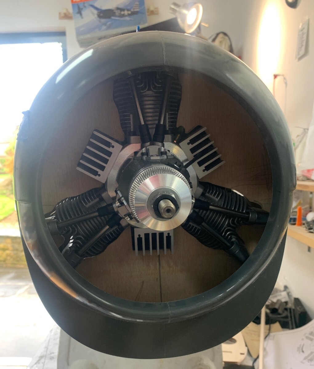
Here with the cowl in place. Note the lower cowl cheek still to be added and the air passage opened.
-
5
-
-
Thanks for thoughts chaps.
My Spektrum Life batteries are not the Smart type. My Overlander D100 V2 doesn’t baulk at charging 2 Lipos at the same time or 2 Liions! Interesting point about the earthing though. I did have an earlier D100 without the voice prompts but that went bang when charging the same life batteries simultaneously. Quite scary as I was working close by at the time. Interestingly if I go down to 0.5 amp charging it does sometimes behave.
Interesting comment about Liion batteries being no better than LiPo. If you google LiIon the blurb always comes up as superior to Lipo on several fronts. Also Powerbox and Jeti, both high end radios, market them as preferred Rx and ignition batteries. I assume there must be a reason.
-
I have pairs of Spektrum Life receiver batteries in two of my warbirds and they infuriate me. If I try to charge them simultaneously on the A & B ports on my Overlander V2 charger 9 times out of 10 I get a Bad connection warning. If I charge them one at a time they are usually ok. As mentioned the flat discharge means you never really know what capacity they have left. I chose them because of the reputable brand and fact that Life batteries can be charged in the model, unlike Lipo’s and warbirds generally have batteries tucked away up front within the cowl area as ballast.
To add a battery type to the opening question, what about LiIon? I put three in my FW190 (2 x receiver and 1 for ignition). So far I have been happy with the choice as they are simple to charge and can stay in the model, though not so re the cost.
-
Yes read that about the canopy. Could you carve up a plug in one piece and ask Phil at Fighteraces to pull one for you? Supplies for large models are increasingly hard to come by. I was so lucky that after a three month wait I got my Hellcat retracts weeks before Robart made their announcement.
-
Getting close Craig! The wing root fillets came out beautifully! How much detailing are you planing for the surfaces and cockpit?
-
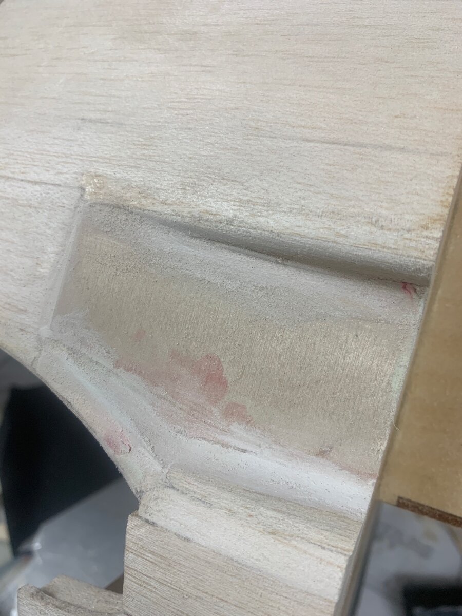
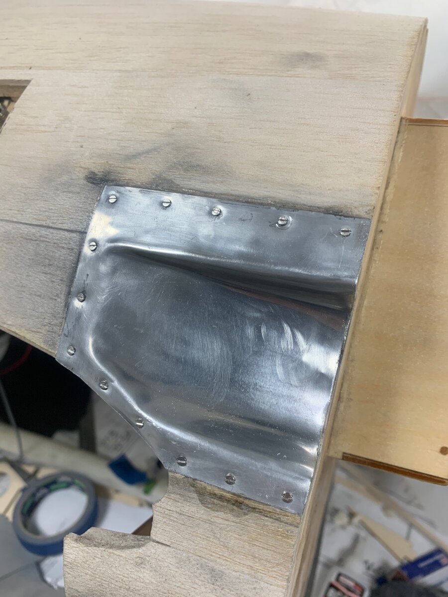
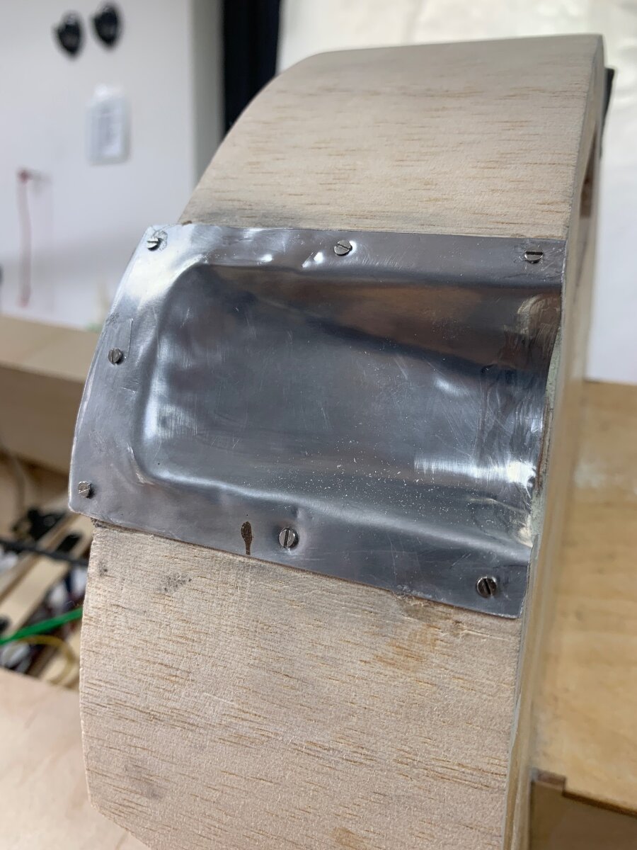
Some work on the four exhaust outlets. Also the forward part of a hot cowl air escape passage that will exit at the lower underwing oil cooler flap.
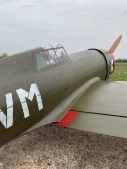
The Minsi lll colour scheme I am planning has the exhaust outlets unpainted, giving a nice contrast between the dark blue and shiny aluminium. Bit like my Sea Fury.
The litho needed a good blow over with a blowtorch to soften it prior to working it into the recess.
-
2
-
-
Wishing you all the best Jon. I shall miss your helpful advice, knowledge and the engines. My Lasers will be treated with extra reverence henceforth!
-
2
-
-
After a second attempt the carbon laminated tailwheel cover did finally cure. Following a chat with a chap at Easy Composites I am going to start using a 50:50 mix of the fast and slow EL2 hardener in future, to achieve a better balance of pot-life and curing time.
Another tip from Easy Composites is that they now sell structural thixotropic epoxy adhesive similar to the very expensive Hysol. 1/3 the price so I shall be trying some out for the various in cowl fixings and will report back.
Here the cover is in place.
Here in the deployed position the brass mounting parts can be seem. These are epoxied to the cover and 3mm bolts fix them to the retract chassis in tapped holes. Lightweight but definitely long grass resistant.
Next I need to remove the wheel yoke and reshape it from its Corsair looking iform to something resembling a F6F fork.
-
4
-
-
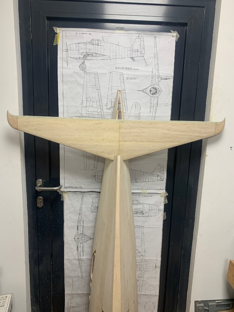
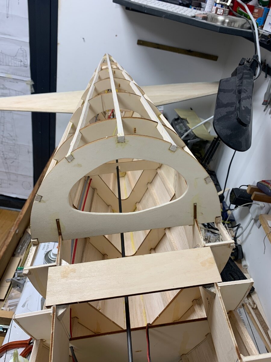
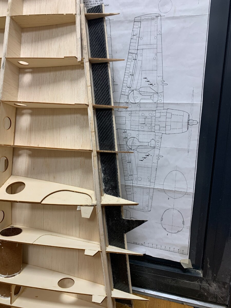
A dry day at last so a chance to get outside to fine sand the fuselage. I am leaving the last rounding of the spine until later as it will inevitably get hangar rash if I do it now.
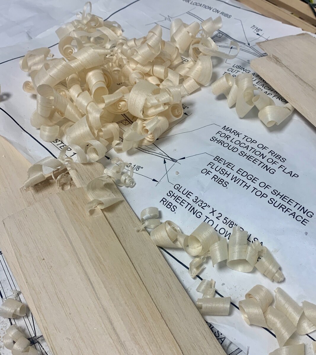
I had a seemingly huge pile off 3”&4” 1/8 balsa of 36” & 48” lengths when I started the build. I always go over the plans and try to carefully calculate all my needs at the outset, but nevertheless this time I had come to a conclusion that I had seriously over ordered. Left to skin are the wing undersides and the belly pan. On a fresh count it seems there probably won’t be a full sheet left when I finish after all.
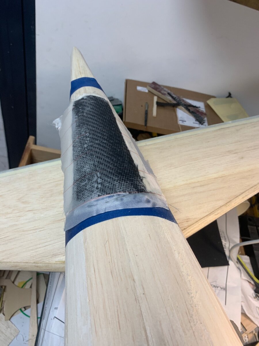
The carbon I had laid up over 24 hrs ago seems very slow to fully cure, so perhaps a misjudgment when weighing out the proportions. It’s tricky when mixing such small quantities, even with digital micro scales. Hopefully it will harden eventually, just need to be patient.
-
Plastic coated 50lbs wire fishing trace arrived this morning from an EBAY seller. 20m for £3.40 including crimps and postage (not everything in modelling is expensive!). With the the pair of closed loop wires threaded through the guides and the ends carefully taped together so they don’t get lost, further progress was enabled. All of the fuselage excluding the small area forward of the wing has now been sheeted. I have a small hand held Hoover steam cleaner I bought for the household some years ago and it’s ridiculously slow and totally unfit for purpose. However, for steaming sheets of balsa it’s a very useful accessory. The sheer bulk of it is now very evident and I considered listening to some whale song in the workshop as fettled away.
Final job of the day was to tape down plastic sheet over the tail retract area and smear it with some wax polish. Next I wetted out some carbon cloth followed by a layer of lightweight glass cloth. Finally a layer of peel ply to soak up any excess
resin and then all taped down with masking tape.
-
2
-
-
Yes quite snug Paul, but cam be opened out once the skins are in place and the scale size openings are established.
Fuselage went back on the jig to glue in the stab. This has been glassed and cut back smooth already as harder to do later. Epoxy and micro balloon mix on the saddle and two strips of carbon cloth on the inside to reinforce.
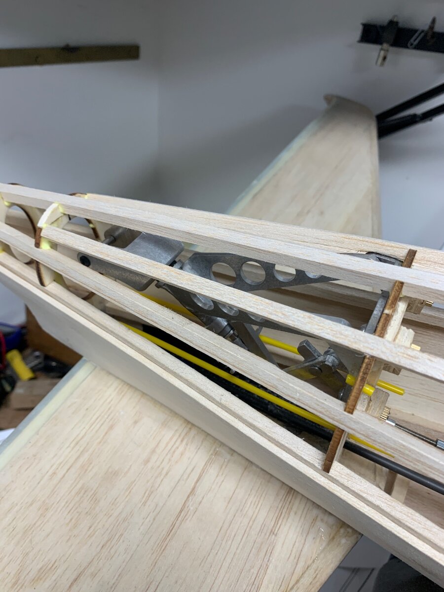
Lower rear formers and stringers now added. Carbon push rod for elevator in place. Note guide hole in added cross member mid distance, to prevent any bowing when pushing for hard up elevator.
At the rear the tail retract was mounted prior to adding stringers to ensure I had the travel to completely hide the wheel. Outer snake guides in place for rudder and tailwheel closed loops.
All the above proved very straightforward but the front end between the cowl and the wing leading edge is a different story. Neither of the key 1/4” ply lower formers, although correct to the plan, fit anywhere near to the correct position. I suspect I shall need to remake these parts.
-
1
-
-
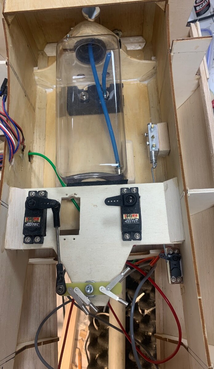
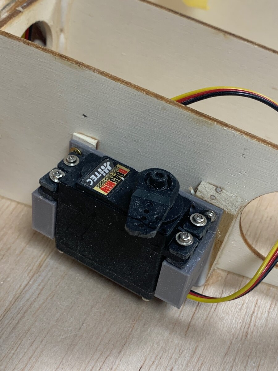
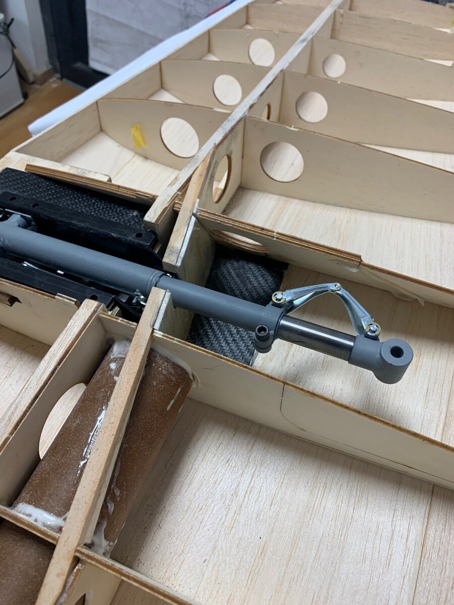
Some work on the fuselage while waiting delivery on my wheels. Tank fixings sorted, tail retract and pneumatic cylinder placed, elevator and rudder servos mounted. Also the air valve and activating servo mounted. The rudder servo will be using close loops for both the rudder and tailwheel steering and so have made a sturdy bellcrank for these to take the pressure off the servo.
Wheels arrived (5 1/2” Robart tyres on scale Sierra hubs) so have been able to finalise the hatch position for the inner flap servo. I have made up 1/32 balsa wheel well liners with an extra 1/32 strip around the top edge. This will provide good support for the lower skin.
This leaves little left to do before I can skin the underside. Mostly checking all the rib and spar levels and checking how I am going to create access to the retracts for servicing.
-
Wings starting to fill up now. The aileron and outer flap servos are mounted on their sides in 3d printed mounts. And the inner flap servos vertically in the same type of mount.
Pneumatic lines installed along with the first servo extension lead. Once the others are in place I can neaten up with some tie back clips.
Hatches will be cut after sheeting and retained with a tongue on the forward side and a small magnet at the rear. A small hole in the hatch will provide a pry point to release it.
inner flap servo yet to have access sorted as waiting on delivery of wheels. Once these are in hand I can see what space is like around the wells.
-
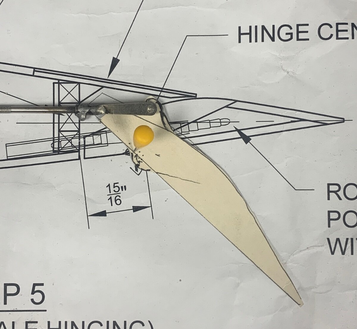
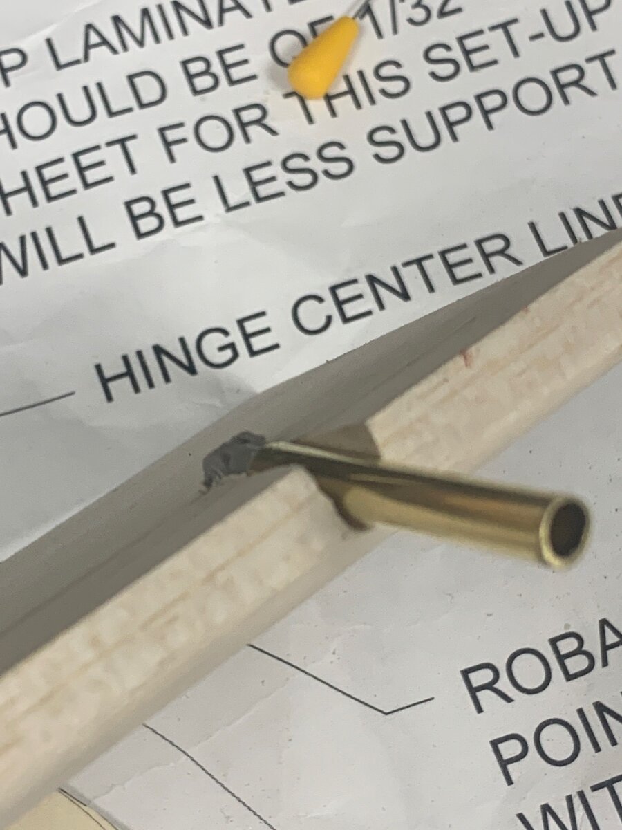
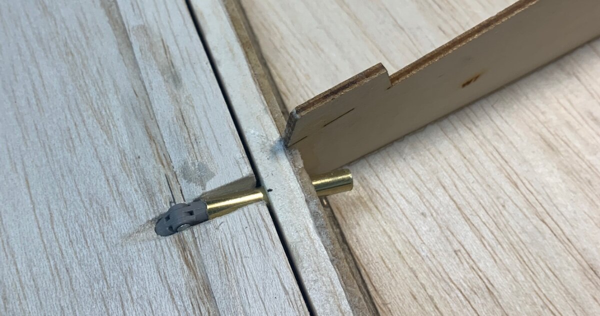
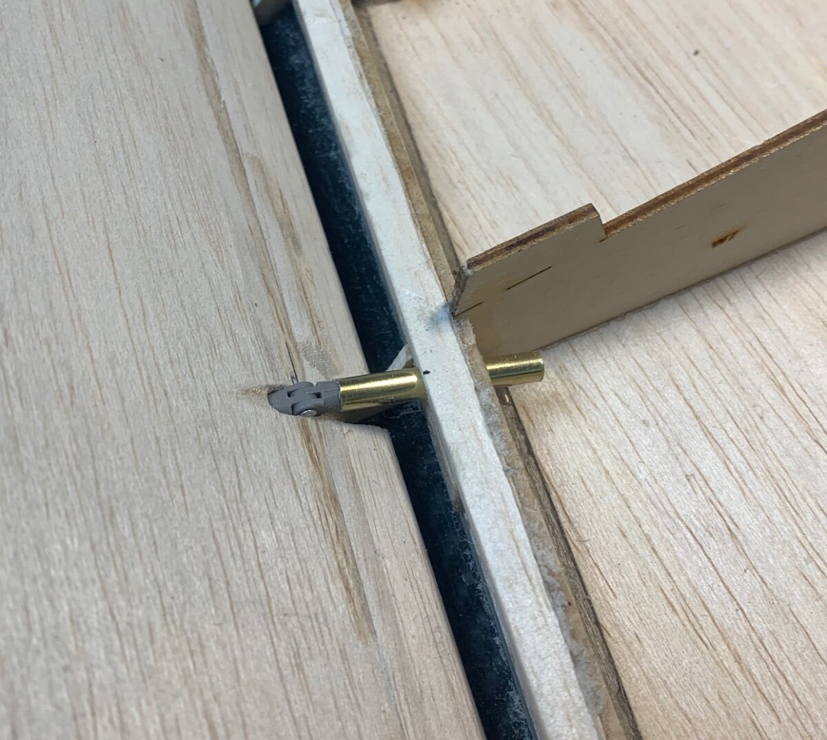
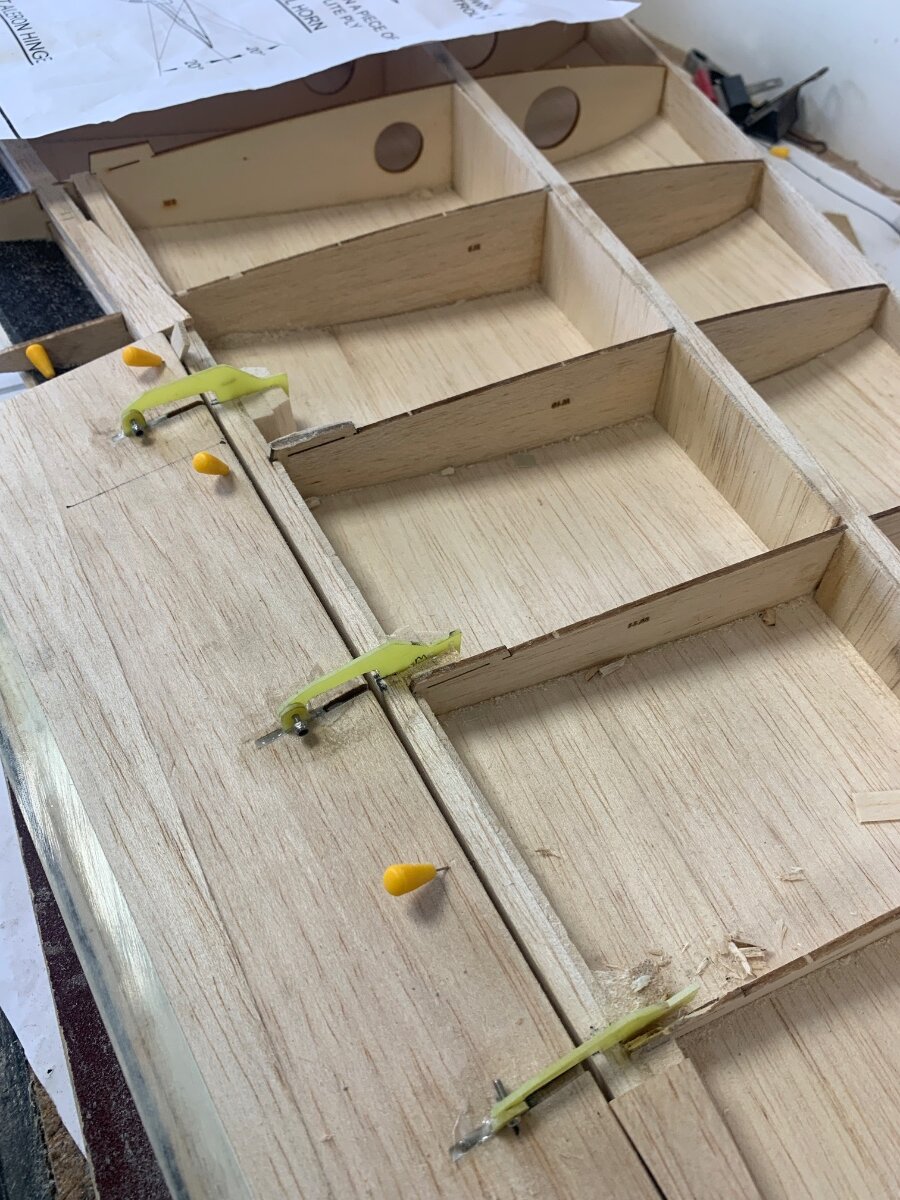
Using a card profile of the flap section over the plan to check hidden horn placement and hinge action. The plan showed two possible versions and I have made a compromise between them with a closer to scale action during deployment.
The brass tube gives additional support to the Robart hinges where they extend 20mm from the rear spars. A little more local balsa blocking will fully secure them once they are all glued in place.
Flap closed
Flap at 60 degrees -
Nothing to see really except for the joy of a sharp blade in a razor plane. Been working on the outer flaps.
-
1
-
-
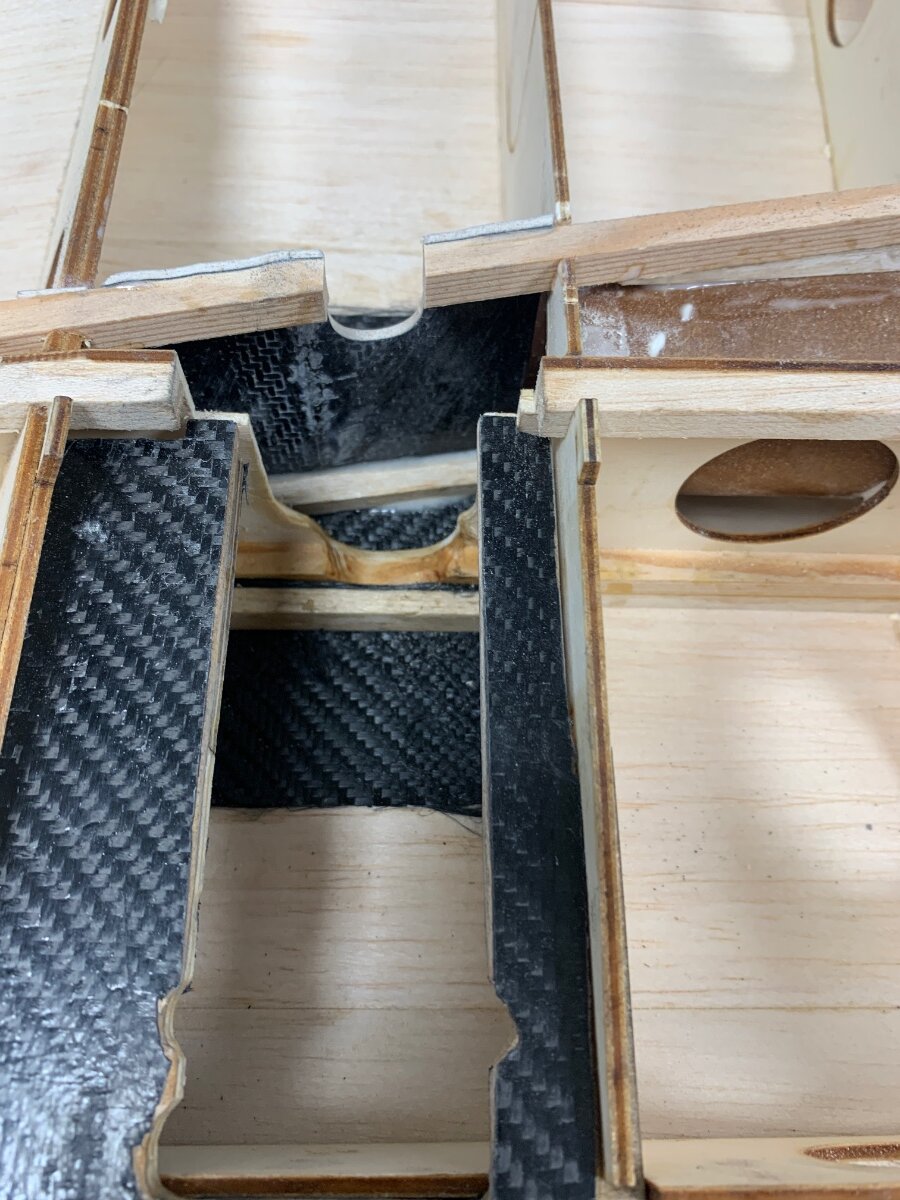
Strength regained!The balsa cross piece in front of the upper spar, where I had removed so much of its thickness was to aid pressing in straight wetted out carbon tows for reinforcement. The ply mount plate for the gear was not especially good quality and with bolts close to the edges I felt it worth laminating a layer of carbon cloth on each side. I shan’t glue these in until I have the wheels in hand as I need to check how it all sits with the wing under surface.
Although the lower spar is still cut through, the combination of the new spar and web along with the bridge of the retract when bolted in should be more than adequate.
The webbing for the new diagonal is left over balsa carbon laminate I had made for the flap shrouds. Light and stiff. In fact all the additional parts came to about 35grms per side, which as its about on the C of G I won’t be losing sleep over.
-
1
-
-
Aileron ligned up and pinned in place while the mix of epoxy and micro balloons sets the hinge arms in place. After all hardened off it was satisfying to find a friction free movement with snug fit close to the upper shroud.
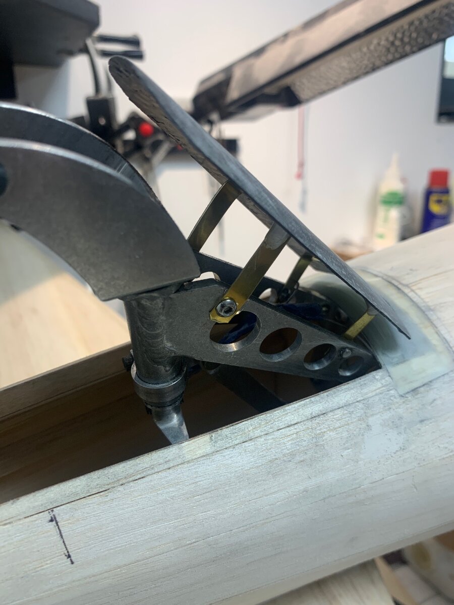
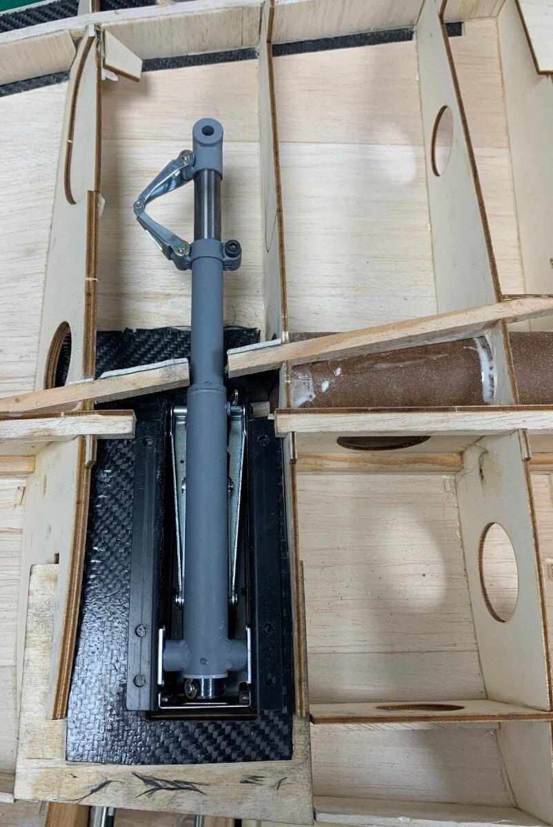
Mt Robart mains finally arrived last week from the states having ordered them back in October. It was the lack of stock of tail retracts that was holding things up so I deleted that from my order and four days later the mains arrived. Very nice BUT!!!
So the length of the units and in particular the depth due to the cylinder meant they just don’t fit without major surgery.
Here you cam see the modellers nightmare where I have had to cut out a huge amount of the ply shear web/dihedral/brace and also sand away 50% of the upper spar to leave very little strength at all. The carbon is sitting there awaiting resin and a host of other parts I have fabricated to regain the integrity such that won’t be afraid to loop the model at a decent speed. The saving grace is the wing joiner tube from where The real load originates. More pics soon which will show my solution and the size of the problem (The retracts)
Oh and for the tail retract I have recently acquired a full pack of bits for a Bates 1/5 Bearcat including Sierra retracts. As the tail retract is the same for the Hellcat I shall use that, since the Bearcat will be on a shelf for a couple of years.
-
1
-
-
Great maiden. 14kg is a very good weight for the model. Mine is 16kg but still not heavy for the wings area.
-
Martin’s beautiful book on The Worlds Vintage Sailplanes was like a bible to me back in my scale glider modelling years.
-
So true. I used to cut these parts with my fretsaw but it ate blades for a passtime and I hate it when they break when cutting. Drilling and filing is tedious but preferable. Thanks for the encouragement.
-
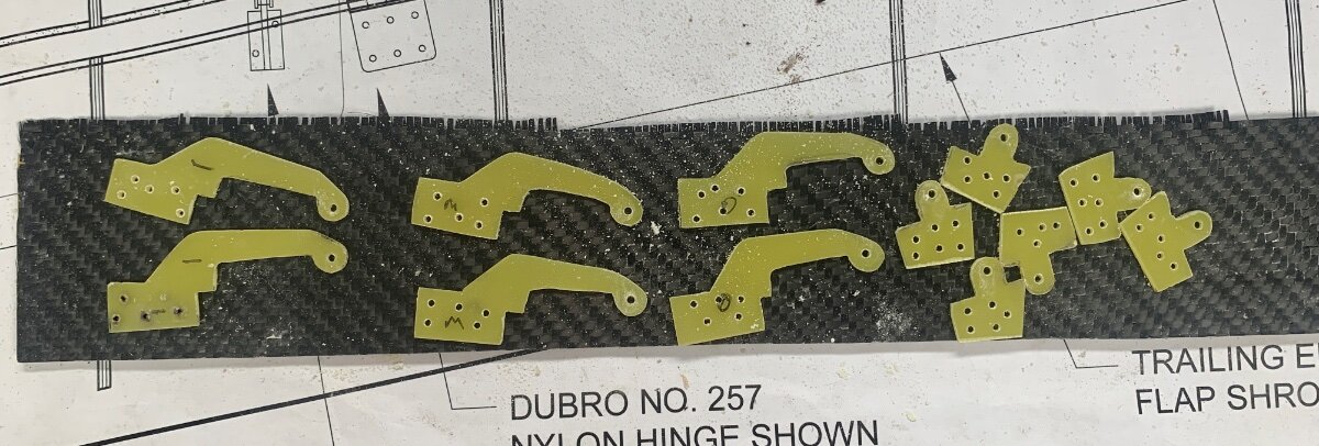
Aileron hinges in the lasercut parts kit were ply and not durable enough, so 2mm glass fibre sheet has been employed. After marking out a dremel was used to drill around the shapes few drilling and then they were sanded and filed to shape. One if those tasks that you inky want to do once in a while!
-
1
-
-
I have been a bit confused (usual) regards the flap construction and although the upper shroud is now in place I have made a start on the ailerons whilst the brain fathoms the flaps.
Here’s one of them. Pretty straightforward but as the full size had fabric covered ailerons it’s a bit of a work around. Sheet underside for rigidity and a laminated trailing edge with carbon tow inset and a 1cms strip of G10 below. Nice and stiff. I can simulate the rib stitching and pinking strips on both sides once covered, though the upper side will be more realistic. Still to add are the reinforcements for the hinges.
Below are the upper and lower wing areas with the flap shrouds. As previously mentioned this is a G10/balsa/carbon laminate to cope with the large overhang.
-
2
-


Jerry Bates 1/5th Hellcat
in Scale Matters
Posted
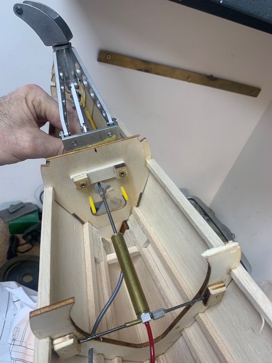
It’s always a relief to finalise hingeing and actuating linkages for flying surfaces, especially when it is all hidden. I can only hope the flaps and ailerons work out as well as these tail surfaces have. I have installed a carbon pushrod to the elevator and closed loop to the rudder. Nice and smooth/slop free with everything lined up as it should. The elevator and rudder trim tabs have been fabricated from G10 with carved chemiwood dummy actuators.
The patchy grey areas are where I have primed inside the shrouds as they won’t be easy to get to later. On previous models I painted the elevators and rudder separately and then fitted them. However for this model they had to be installed first.
When shaping the forward fillet for the fin I found I had an unwanted hollow at the forward part and had to resort to a skim of lightweight filler to blend things in. A final shaping of the rear spine and a good sand all over and the fuselage will just about be ready for glassing. I haven’t decided though whether to cut the rear windows before or after glassing.