

Nick Somerville
-
Posts
913 -
Joined
-
Last visited
-
Days Won
7
3 Followers


Recent Profile Visitors
2,849 profile views


Nick Somerville's Achievements
659
Reputation
-
Operation of the forward gear door now sorted. A small appendage on the inside of the door is pushed by the forward moving centre cover part. To close the door a length of shirring elastic attached to it has been routed down and around the leg pivot and fastened to the rear of the gear chassis. The shape of the appendage came from trial and error. It has a rather small space to drop into and I lost count of how many versions I tried before achieving a satisfactory operation.
-
the moulded leg covers have been separated into the three parts. The forward parts have been hinged to open down/forwards, the middle part has been glued to the non rotating upper part of the strut and the main lower part attached to the rotating lower strut. The collars are a simple brass strap and shaped Chemiwood spacer glued and screwed. The cover is screwed to the spacer block with rubber servo grommets in between to allow small adjustment to achieve a perfect fit and to provide some shock absorption. I added a strip of 1/8th sheet balsa to stiffen the lower cover. Still working on the best way to open and close the forward door part.
-
Hello Glenn, I haven’t really given this to much thought yet. The only part that seemed heavy was the elevator, which isn’t ideal of course. The fuselage and wings feel a little lighter than my FW190 so I am guessing she will be around 17kg ready to fly. I will weigh the component parts soon and report back.
-
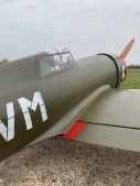
After a bit more fettling the first coat of primer has been sprayed. I like this stage, so long as the surface imperfections aren’t too excessive, as it heralds the start of the detailing. First most of the primer will be rubbed back with 400grit and then panel lines access hatches etc. added along with rather a lot of raised rivets. Next more primer along the panel line areas and then flush rivets burnt in. Apologies for the mug shot spoiling the lines my Hellcat, but it does give perspective to the size. Definitely a chubs, but soo much wing area.
-
So this is the radiator outlet that I have been working on as part of the removable belly pan. The pan has now been glassed and a radiator deflector part made up from .5mm aluminium sheet. As the magnets won’t keep the pan in place following the bump on landing I have made up a linkage from the deflector to a locking pin. It’s spring loaded so the deflector stays in the semi lowered position and when pulled down a little the pin is withdrawn.
-
Belly pan sheeted and hot air duct fabricated. The rear screw is temporary to pull it away from the magnets. They are quite strong, though there will be a hidden catch to stop it dropping off when landing heavily (not uncommon for me). The forward portion of the duct has a hinged cover yet to be made. Looking down the duct. The hot air duct from the inside. So that’s it for the balsa bashing on my Hellcat. Summer has finally arrived here so its flying time for my other models!
-
Wings and fuselage now glassed. Still needs a good rub back and a second coat of resin but have found that this is best done several days after the initial application, so the resin is fully cured. 45grm cloth (sourced cheaply from ebay) and Easy Composites resin. As it continues to rain and blow in these parts I am pressing on with the last of building for my Hellcat. As I have constructed a two piece wing the belly pan needs to be removable; a benefit being it will hide the wing fixing bolts. The formers have been temporarily double sided taped to the wing and at the rear two pairs of neodymium magnets set on the wings and rear former will hold the pan in place. The front former has a rectangular aperture, matching the hot air exit duct from the cowl. A further duct inside the belly pan when added will exit at the oil cooler flap.
-
Thanks for the heads up on pricing Ron. Got my order in for 5 gallons which should keep me sweet for a while.
-
After measuring dozens of times to ensure correct alignment the front locating dowels have been fitted along with the rear hold down bolts. With that milestone completed I just had to pop the retracts in place and get her on her wheels for some photos.
-
Thanks Ron. Can’t take credit for the design. Fine scale modellers Simon Lawson and Steve Rickett both demonstrated this method on their Bates and Zirolli Hellcat builds. It does work well and is so much neater than the four screws employed on the servo hatch covers on my other models.
-
Wings now almost completed ready for glassing. Inboard flaps fabricated, LE and tips added and shaped. Just need to make the final fettling for the wing to fuselage mating and addition of locating dowels and securing bolts. the six servo hatches were cut out with a fresh blade, skinned with 0.6mm G10 for durability and lightly sanded on the inner surface for a flush fit. A neodymium magnet and tongue holds them firmly in place. A piece of thin wire is inserted into a tiny hole for removal. Hopefully barely noticeable after painting.
-
The first set of covers had to be binned as I had made the blister mould forms actual size and by the time the carbon cloth had formed around them, they ended up about 3mm too big all round. Also there was some lifting from the flatter wing surface parts during curing. I re sanded the balsa forms until they were 2-3mm smaller all round and after laying up the cloth as before I covered with a further layer of ‘Peel Ply’ and then weighted everything down with freezer bags filled with sand. The trimmed parts are strong but have sufficient flex to absorb knocks and weigh just 25grms each. Pretty pleased with the result that conform to the wing profile perfectly.
-
Hello Mike I will try to outline the key costs, but bear in mind the choice of engine and radio gear has a huge impact. In my case the Saito FG90 is twice the cost of say a Zenoa 80gt twin. Plans, laser cut parts and additional wood for the Hellcat was about £500-£600. Retracts and wheels plus pneumatic components £700. Glue, paint, resin other parts £150. So realistically it’s around £1500 without the radio and engine. It’s likely to be a 20 month project so £75 a month for the airframe. I consider it great value as I enjoy all the hours of building. My previous build (Vailly 1/4.5 FW190) was cheaper as I bought plans, wood and retracts from someone who had decided not to build the model. Also my next build will be a 1/5 Bates Bearcat, for which I have bought everything needed at half price; again from someone who decided not to build it. So if you are put off by the cost but really want to have a go at a large model, there are some great bargains to look out for. Regards staying power: my advice is only ever build one model at a time and always finish it. I always have maintenance and repairs to carry out to keep my other models airworthy in any case and have a small workshop too.
-
With the lower wing skinned I haveshaped up a pair of leg cover blisters from some 1/2” soft balsa. In this photo one has been covered in heat shrink fabric (don’t have any film). The leg area of the wing had some waxed paper taped over and the blister double sided taped in position. With the whole area lightly smeared with some car wax 2 layers of carbon cloth and a layer of 48grm glass cloth were layered over and wetted out with Easy Composites resin. A vacuum bag would have really helped keep everything flat and compacted but as I don’t have this equipment it was a matter of keep checking as it cured and some pins where there was some lifting.
-
. Looks like fashioning shapes from it will be a trial though. Hello Nigel, nice to following from New Zealand. As mentioned in my build notes, I have found for small parts multiple holes with a fine drill on a dremel works for me. I was visiting a clubmate the other day and he uses a fine blade in a small bandsaw works for himself. Carbon plate too up to 4mm thick


