

Richard Leech 3
-
Posts
60 -
Joined
-
Last visited
-
Days Won
1
Content Type
Profiles
Forums
Blogs
Gallery
Calendar
Downloads
Everything posted by Richard Leech 3
-
 The remaining of the build was per plan, the lower wing strut attachment was made using a piece of 0.25"x0.064" brass strip which ran through the fuselage and glued to F4. I also added a gyro for those windy days if needed. The CofG ,AUW and ranges were as per drawing, I used a 4S 3300mah battery with a 11x6 wooden prop which produced 2Kg of static thrust - so down to the field for it's maiden. The conditions were perfect - very little wind and a bit of sun to keep the fingers warm. The first flight was rather exciting - requiring 44 units of elevator trim and a lack of aileron control due to not enough range and lack of wing wash out. The second flight improved with raising the ailerons, but range was limited due to structural reasons (as the ailerons are inset into the rear TE spar). With ailerons raised a bit more for the 3rd flight it started to become controllable, although it still had some strange flight characteristics which i'm thinking is wing incidence, but it is built per plan, so we will have another ponder. The final flight was cruising around quite nicely with a few gentle aerobatics, although a roll was positively dangerous due to aileron range, I tried a rudder turn with opposite aileron, which promptly went into a spinning nose dive straight into the ground. Expecting to collect the plane in a bag, I was sort of pleasantly surprised that apart from a destroyed prop/motor/cowling and some minor wing spar damage, it will see the sky again fairly soon.
 -
Just a quick update on the spacers for the motor - The spacers are 20mm long additional washers give the thrust line at 2 degrees down (as recommended) and I had to add another washer to give just over 3 degrees right thrust, this was tested on the ground at full power, so minimal rudder input will be required for take off. With the appropriate cowling trimming this brings the prop line about 5mm aft of the drawing.
-
I made provision for a stabiliser during the electrics fit as our flying field has a N-S grass strip which suffers from cross winds. I added a trunking to accept the aileron wiring so not to be visible on the ground. The ESC sits below the battery tray and is well cooled by airflow through the cowling The battery tray can take up to 4S-5000 mah - So when it comes to balancing plenty of battery choice! I'm hoping the 3300 mah will work. Plenty of room with the windshield cowling on. No electrics to be seen. The pilots are on a tray that can be removed to access the electrics.
-
The removable windshield/cowling is now finished, the assembly is attached with magnets and has little tabs to aid removal. Note the tab to aid removal The window pillar ended up a bit wider, but strength before beauty !! The instrument panel not to scale - I realised if the pilots didn't have arms or legs then a few technical anomalies realy did not matter.
-
The wings proved to be an interesting build, although straightforward, I made the mistake of thinking that building the centre section and then the wings as independent assemblies it would all slot together nicely !!! unfortunately just a 0.5mm error in the spar spacings creates a major problem when assembling, so my recommendation would be to build the wings first and build the centre section around the wing to suit. During the 2nd centre section build I replaced the balsa rear spar with plywood, added reinforcements for the changed bolt attachment arrangement. Other wing changes were to use spruce for the lower front and rear spars, fitting plastic aileron servo mounts, reinforced the L/E of the wing tips. Assembling the wing with the new centre section Aileron servo mount and the plywood mount for the wing strut bracket Aileron servo mount Reinforcement for the wing attachment bolts The holes above and below the servo mount are for brackets to support the wing struts
-
The upper fuselage sheeting was again straight forward, I added a 1/4" longeron to support the top frames, which also gave the sheeting something to adhere to. The sheeting was achieved with 2 pieces cut from one sheet 4"x 48". The wing centre section ribs (Sarik laser cut ones) were 3/32" short with reference to the drawing, it would have been easy enough to produce replacements from the plan, but I used this to my advantage as I felt the wing attachment frame was a bit on the thin side (for my flying style !!) So I made a doubler on the aft face of the frame out of 3/32" ply. - problem solved. The aft wing attachment has been changed to 2 commercially available bolt retainers. . With the elevators and rudder, I made lightning holes to keep the tail end weight down.
-
With previous electric conversions the IC set up is always heavier than the replacement electric set up so I'm very conscious of not creating a tail heavy aircraft, so with my build I will try to keep the tail light whilst not worrying about additional build weight up front as I hate adding 'church roof' after making a lightweight model. After careful pondering and a bit of experimenting, the following changes have been made to the fwd fuselage :- F2 has been replace with 2mm ply former as this will be the fwd frame for the removable windscreen assembly. The 1/32" ply doubler on fwd face of the balsa box sections are replaced with a 1.5mm doublers with extends to support the new F2. F3 has been cut for battery access. The 1/8" ply tank floor has not been fitted. A 3mm ply floor between F4-F5 has been added to support the standard servo's, Rx and battery tray, the servo's have been mounted 'sideways' to allow as much battery movement for CofG requirements if required. The undercarriage was the next issue - the plan shows an UC raked fwd, which in itself is not an issue, but as I had an old UC off a KK Super 60 which had the correct dimensions, it would have been rude not to use it. The supplied UC mount plate was replaced (as it had pre-drilled holes in it) and then positioned it 7.5 degrees tilting downwards at the rear, which then gave my straight UC the required rake. An additional support plate was fitted to the aft face of the mount, that can be seen in the above photo (with the lightning holes in) The removable cowl has been started but until the wings are complete, I'm reluctant to go any further as I will need to check the alignment of the windscreen. The rear fuselage section is straightforward to build, there does seem to be differing opinions on the balsa thickness of the sides! The drawing states clearly its 3/16th and drawn accordingly with sheeting top and bottom of 3/32" , the Sarik supplied upper and lower formers fit giving the required 3/32" clearance each side for the sheeting to abut the fuselage. The only tip I would give is make the formers slightly wider so you can chamfer them to make a proper mating surface. The model is well engineered in places and weak in others (that opinion is based on my flying style, runway state and ability) so with the "keep the tail light philosophy" I put lightning holes in the fuselage which also gives access if required.
-
That’s a lovely looking 120, just hope mine turns out similar. I think I’m going for white/ blue colour scheme.
-
As commented by previous builders the construction is butt jointed in many places which is inherently weak, I used 4mm dowels inserted through F1 and F3 into the balsa side, triangular section is also fitted on the motor mount
-
To obtain the 2 degree right thrust, I cut the 3mm off the length from the R/H wall of the box section and positioned the X mount 4mm left of centre to align the prop to centre on the cowling. 1 degree down thrust will be achieved using washers under the X plate. Holes were cut to suit cooling and motor leads. The motor stand off's are around 31mm, but this might change!
-
The fire wall supplied is laminated from 2 x 1/8" ply with a hole suitable for a fuel tank outlet, unfortunately the hole is not level with the thrust line, so when you come to fit the motor mounting X plate, it does not allow enough clearance for the T nuts. The fix is easy - either you add an addition ply mount as DD did or just make another fire wall out of 1/4" ply.
-
Having converted a few older models to electric, I do like battery access at the top side of the fuselage, this will be a slight challenge for the Cessna as the short nose doesn't leave space to add an access hatch, so a removable front screen looks the way forward. I have decided on a Quantum 36 , 11x6, 4S 3300/3700, 60A ESC power train which will produce 700W and provide around 2 kg of thrust.
-
I purchase the Cessna 120 plan and laser cut parts from Sarik a year ago and it has sat in my cupboard whilst other build projects/repairs have taken priority, with the wet weather just lately, it looks as if this is the last winter project hopefully!! The build instructions are on the plan and a supplied RC Model World build log by Peter Maw, also available is an excellent build blog by Dwain Dibley which can be found in this forum, but once started, I felt the less experience modeler might still have issues with some of the ambiguity in the plan and build logs, so hopefully I will clear up issues as they arise. As with all builds different people will interpret drawings and instructions differently, and I am no exception. I will not be covering the complete build as this has been already done by Dwain Dibley (DD) only issues that may have been overlooked and any improvements that I think will improve the model.
-
Hi Oliver, Electric has the advantage of no oily mess, no fuel smells, always starts and its quiet - not everybody's choice of course! but I will be more than happy to help you out as required. Look forward to your completed model, there is a 'Flair appreciation' facebook site which is useful for asking questions. Richard
-
Final adjustments:- After a few flights, the final combination has been found for the power - 4S 3700Mah - 4250-800kv, 13x6.5 APCe, the lead has been screwed to the firewall and the R/H thrust is set at 1.6 degrees. I have found the aircraft doesn't really like cross winds when flying, so have limited operation to 8kts and below. Conclusion - An enjoyable project, but I think the original strength of the light ply and balsa has deteriorated with age and storage conditions, with the additional strengthening carried out during the build it has made it a heavier model.
-
Thanks Martin, when I was tightening the bolts I had similar thoughts about them coming loose with the lead compressing, but had all but forgotten about it. Thanks for the reminder, now she's flying, I will revisit the motor mount and tidy it up a bit.
-
With the lead installed on the motor mount, the CofG looked far better. A bit windy today at 10-16 knots, it nearly nosed over on the take off roll as the tail is a bit lighter now, but she flew Ok. I ran out of elevator trim, so just one flight.
-
As a side note, the covering (olive green) was obtained from Rapid RC and I got a sample vinyl silk colour pot matched at B&Q. The match was quite good but the paint remained 'sticky' so I stopped using it. I had a bit of Tamiya drab olive green which I did the cowling in and then sprayed with gloss varnish to match the remainder of the aircraft, apart the colour match wasn't that good.! The decals were produced on the PC and laser printed on vinyl self adhesive paper.
-
120g of church roof was placed behind motor mount spacer and an additional X mount, this allowed the wheel collet spacer and washers to be removed so the cowling still fitted. This will allow me to use a 4S 3700 or 5S 3500. Ready for the next flight.
-
With ailerons adjusted and cowl fitted, I thought about checking the CofG again and it appeared tail heavy which would of accounted for the erratic handling yesterday, which I put down to the wind. Various batteries were tried and even the 4S 5000mah at 408g still required additional weight to balance. A lesson learnt - that by putting your fingers at the balance point does not give you a true view, only when I looked at the photo on the rig you see the error. With an adjustable spanner attached to the battery for addition weight, all looked good for a flight. What a difference that made, one flight and back to the workshop to add a bit of lead. Thanks to the Flair FB page, which I posted my dilemma to, all agreed that nose weight was required.
-
Thanks, look forward to flying it in slightly less windy conditions and with the cowl on 😀
-
Cowling trimmed and fitted -just painting.
-
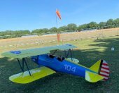
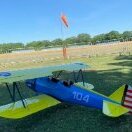
Today was the day, the weather was warm and sunny with an increasing Easterly wind throughout the morning, which is a cross wind for our strip. After the normal safety checks being carried out, a quick taxi around showed there was not enough rudder/tailwheel movement, so the range was increased from 20mm each way to 40mm each way. The aircraft took off with out any adverse yaw (so 2.5 degrees RH thrust was about correct) 3/4 throttle was enough to get it airborne, once at altitude I let go of the controls and no trim was required. After cruising around, I tried a roll, and it was the slowest roll have ever done!!! Landing was a breeze, just glided in with a touch of power before landing. Aileron range was increased to 11mm up - 9mm down, the lipo was changed from a 4S 3300 to a 4S 3700, the second flight again was fairly uneventful, but the wind was picking up and I seemed to be flying at high power more, the roll rate improved. The 3rd flight had a 5S 3500 fitted and felt more 'comfortable' with the power, but the cross winds seemed to blow the aircraft around which started to get a bit of a handful above the tree line. After a discussion with the elders of the club it would appear aileron differential is not required as this model has a slight dihedral. So back to the workshop to fit the cowling.
-
All finished other than the maiden and the final fit of the cowl. Just waiting for a calm day. It balanced at 85mm with a 4S 3300mah Lipo, there is room for 4S 5000mah and 5S 3500mah if needed. Currently I've got 2kg of static thrust with a 12x6e, so that should cruise around quite nicely. Pictures at the field to follow. Ranges set at - elevator 22mm up and down, Rudder 25mm L&R, Aileron 9mm up, 7mm down. The weight came in at 3.1Kg AUW (quoted on the box lid was 2kg but not sure that included the engine and wouldn't of included the fuel) so 400g over I reckon.
