


Paul Williams
-
Posts
467 -
Joined
-
Last visited
Never
Content Type
Profiles
Forums
Blogs
Gallery
Calendar
Downloads
Posts posted by Paul Williams
-
-
Our club committee has decided to update the club rules and we had a meeting to discuss the matter last week. One proposal is a blanket ban on models in the category of 7kg-20kg unless the operator has a B licence.
I disagree with this my opinion is the risk of having an accident flying this type of craft is less than flying smaller planes. I base this on the fact that the planes are much more expensive so the pilots are less complacent, the regulations governing them are more stringent regards fail safes and servos ect. The planes are easier to see so the pilots less likely to become disorientated and personally I give a great deal more respect to a 22” prop then small ic engines.
The other issue I have is with the B test being suitable. The test is principally the same as an A where safety and pit control is the subject, only the flying schedule is different and far more aerobatic than the planes would be expected to perform. I would not consider doing a three turn flat spin exiting in the same direction with my corsair.
You could do a lot of serious damage with a 60-120 IC model the type we witness hitting the deck on a regular basis why pick on some thing with a good safety record?
I would like to canvass other peoples opinions on this matter maybe I am bias because I love to fly these models and feel aggrieved that I now have to do a test to do so.
-
Thanks for the feedback guys its fitted to firewall .
-
Thanks guys I think I will go for it there is enough room to fit a heat sheild so should be ok.Great pics very professional job.
-
Hi allI am fitting a RCGF engine into a large scale P47. I am wondering if the ing unit will be ok fitted inside the cowel. I know this is not an ideal enviroment but there are numerous problems if I fit it behind the fiewall. It would be sited at least 2" from the exhaust. What are your thoughts please as anybody done this without problems.
-
The firewall is lamented with ¼ and 1/8 ply to make up 3/8 they kindly centre punch the centre thrust line for you so mark out engine hole centres from this datum point and fit the captive nuts. I like to dill 2mm hole so they don’t stress the wood to much when you pull them in.Before gluing in the firewall, drill and screw through the sides this holds the wall in place as the epoxy is setting and gives the joint good strength
Before final fitting I will fit the tank and look at throttle links, The tank is massive 32oz it should fly for hours with a petrol engine, the good news here is they supply a petrol bung and tygon tube as well as glow stuff. Nice touch that. Tank as been pressured tested in the sink and that’s enough for today.
One of those days when you spend more time thinking than doing, I test fitted the engine and was quite surprised at the distance I needed to make up to bring the prop driver to the right position.

At nearly 40mm short it meant the stand offs would have to be 85mm long. I did not fancy that I wanted some solution more robust. I ended up laminating some oak off an old headboard to extend the firewall I have a feeling using the lighter RCGF engine I will need weight up front anyway.

> -
My first niggle today the control rods would not run smoothly, the holes for the support tubes are pre-drilled in the formers I had to pull a line tight mark off and re-drill the tube support holes. All is well now and no binding is evident. Not much to write up as it was a nice afternoon I spent time with my Warhawk. Still trying to source some 5” wheels for this any ideas?
Every now and again in this cheap through away society I get impressed with the quality of certain items, I purchased a duel switch and charging point off ebay it came in two days have a look
All steel no cheap plastic here, brill
Ok push on a bit, the control horns are a bit tricky you have to dig out the soft balsa and epoxy in hard wood sections to mount the horns onto. Mmmmm I’m sure they could come up with a better idea. Still job done.
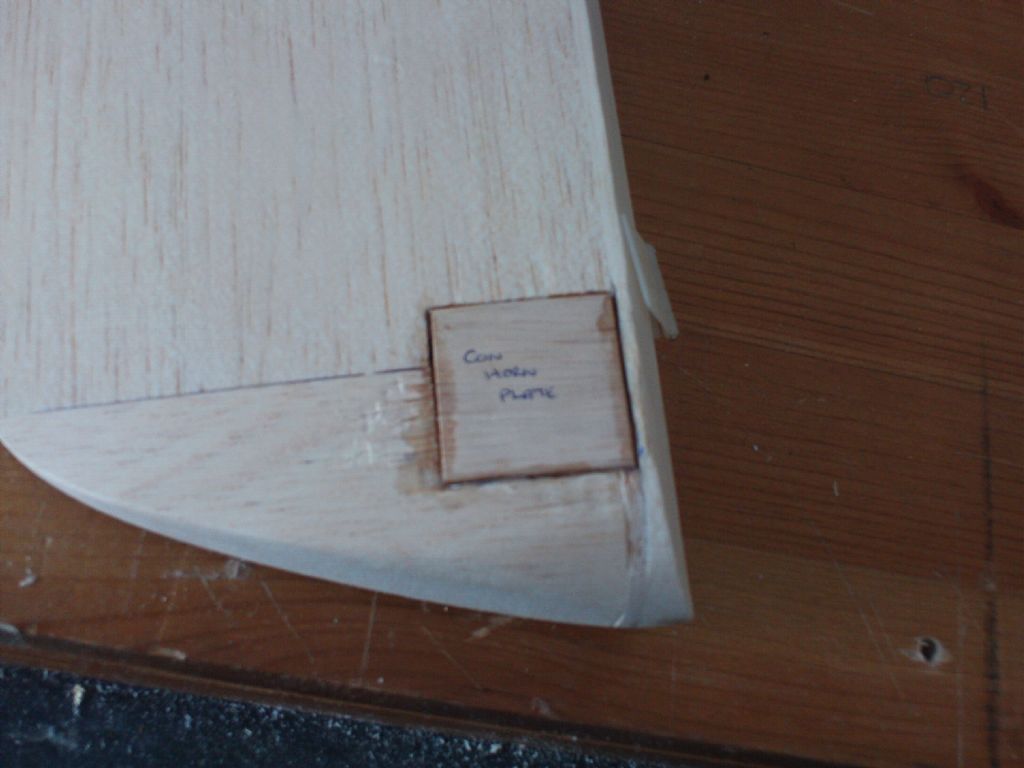
Then I offered it up to mark the horn position RATS I had only fitted it to the wrong side of the rudder. When ever I do anything stupid like this my old fella’s words come to mind “you ain’t made a mistake lad till its on the six o clock news”
Making sure this time the two elevator half’s are done.

Epoxy the control tubes at both ends and cut flush


Drop in some 12kg torque servos from our friends at Giant Cod and solder the cleeks on the push rods, extending the rudder rod with a soldered coupler.
 Now the rods are in place I can look towards the front end.
Edited By Paul Williams on 23/01/20
-
Thanks top shop
-
Any ideas where I can get 5 inch scale P40 wheelsThanks
-
In November of that year the company signed a contract for two prototypes (the XP-47 and the XP-47 A) to be powered by liquid-cooled Allison engines.
The choice of this powerplant turned out to be a mistake, however. Early combat experience from Europe had made it clear that fighters had to be heavily armed and armoured, as well as offering higher performance. The Allison engine was not powerful enough, nor could it provide satisfactory performance at high altitude.Kartveli therefore developed an alternative project around the most powerful engine then available, the new 2,000 hp Pratt & Whitney Double Wasp radial. He literally designed his aircraft around this large engine and its complex exhaust-gaspowered supercharger, submitting the scheme to the USAAC in June 1940. This time the project, the XP-47B, was accepted without reservations.
A first order for 773 aircraft, worth $56.5 million, was placed while the design was still on the drawing board. Of these, 170 were built as P-47Bs, 602 as P-47Cs and one as the pressurised XP-47E.The prototype, the XP-47B, took to the air on May 6, 1941, after final adjustments to the engine and supercharger. During flight tests the Thunderbolt showed what it could do, reaching speeds over 410 mph and climbing to 15,000ft within five minutes.
It achieved these results at a take-off weight of almost five and a half tons.
In March 1942 the first production models started coming off the assembly line, and in April 1943 the 56th Fighter Group, attached to the 8th Air Force in Britain, was the first to take the new fighter into combat over Europe.The P-47 Razorbacks Thunderbolts were successful escorting B=17 and B=24 bombers.
Edited By Paul Williams on 16/01/2011 21:28:24
-
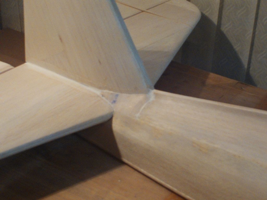
The last step is to fill the gaps between stab fin and fuse with carefully shaped balsa sheet, you will notice the rubberised filler which takes up the small gap. This is an important step taken to allow the tail section to flex whilst the powerful 65cc engine pulls the plane upwards vertically. Ok I’m telling porkies I left my glasses at work!
 <
<
Clear the board and on with the fuse bottom section but before we do here are some stats on this plane.Republic P-47 Razorback Thunderbolt
Type: US escort fighter and fighter-bomber.
History: The Republic P-47 Razorback Thunderbolt was an outstanding fighter, both in the bomber escort and ground-attack roles. It was the largest and heaviest single-engined fighter built during WW2. It was the last in a series of aircraft that began in 1936 with the Seversky P-35 and included the P-43 Lancer in 1940.
Common to all these aircraft was their designer, Alexander Kartveli. In the Republic P-47 Thunderbolt he produced an aircraft that brought the formula to fruition and made up for less successful earlier attempts.
A total of 15,634 Thunderbolts were built in several versions. The 'Razorback, as the first models were called by pilots and ground personnel, was employed intensively by the USAAF and RAF.
After initiating the unlucky P-43 Lancer project, chief Republic designer Kartveli began work in 1939 on two other fighters derived from the Lancer. These were the AP-4 and AP10. The AP-4 was derived from the P-35 and was powered by a radial engine, while the AP-10 was designed as a light fighter around the liquidcooled Allison V-12 engine.paradoxically, the massive P-47 Razorback was derived from the lightweight AP-10. For a single-seater the P-47 was a huge aircraft, weighing almost nine tons at take-off. Indeed, when Kartveli submitted the AP-10 design to the USAAC on August 1, 1939, it was rejected and he was asked to develop a larger and more powerful version.
-
-
I got fed up with balsa so to pass some time I went to play with the new engine.Here we go, will it live
-
I was not happy with the fin support it’s a butt joint onto the TE of stab I reinforce such joints with cocktail sticks simply drill 2mm hole and standard sticks are a nice tight fit a drop of cyano helps.
Cut off and sand smooth. -
Before I carry on I have skipped forward a bit in the instructions and it is evident I will be needing the tail wheel stuff shortly. I phoned Steve Webs and asked for a quote. The main gear £340 and the tail wheel £156 I fell over! No way am I paying that so out with the laptop and start surfing. I ended up on Robart’s site and the prices where much better £199 main gear £99 for retracting tail wheel. Its still hideous but better. I spoke to Webs and asked why I can get them cheaper they reckon its because they purchase through Ripmax or is that Ripoff ! I am tempted to buy a Miller and Lathe but the Mrs went for the rolling pin when I suggested they would fit in the conservatory ha ha. It’s a pain to purchase from America but that’s the way I have gone. The good news is Robard supply a detailed drawing to download so if they have not arrived I can make a template and carry on.I fitted the Stab onto its saddles this morning, I would have preferred to check the incidence before gluing but there is no ref to the angle either on plan or in the book. I should have an incidence gauge its on my shopping list however I have gambled on the incidence being 0 this being the case a few pins on the centre lines both TE and LE then measure to building board. As it worked out there was less than 1mm difference in the measurement so hopefully 0 deg is where it should be,
This subject of incidence and washout baffled me for ages until I test flew some guys bi-plane he had built. The plane flew awful and I helped sort it for him, the problem was incidence. Have a look at this http://www.robart.com/sites/default/files/How_To_Meter.pdfRight stab fitted on with the fin, and once again our profile template comes into play
 Best thing I ever bought lol
-
Once completed we can start the sheeting, This is the first model I have built that will be 100% sheeted, So I am nervous at this stage and plan to take my time please bear with me. The first taxing piece I came to was having to shape the sheet around the LE of the stab.

After numerous attempts to make a card template I gave up and went for a walk round B&Q for inspiration and presto in the tiling section I found a shaping template tool. Its got to be worth a tenner if it saves the frustration.
Simply push it over the profile then transfer to sheet

Not bad happy days

-
thanks for the tip Richard I did try all directions, I am convinced its the wood maybe its from the centre of the tree or some thing daft, anyway onwards.Ok clear of the board and on with more taxing aspects. It was not untill I laid out the main stringers I started to get an idea just how big this was going to be. I placed a six inch rule on the plan here to help you see.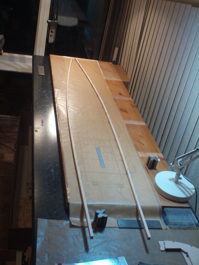
The stringers are quite beefy so to help make the curves they mill a 1/4 slot part way through and you fill this with balsa strip after its pinned. Simples
add a few formers, tank support and cockpit deck and very quickly it starts to take shapeAt this stage you need to make your mind up as to bubble canopy or razor back version

I love the look of the razor back and for the extra work involved its my choice so order canopy and press on.
Being careful to add the correct formers butt join and add stringers

> -
However thinning down the tips was another story, I tried a razor plane but it just ripped and refused to cut the balsa. It was like cutting cross grain.
In the end I just used a sanding block and swore a lot. I will take advice gratefully.
The fin and rudder are more of the same

> -
So say hi to Bradley who will not be allowed into the conservatory because he loves balsa wood. On with it then.
To be honest when I opened the box I thought christ what have I done, I spent the first morning going through all the die cut parts and marking them up It may seem a waste of time but it really helped me get a mental picture of what goes where.
The first section to build was the stab

I have to say I love the method Topflite employ having tabs on the under side of the ribs, It saves having to protect the plan from glue damage as the build is done over the plan rarther than on it.
After the top side is complete and sheeted they supply die cut jigs to lay the stab on whilst the other side is sheeted. The balsa blocks supplied for the tips are already cut to the correct radius

-
-
I thought long and hard about the power plant Topflite recommend 40cc-70cc petrol or same power glow, I really fancied a radial but the budget would not stretch that far so a 65cc RCGK from Al's hobbies was ordered.
The 50cc RCGK used in my Corsair has proved reliable to date so at £170 its worth a risk I purchased a Pitts muffler for a further £50 and all arrived in two days. The spec is;
Bore: 48mm
Capacity: 65cc
Carburettor: Walbro
Engine Type: 2-Stroke Petrol Engine
Max. HP: 5.5hp/4.1KW
Propeller Range: 22x10, 21x10, 22x12 (2 blade)
RPM Range: 1500-8200 RPM
Stroke: 36mm
Weight: 1835g/2097g (Exc/Inc Ignition + Muffler) -
First of all a very happy new year to all.I am normally well on with the winter build buy this time but her indoors demanded the conservatory for xmas parties and I could not face to pack up once started, the garage is far to cold for my old bones so the instruction book for this kit has been read numerous times before the balsa was touched.
Here is what it should look like when finished This is the bubble canopy version I intend to build the razor back more on thatlater.
 -
Thanks guys will sleep tonight now

-
Can any wiz help please, I have changed my electric set up on my 1/4 scale cub. Instead of NIMH I have installed a Li-Po and Ubec system. I am concerned that the Ubec is capable handling the current. Its rated 5amps with 7amp burst. The trouble is how do I access how much current the servos are pulling under load,
-
AND THE WINNER IS--------------------------------------PlasticardThe drinks bottle thing is to small thanks guys I should have mentioned its 1/4 scale.I was impressed with the plasticard its cheap and comes in all thickness and sizes plus you can use a product called milliput an epoxy based putty various colours to putty in the windows, fantasticYou never stop learning.


Which glue
in Hints and Tips
Posted