Martyn Johnston Posted August 8, 2011 Author Share Posted August 8, 2011 A second-hand one;- but just look at all the hundreds of hours hard work you're missing out on !!!!! Quote Link to comment Share on other sites More sharing options...
Martyn Johnston Posted August 8, 2011 Author Share Posted August 8, 2011 What size is it? Is it the 3.4m one like mine? or I think there's a smaller 2.5m one around too. Where you based? I'd love to see it flying. Quote Link to comment Share on other sites More sharing options...
Tim Mackey Posted August 8, 2011 Share Posted August 8, 2011 I think he said it was 2.5mtr - but I dont know what make it is.Heres a picture of the actual model. I'm in North Wales Martyn. Quote Link to comment Share on other sites More sharing options...
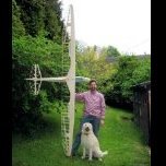
Tim Mackey Posted August 8, 2011 Share Posted August 8, 2011 May indicate the size better - here she is with the seller Quote Link to comment Share on other sites More sharing options...
Tim Mackey Posted August 8, 2011 Share Posted August 8, 2011 I have now been given a little more info on my soon to be acquired babyEach wing panel is approx 66 inches long with a chord of approx 12 inches. The Fuz is approx 58 inches long.It is of a traditional build . i.e balsa, ply & covering is solartex.I believe it was built from a plan ( Mike Trew was the model designer) I was told .So, that seems to be around 11.5 - 12' wingspan allowing approx 6 -12" for fuselage width.That makes it more likley to be closer to yours at approx 3.5Mtr then I'll have a google around to see if I can find any more info on the plan - but at least we know now its not the krick kit.Sorry to have hijacked your thread Quote Link to comment Share on other sites More sharing options...
Martyn Johnston Posted August 9, 2011 Author Share Posted August 9, 2011 Lovely photos, but how can it possibly fly; - it doesn't seem to have a pilot.Edited By Martyn Johnston on 09/08/2011 09:28:21 Quote Link to comment Share on other sites More sharing options...
Tim Mackey Posted August 9, 2011 Share Posted August 9, 2011 No worries, it will have a bod installed as soon as I get me hands on it Quote Link to comment Share on other sites More sharing options...
Martyn Johnston Posted August 16, 2011 Author Share Posted August 16, 2011 Doing well with the cockpit, but did make a bit of a booboo. I put masking taoe around the edge of the fuselage first, as instructed. I then used this opportunity to spray-paint all of the inside of the front-fuselage with grey primer (just 'cos it looks nicer). I then tack-glued the floor of the cockpit on to this tape, and built the rest of the cockpit onto that floor. Once I had it all finished it's supposed to be easy to just cut it free, but it was a right job. I'd added some thin CA to help hold to side panels to the curved floor, and it must have seeped through to the fuse itself. Glued it solid it did. Anyway all OK now, I managed to carve it out without too much damage. Need to cut the curved cockpit opening out, and the plan isn't at all clear here, but I'm sure I'll manage. Then I'll take a photo.Edited By Tim Mackey - Administrator on 16/08/2011 13:26:28 Quote Link to comment Share on other sites More sharing options...
Martyn Johnston Posted August 24, 2011 Author Share Posted August 24, 2011 Cockpit coming on lovely, but the instructions are (typically) vague about details. There's no real clue as to where the cut-out should reach to for the canopy, and, similarly, no detail as to where, or how, to fit the two little round windows. So I've guessed. I intend to put a fair bit of cockpit instrument detail, so I might need to move the cutout forward a bit, later. The cockpit is very shallow though, doesn't seem to be enough room to fit a pilot (maybe a head only !). Quote Link to comment Share on other sites More sharing options...
Tim Mackey Posted August 24, 2011 Share Posted August 24, 2011 I have started a bit of fettling on mine now - kicking off with a darn good if rather harsh cleaning with cellulose thinners the fuselage. I applied a few non scale stickers and reg letters to hide a couple of tears in the solartex, and must say, I think its looking rather tasty.Ill put a couple of pics up if you dont mind Martyn, but then Ill leave your thread alone Quote Link to comment Share on other sites More sharing options...
Martyn Johnston Posted August 24, 2011 Author Share Posted August 24, 2011 Please carry on Tim, if it was just me posting I'd get bored and stop. And people always want to see other ways of doing things. I see yours is white; I've not got as far as thinking about colour schemes yet. Have you any idea about a pilot? I want a good, realistic one, but there's very little space to fit one in the rather shallow removable cockpit.Edited By Martyn Johnston on 24/08/2011 10:27:00 Quote Link to comment Share on other sites More sharing options...
Martyn Johnston Posted August 24, 2011 Author Share Posted August 24, 2011 I've trial fitted the hinges for the empennage this weekend. I've bought some of the Robart pin hinges, rather than the supplied little plastic hinges which need slotting in. No particular reason though. I've had to add some small bits of balsa as extra supports for these hinges though, as they're quite long. Fuselage looks 'huge' now. Quote Link to comment Share on other sites More sharing options...
Martyn Johnston Posted August 24, 2011 Author Share Posted August 24, 2011 Now having major difficulties getting my head around the elevator servo. I decided earlier not to fit the elevator push-rod and its funny linkage thing, as described in the instructions because, as my wife is always reminding me 'I know best'! I've fitted a low-profile servo within the stabiliser itself and fitted a short push-rod to the elevator horn. It was only then that I realised that there is a horizontal hard-wood support for the rear captive-nut fitted in the fuselage, flush with the top of the fuselage, and right slap bang in the way of my push-rod. Quote Link to comment Share on other sites More sharing options...
Martyn Johnston Posted August 24, 2011 Author Share Posted August 24, 2011 I'll now have to find a way of rerouting this push-rod so it fits over the top of this wooden support (it naturally wants to go underneath it, but that would be impossible to fit. (remember these two photos are of the tailplane upside-down). The markings on the masking tape in the photo are where this wooden support sits, and it is flush with the base of the tailplane, so there is no gap between them for the push-rod to fit. Somehow I'm going to have to cut a slot in the tailplane wood and bend the push-rod to slide in it.Edited By Martyn Johnston on 24/08/2011 10:39:54 Quote Link to comment Share on other sites More sharing options...
Tim Mackey Posted August 24, 2011 Share Posted August 24, 2011 Thanks Martyn. I have a few used pilots here, and also a new latex WW1 type chappy, who I may just modify a little. I have also ordered a cheapy "glider" pilot from Hobby King.Your right, theres not much room for anything more than a head though Funnily enough, I was wondering about modding the tail end to fit rudder and elevator servos in the fin / fus, and then I could remove the whole back section to make it easier to fit in the car - a la what did for my PC9. Obviously it would be more difficult with the baby, due to its construction, and already being built etc, so Im still pondering that one. Also, this seems to have a large lump of lead in the nose already, and the el and rudder servos are well up towards the front, so balance could be become an issue. Maybe Ill just stop trying to give myself more work and leave well alone Pictures a bit later, my bech is full of other stuff right now. Quote Link to comment Share on other sites More sharing options...
Tim Mackey Posted August 24, 2011 Share Posted August 24, 2011 I'm beginning to wonder if this is the same model you know - the vertical stab and rudder construction look the same, as does the fuselage generally? Did your front end small round windows come ready cut - mine has none. Wings are 66" each panel, so seems like the same span?The air-brakes are driven off a rather messy arrangement involving plastic snakes with ball ends, that are pushed onto servo ball joints, in the wing pod housing. The servo arm has to be removed each time - I may see if I can fit small servos in the wings instead.All Ive done so far is give the fus a really good cleaning, and covered one or two small rips in the solartex with some reg numbers and non scale stickers Ive removed the tailplane ( screwed rods and nuts, and struts ) for examination, and discovered that one of the screw holding plates is loose - so have just glued some 1/4 sq balsa strips to re-secure it. Otherwise, all looks good so far - the model appears to be well made, with strong, accurate and neat woodworking, hinges are secure, pushrods and metal rod ends etc seem strong and well bound. Elevator has pushrod, rudder is closed loop via idler crank.Ive changed the slightly rusty clevis'. S148s waggle rudder elevator, and air-brake, but the elevator servo top housing/bushing is worn, so that will be replaced.1.7 lbs of lead was rattling around the nose - so may try to reduce this dead weight by using A123 cells for power, and a nose release system needs fitting too, as I plan on aero-towing her. More on this later. Found an unused WW1 pilot in the bits box, so may try to adapt him to fit /look right.Scrubbed up pretty well me thinks 1.6 lbs of finest church roof airbrake servo elevator clevis access first look inside rear end Edited By Tim Mackey on 24/08/2011 19:05:36 Quote Link to comment Share on other sites More sharing options...
Tim Mackey Posted August 24, 2011 Share Posted August 24, 2011 Here's the tailplane seating area under repair. And also a couple of pictures - as best I could - of what appears to be part of a tow release mechanism right up in the nose. A plastic pivot tube runs across the nose block, with a rod through it, to which is attached a plastic and brass thingy ? Being new to aero-towing, I cant quite see how it operates, but the chap I bought it off is sending me some more bits, so maybe then it will make sense. Quote Link to comment Share on other sites More sharing options...
Tim Mackey Posted August 24, 2011 Share Posted August 24, 2011 Few more piccies... Quote Link to comment Share on other sites More sharing options...
Martyn Johnston Posted August 25, 2011 Author Share Posted August 25, 2011 Looks like a 'Grunau Baby' to me, - but it's not the same 'Krick' kit. Mine will be 1:4 scale; 3.4m (134") in total. The wing seat is definitely different. My two wings will mate together, and then this assembly will sit 'on top' of the the fuselage. Tail and fuselage look very similar though. I like the foam blocks you have; I'll copy that idea if you don't mind. The round windows were supplied, but it would have been easier not to cut the holes out. I think all the real Grunau Babies had holes though. Your pilot looks rather small; what scale is he? I've been looking for a 1:4 scale bloke, and I'm only going to be able to fit just a head in ! Can't make out your tow-release though; I've bought a very simple looking Multiplex one (link here); I've glued it in but won't get round to setting it up for a while yet. My plan suggests something similar for the ailerons and the airbrakes; but I'll be using seperate small servos in the wings instead. I like the look of your closed-loop rudder idler crank thing. I've done something similar before but it ended up being very oversized and heavy. Quote Link to comment Share on other sites More sharing options...
Martyn Johnston Posted August 25, 2011 Author Share Posted August 25, 2011 Good info on the early versions of the Grunau Baby here. Not all versions had the little round windows. Quote Link to comment Share on other sites More sharing options...
Tim Mackey Posted August 25, 2011 Share Posted August 25, 2011 Ok, it probably isn't the same ( although the span is identical I think, with 66" panels, and 2 " fuselage width ) - in fact, I am thinking that this may well be a scratch build from plan, as the more I dig - the more "home made looking" pieces I find. All the horns, pushrods, struts and mountings, cross bracing where the struts attach etc, all seem home brewed - but very well done I add.I have decided to strip out all the gear as the servos are all showing a bit of slop in the top "bearing" and the geometry of the elevator system means the resultant torque is marginal at best, from a simple old S148. The plastic servo tray is also flexing a fair bit under load, so I'm redesigning this and making a plywood radio tray that will house 3 servos ( elevator, rudder, and tow release ) along with Rx and switch and charge jack.Im going to re-use the best of the existing servos for tow release where a little play wont matter too much, and fit higher torque, new, HiTec servos on rudder + elevator. Mini servos will be fitted in the wings somehow for airbrakes - when I finally get around to the wing work. All wiring will be concealed, and battery pack made to fit right in the nose. I thought about the foam "stand" as its a nightmare to try and get it sitting on the bench due the skid. Now, on that subject, as I say...Im new to aerotow, and Im wondering how the thing is going to fare when being draggged along, balanced on a half inch wide strip of hardwood. Whats stopping the wingtips from catching the grass, and maybe even digging in on take off or landing? I've heard talk of using a dolly, but would really like to avoid that if possible. Quote Link to comment Share on other sites More sharing options...
Tim Mackey Posted August 25, 2011 Share Posted August 25, 2011 Posted by Martyn Johnston on 25/08/2011 15:49:21:Good info on the early versions of the Grunau Baby here. Not all versions had the little round windows. Yup, found that link a few days back - I think mine maybe a 2a. That looks a nice simple ( simple is best on something like this ) tow release Not sure what scale the pilot is, certainly nowhere near 1/4 scale, but oddly enough, his head and shoulders dont look too wrong in the cockpit. Edited By Tim Mackey on 25/08/2011 23:37:31 Quote Link to comment Share on other sites More sharing options...
Fubar Posted August 27, 2011 Share Posted August 27, 2011 Gosh Tim she does look clean. That plastic servo tray needed to be removed Quote Link to comment Share on other sites More sharing options...
Tim Mackey Posted August 27, 2011 Share Posted August 27, 2011 Yes, scrubbed up really well Chris - wanna buy her back ? Quote Link to comment Share on other sites More sharing options...
Tim Mackey Posted September 30, 2011 Share Posted September 30, 2011 OK, she's pretty well finished ( hows yours coming along Martyn ?). First off I made a large 1" diameter, 7" long aluminium tow release that fits right up tight against the inside of the nose, but the hooking mechanism is visible inside the cockpit area. I prefer this as it allows me to actually see the towline is properly "hooked". I forgot to take pictures of its construction, but its a solid 1" round bar, conical at the front, bored out right through with a slot at the rear, through which a hooking lever is swivel pinned and servo operated.The hook/lever was simply filed down from a piece of 1/8" flat bar, and the pivot is a cut down old drill shank, hammered home and peened over slightly. This is the business end just inside the cockpit area and the operating servo is under the new rear ply false floor. The new radio bay. I did away with the idler crank for rudder, as it was binding a little and the rudder would not always centre correctly. New longer closed loop lines now run directly to the new rudder servo. Elevator is pushrod driven using original rod and fittings. The front tray also houses the on/off switch - radio power is from 2 x A123 2300 mahr cells in the nose - along with much reduced lead ballast. The charge/balance socket for the battery can just be seen behind the elevator servo. Rear false floor. This hides all the wiring and tow release servo, and just visible is the wing wiring harness running up along the former, and the spektrum Ar7000 master receiver, with the satellite on the floor to the rear. Much tidier install now - and no flexing under load I made a "padded headrest" from an old mousemat for the soon to be installed 1/5 scale pilot He's slightly smaller than true scale, but at 77mm height and with real woolen clothes and fetching nylon hair, not bad for 14 Euros. Pity the postage cost 15 !!....."Max" is on his way from France, having now become too old for leading roles in those dodgy 80s "movies" I didnt fancy fiddling with little 3mm nuts and bolts for the wing struts, so made up some locking pins on the lathe - the struts will remain bolted to the panels, but these new fuselage fittings are retained by a small "R" clip, itself retained by a safety line to avoid losing them in the grass.Heres the pins and clips in more detail. Im not happy with the wing seating, as can be seen below - theres a very noticeable gap at the front of the right hand panel. The wings slide onto two metal joiners, and are held together with "O" rings across two hooks, front and rear. Even smaller stronger rings are not pulling hard enough for a good fit - so I am still deliberating a method to exert more force. I have ordered some small "bottle screws" like turnbuckles, but mnay need to fix new hooks to the wing root to allow room to operate them - I could just use tie wraps, but would prefer something better. Edited By Tim Mackey on 30/09/2011 1 Quote Link to comment Share on other sites More sharing options...

Recommended Posts
Join the conversation
You can post now and register later. If you have an account, sign in now to post with your account.
Note: Your post will require moderator approval before it will be visible.