


J.N.
-
Posts
122 -
Joined
-
Last visited
Never
Content Type
Profiles
Forums
Blogs
Gallery
Calendar
Downloads
Posts posted by J.N.
-
-
Posted by RAF-P on 16/01/2012 11:44:55:
Hi Seamus, JH,I hope my comments about the problems I have had with my Storch as not put you off because when she is flying OK she looks just great in the air and is fun to fly."I am not quite sure what the problem with the wing connections is. Is it where the 2 graphite Wing Connections slide into the 4 wing connector holders, item 88 and 89( shown in Fig 21on the plan) and are held in place by grub screws. If so it would appear that the whole wing retention to fuselage needs beefing up. If you could manage to post a photo it will be much clearer what the problem is. "JH, your ref above to the wing problem I have had is correct. I don't think it needs any beefing up just another way of holding the wings tight to the fus at the fus centre section/wing root. At the moment when things go wrong and she has a coming together with the hard ground everything moves and gives a little without to much damage. All my repairs to press have only been to the fus to wing strut attachment points and the U/C. So I am thinking of only putting two 3mm nylon bolts somewhere at the wing root rib and fus centre section so that they will give before any damage to the wing etc.PeterEdited By RAF-P on 16/01/2012 11:45:30
I am not an expert however I do not think the wing securing grub screws are load bearing, I suspect they are just to hold the wing in position until the wing struts are fitted. Maybe the wing flexes and pulls away from the graphite wing connectors because the fuselage and wing mountings for the wing struts are not up to the job. The fault could lie with the wing struts and not the grub screws. If all the wing strut mountings were reinforced, and solid fixings to wing and fuselage were used, then surely the wing would be prevented from moving, bolts fitted through the wing connectors would then only have to cope with any pulling movement. Or, the wing connectors themselves are not strong enough. -
Posted by RAF-P on 14/01/2012 14:28:24:I have added a couple more photos, they show the A/C U/C that I used to mod my Storch.I also have a 3D drawing that I found on the net which I used to get the correct angles etc.You may be able to find it by searching FIESELER 156C-3 STORCH . It was drawn by: KARLSTRUM.The main problem I found with the kit U/C was the grub screw holding item 102 in item103. If and when it slackens off it allows 102 to turn!! Or in other words when this happens on landing/takeoff the main wheel turns 90 degrees!!!!!My modified U/C....... The main leg is now one piece, ie 1 port and 1 stdb.I still use items 106, 108, 112, 113, and 103.I made 2 new 109 to fit and you only use 1 grub screw in 106 and no!!! grub screw in 103.This allows full movement to the main U/C leg.The 2 new main legs still slide into the brass tube item 38 on the fus drawing.All the new U/C angles I worked out using the 3D drawing.Now my plan of action for the wing, I am thinking of using 2 nylon screws and anchor nuts each side at the wing root rib and centre section ribs. This I hope will then do away with the 2 grub screws. This will not be easy on the finished A/C, also how to tighten them is not going to be easy!!!PeterAfter claiming the underacarriage has been resolved it I dawned on me this morning that I still have not preventing the wheel with its axle (102) moving within the L/G Lower Support (103) taking with it the brass tube (101) if the grub screw cannot be relied on to keep everything square. The Wheel Axle (102) has to be securely fixed in 103, as you know 103 is aluminium making it difficult to select a suitable fixing medium. I am tempted to make a new 103 out of steel and hard solder 102 in place whilst keeping the heat away from the brass tube (101).I sympathies with you and Seamus, remedies are coming to light that could have been sorted out at the building stage.
-
Posted by ColdTurkeY_UK on 13/01/2012 21:44:42:
Well J.N. You have been of great help to me and I thank you kindly for the help, guidance and particularly the photos of your aircraft. I only hope my build goes smoothly and I hope should I need some guidance you wouldn't mind answering questions for me.Glad to be of help, what goes around comes around.If you think I can be of anymore assistance, just ask.Regards. -
Posted by RAF-P on 14/01/2012 14:28:24:I have added a couple more photos, they show the A/C U/C that I used to mod my Storch.I also have a 3D drawing that I found on the net which I used to get the correct angles etc.You may be able to find it by searching FIESELER 156C-3 STORCH . It was drawn by: KARLSTRUM.The main problem I found with the kit U/C was the grub screw holding item 102 in item103. If and when it slackens off it allows 102 to turn!! Or in other words when this happens on landing/takeoff the main wheel turns 90 degrees!!!!!My modified U/C....... The main leg is now one piece, ie 1 port and 1 stdb.I still use items 106, 108, 112, 113, and 103.I made 2 new 109 to fit and you only use 1 grub screw in 106 and no!!! grub screw in 103.This allows full movement to the main U/C leg.The 2 new main legs still slide into the brass tube item 38 on the fus drawing.All the new U/C angles I worked out using the 3D drawing.Now my plan of action for the wing, I am thinking of using 2 nylon screws and anchor nuts each side at the wing root rib and centre section ribs. This I hope will then do away with the 2 grub screws. This will not be easy on the finished A/C, also how to tighten them is not going to be easy!!!PeterThanks.I am sure Seamus will read this as well, greetings.
First. I think the quality of your finish is great.I would very much prefer your colour scheme but I am a little concerned that through lack of attention I may allow my Storch to fly too far away and become confused which way is up. It wo`nt be the first time, however that is some way off yet and I will have to become more disciplined in my flying.
I appear to have got my undercarriage right although I wish I had soldered the wheel axle securly into the brass tubing, I will look again at the wheel axle and see what can be done.I am not quite sure what the problem with the wing connections is. Is it where the 2 graphite Wing Connections slide into the 4 wing connector holders, item 88 and 89( shown in Fig 21on the plan) and are held in place by grub screws. If so it would appear that the whole wing retention to fuselage needs beefing up. If you could manage to post a photo it will be much clearer what the problem is.There is me thinking that a size 70 Laser is too big, I am going to order an 80 Laser.
-
Posted by RAF-P on 12/01/2012 20:08:00:I have an ASP 65 fs fitted, more than enough power.PeterPerhaps you and Seamus are prepared to comment on my engine choice which is about to be placed on order, I have a few days in which to change/cancel.I intended to fit a Laser 70 fourstroke to my Storch. The building instructions recommend a size 60 four stroke and 12x6 prop although on the outside of the box it states that suitable fourstroke engines are size 60-90. Laser recommend a 12x8 for their 70 engine.I have no idea how your ASP 65 and ASP60 compare to a Laser 70, I am now concerned that a Laser 70 may be to powerful in light of your comments on your present engines.I have to catch up on your emails, in the meantime I endorse the thanks to Seamus for starting this thread.
-
Posted by Seamus O'Leprosy on 13/01/2012 20:46:31:
Yep mine are held with those small screws, absolutely rubbish
may have to come up with a mod also. Pitty I didn't know when I was building it things would have been easier.Will you please let me know what the problem is. I can still access these mountings and have the opportunity to make modifications if I knew what had to be modified. -
Posted by ColdTurkeY_UK on 11/01/2012 22:38:28:
That's just the sort of post i was hoping for J.N., thank you very much for your advice and I will certainly be using that information in my build,I am not an expert by any stretch of the imagination, no matter here is the follow up.I have only one build item to add. Otherwise follow the instructions in the manual and it will be difficult to go wrong. The following are points that may/may not be of interest.1. Page 12 Hatch para 15). Use epoxy to secure rubber band anchors to sides of tank bay. The Anchor is for an elastic band that holds the Hatch down in place and a significant force is needed to pull the hatch up. This strain is taken by the Anchors and they will be pulled off the side walls sooner or later unless securely epoxied in place.A. In my first build I overlooked the note on Page 6, para 9) first paragraph. I built 2 identical fuselage sides and not a mirror image.B.The elevator push rod connection to horn leaves little room for adjusting the elevator end clevis so do not put a locking nut against the clevis.C. I removed the minimum of material from the cowl to make it fit this meant that I had to remove/ refit the OS LA silencer for the cowl to clear the engine. I drilled holes in the cowl to match up with the silencer allen key headed bolts and used a long allen key to un-screw them. Otherwise chop the cowl as you think fit.D. Fitting Du Bro 3.50 T (3 1/2 inch) undercarriage wheels makes for easier rolling when flying from wet grass.E. I found a GS 2.5 inch aluminium prop spinner to be ideal.F. I found that with the LA engines my Kites were happy to leave the ground once speed had built up. Whenever I tried to haul one off the ground in light winds I have been on the edge of a stall.Photo 1Is the steerable tail wheel, I have included it because it took quite a bit of wire bending. The long horozontal arm was cut in half then after forming and shaping joined up with a brass tube sleeve and soldered in place. The nylon tail wheel pivot housing was secured to a ply base which in turn was bolted to the fuselage.Photo 2Is the fuel tank bay and you can see one of the hatch rubber band anchors. The grey item you can see behind the engine fire wall is a square piece of lead secured with through bolts. This Kite needed a lot of nose weight and rather then have it all attached to the engine mounting I had most of the weight as above leaving a smaller amount for final adjustments which is secured to the rear of the engine mounting. The cowl accounts for a surprising amount of weight adjustment.Photo 3Is the battery box for a flat nicad. The battery lies flat and is a snug fit when packed out with rubber insulating material. Simple rails glued to the sides with a sliding cover between rails and battery held in place by a through long bolt into a captive nut. The red snake is servo to throttle secured in place through a balsa block. I found that without the snake mounting to hold everything in place, the throttle travel could not be held to its set limits.Photo 1


-
Posted by RAF-P on 13/01/2012 16:10:35:Just to let you know that I added a few more photos of my Storch in "My Photos" They some of the build, Finnishing, and flying.Before I try and answer J.N. I have a question for Seamus.In an earlier post you mention Dural Wing mounts, I have Carbon, Are they one piece and are the wings attached and then held in place by small screws .Now for JN, Yes it is an Aviomedelli Storch,and as you can in the photos I build it myself.The engine fitted is an ASP 65fs. No mods to the engine bay.Also no lead needed to get the C of G correct, (moved the battery)I remove the slats for flying for better aileron and rudder response.With my new U/C takeoff and landing are now just great, wheels set with about one degree of toe in helps to stop ground loops.Flaps, well with all the problems I have had, test flight, repairs, test flight, repairs. Give up try again some months later etc, I have only tested out the flaps once at a safe height. They work every well, at half flap the will gain a little height, so you have back off a little on the engine, at full flaps she will then nearly stop! So I would say for take off half flap and landing half or full flap once you are happy after trying them out at a safe height. They are fun to use.Hope the above helps.I have removed the radio gear at the moment, I am going to try a new way of securing the wings as I think they can move during flight and or not always attach in the same place each time!!PeterThanks for the update, the photos are very instructive, glad to see you have the built up wing version. My wing mountings are the same as yours and I will be very interested to know if you modify your mountings.What did you cover the fuselage and wings with?After looking closely at the undercarriage I am concerned that mine is not right. I hope the following explanation makes sense.On mine the L/G lower support 103 has a large enough diameter to accept the brass tube L/G tubing 101. I used the grub screw in the L/G lower support to secure the L/G tubing in place and epoxied the Hubs 102 (axle) into the brass L/G tubing. Suspension movement then takes place with the brass L/G tubing moving up the L/G legs 107 against spring pressure.
-
Posted by RAF-P on 12/01/2012 17:09:27:

 The 2 photos I have posted are a test to see if I can post photos!They show before and after I modified the U/C. I had to replace the first one a couple of times and the aircraft would ground loop. The 2nd photo shows my modified U/C which is stronger and also with some built in "toe in" no more ground loops.Fingers crossed more info to followRAF-PLooks good, is this the Aviomedelli Storch and did you build it yourself?
I have beefed up all the undercarriage mounting points including the brass cross tube mounting at fuselage Former 4 with laminates of ply, small hardwood blocks and epoxy resin. The whole undercarriage linkage is secured in place with washers soldered onto the ends of all fittings after final assembly. The wing braces have been modified along the same lines.What size and make of engine have you fitted and what modification have you made to the engine bay?What Flap setting do you apply for take off and landing?Have you fitted the leading edge slats with a larger exit slot than inlet?What are take offs like and do you have to wait for favourable flying conditions?I had problems making the undercarriage fit and still have sprung suspension. I appear to have made everything work by cutting the main 4 front and rear leg supports in half then after assembling the whole undercarriage, sleeve the supports with brass tube and solder everything solid again.
Edited By J.N. on 12/01/2012 20:12:32
-
Posted by Hogster on 10/01/2012 20:03:03:
Its been a while since I played around with solder and fluxes. But solder core with acid fluxes used to be quite rare. The chances are its likely to be resin. I would use some and if the residue is brownish its resin, acid based fluxes, if I remember correctly, left a whitish residue. We used to use acid based fluxes and washed all residue for fear of corrosion. But I did tests and found no noticable corrosion after several years. Cored Fluxes are temperature dependent and provided your joints aren`t over 70 (conservative estimate) degrees for appreciable length of time I wouldn`t worry.Many thanks for your comments.Edited By J.N. on 11/01/2012 09:13:59
-
Posted by Andy Brough on 10/01/2012 22:21:01:
Hi Vic, I did lash out on a Proxxon Band saw and it is superb. It cuts everything from thin steel, 10mm bolts, ply, 60 mm hard sycamore, brass and plastics! It's also light for under bench storage. I know it's dear but worth every penny and the blades are excellent albeit also expensive. However I did sell a Record 350 band saw beforehand as it was rather too large! I don't like scroll saws, band saws are far better. The downside is that it doesn't have a fence so I share the one off the Proxxon table saw, even more expensive, but is the best small saw in the world. if I had to buy another make then Record are probably the best. Both the saws I bought were done so with substantial discount by buying ex demo models at the end of a show......it is a pleasure to use good tools. Do not buy any of the offerings from DIY sheds as they are crap and don't ask how I know! Cheers.Edited By Andy Brough on 10/01/2012 22:22:25
Edited By Andy Brough on 10/01/2012 22:22:46
Thanks, I did notice the lack of fence on the Proxxon and thought that an after market add on was readily available however your comments have fore warned me to look into the matter before parting with any money.Regarding Scroll/Fretsaw, I must admit that it is sometimes a bit fiddly to lock the blade into the arms after feeding it through the hole in the centre of a former but it is something I have got used to. The Axminster one I have is heavy and solid with a substantial iron table and is capable of cutting anything that I would want to cut on a mini bandsaw, however. I have found that with care, I can cut accurately to the line on a bandsaw leaving very little final sanding to do and still have my fingers. Cutting curves and the like is fine on the Fretsaw but on long (ish) straight bits the narrow, thin blade does not help to keep the cutting line square. -
Posted by ColdTurkeY_UK on 09/01/2012 20:23:14:Hi all,I recently purchased the kit form of the Flair Kite Mk4, whereby I was informed by the model shop owner that this was the best kit to buy (that he had available) to learn to build and fly an aircraft.I would appreciate any tips, tricks, build guidance, advice in a general form or from someone who has built this specific model. I am totally new to balsa wood assembly, so ANY help would be gratefully received.Dan.I have built two, they are everything your model shop claims. Used by the Paul Heckles school and powered by Magnum 51 fourstrokes which suit them to the ground.The Kite is solid, predictable and tough. They will take a lot of punishemt and I have found them easy to repair, the last repair was a 2 inch wide 3.5 inch deep, gash in a wing leading edge. Engines used, OS40LA when it got tired out I fitted an OS46LA, both engines adequate however if like me you are not a skilled pilot I would suggest that a size 46 cooking engine is the minimum. My Kites are tail draggers, you will need a big lump of lead up front, best screwed to the beams of the engine bearer. Built as per the instructions plus a battery compartment for a nicad flat battery in the servo bay against bulkhead to fuel bay. Cable run from throttle servo is a bit tight and you need to give it a bit of thought and offer it up before fixing in place. Covered my Kites in Glosstex. I will post more info when I have given it some thought.
Edited By J.N. on 10/01/2012 21:45:56
-
Posted by J.N. on 15/11/2011 21:09:56:Posted by Seamus O'Leprosy on 15/11/2011 20:42:01:
jn have a look at picture 8 in the first post you will see the items either side of the "B" the mounting points on the fus could be better alsoYes I can see it plainly and it is were I expected it to be following your previous reply.Your "the mounting points on the fus could be better also". I presume this is the liteply keel rather than the undercarriage nylon fittings.I am fitting these undercarriage nylon fuselage mountings, as you will know the nylon fittings are a snug fit on the liteply keel secured with through bolts. I thought perhaps to reinforce the keel at the mounting point area with a section of fibreglass bandage and epoxy, then open out the nylon fitting to fit. Have you any comments or advice. -
Posted by PatMc on 26/11/2011 16:16:58:
If you are going to use the motor with the shaft as it is the thrust from the prop will keep the rotor in place. Only function the circlip might have is to prevent the bearing creeping forward but the prop collet Ken mentioned will limit this. If the distance between bearing & collet is enough to cause concern a suitable washer or two could be used.Not sure what you mean by "keep the rotor in place".At present the Rotor (Can?) attached to the output shaft has no mechanical fixing to keep it in close proximity to the Stator. It is only the Magnetic Flux that prevents the Rotor (Can?) from falling on the floor. In addition, at present, their is a gap of 4mm between Rotor and Stator which can be closed up by pressing the Rotor towards the Stator and overcoming the magnetic flux. -
Posted by ken anderson. on 26/11/2011 15:08:31:hello JN...i take it that the shaft has been reversed?(not sure after looking at the link posted by martin)....if you are concerned about the motor comming adrift in the model/air.... you'll find that the prop collet assembly will hold every thing together...... i have a couple like this and have no problems with them....ken anderson ne..1 ... no probs dept.
Edited By ken anderson. on 26/11/2011 15:10:07
The motor was supplied to fit my model, if the shaft was reversed it may be the reason why the circlip is missing. I can make do by using appropriate packing in addition to the prop collet, however I much prefer to fit the appropriate item, when all is said and done it would only be 3p piece of bent spring steel. -
Posted by Martin Harris on 26/11/2011 13:27:27:Silly question, but have you tried whoever imports them or from here?I did look at the website however there is no direct email contact to the company (I believe it be in Belgium), it would appear they only "speak" to dealers. However I am more than happy to be corrected. There is no U.K. outlet listed, as far as I can make it out the nearest is in Holland or Belgium which in itself could lead to going around in circles. I am a newcomer to electric flight however I would expect motors to be of a standard (ish) design with similar parts.
-

The attached photo is a BMI Spitz 85572 Spitz Turbo 25 brushless motor.
I need a Circlip to fit the output shaft circlip groove as indicated by the pencil in the attached photo. The circlip holds the output shaft in position against the bearing in the Stator end cap. I have tried an E clip but the clip fouls the inner and outer track of the Stator end cap bearing, causing friction and drag.
I have no idea what the original fitting was (another story). The shaft is 5mm in diameter and the bottom of the Circlip groove is either 4.5mm or 4mm in diameter, I cannot be sure that the Vernier jaws are bottoming out.
I am unsure if the correct part that I need is a Spit Ring circlip or standard circlip with eyes hence the difficulty in asking the right question at the right outlet. ModelFixings.co.uk; have External Clips which may do provided the “eyes” have a low profile to avoid the stationary outer race of the bearing.
I have tried several model shop outlets but have got nowhere and hope that someone can help.Edited By J.N. on 26/11/2011 12:47:33
-
Posted by Worden on 23/11/2011 19:24:10:JNAs Nev says saving weight at the tail end will eliminate any need for nose weight and also that the lipo can be moved to a more convenient position away from the motor. As said before, use the lightest balsa you can find for the tailplane, fin etc. but you can also help by cutting holes in the tail surfaces as I did on one of my Whizzzas. You can just about see in this photo the ones in the fin and rudder but I also did the tailplane and elevator. I also used a lightweight covering on these surfaces (Solarfilm Lite). This didn't seem to affect strength in this area and I can assure you it got well tested (300 was watts/lb)! In fact when it did meet it's end, the tail was the only part that remained mostly intact.
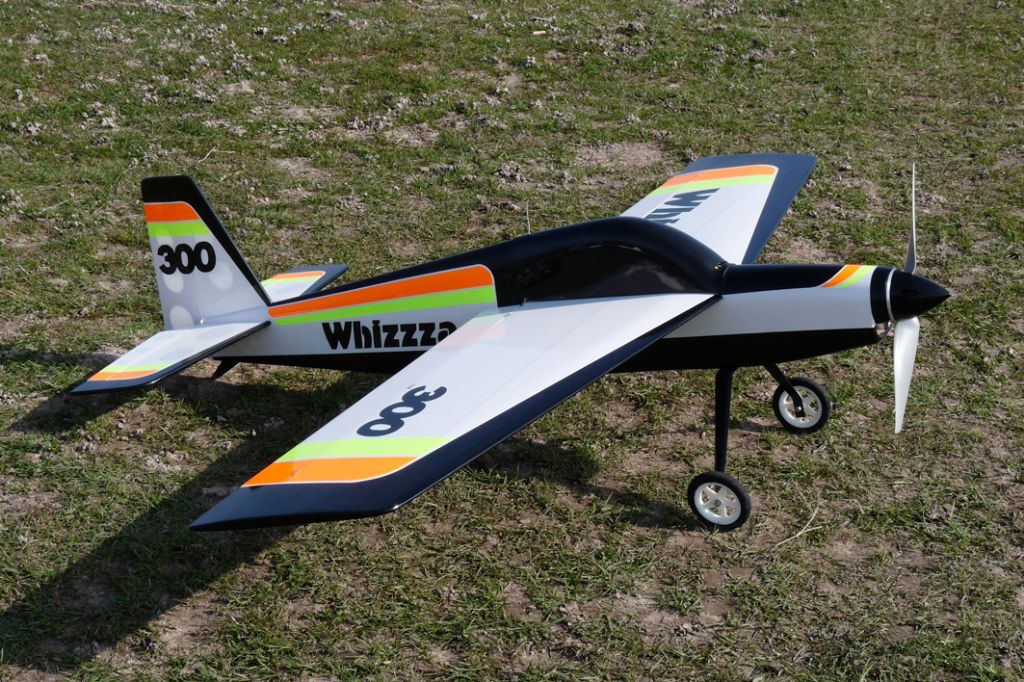
Good Luck!WordenLast week I ordered a wodge of standard Solarfilm to cover my Whizzza and was unaware of Solarfilm Lite. I have just looked at the Solarfilm website and I presume this is the same as Solarfilm Solite. -
I hope this is not viewed as the same as “how long is a piece of string”.
I am building the electric flight Whizzza from all balsa sheet, a RCM&E plan The wing is 10mm, the tail section and fuselage is 4.5mm with doublers here and there. I am aware that all up weight is important and it appears to me that there is some redundant weight due to the type of construction and would appreciate if the experts can indicate which areas to look at. I thought maybe small areas of the wing, fin, tailplane and fuselage could be removed. -
Posted by DH 82A on 20/11/2011 13:21:58:
J.N.. try this :- First, do not have a prop on the motor.Next, connect the three motor to ESC wires. Now plug in the ESC to your receiver motor socket. Now switch on your transmitter, and move the throttle to full power.Now, (and only now,) connect the battery. There should be a few "beeps", or a tune sound, now move the throttle to off, there should now be more beeps or tune.Pause a few seconds, then slowly open the throttle, and the motor should run, following the movement of the throttle stick. If the motor is running "backwards" , disconnect battery and swap any two motor to ESC wires.I am very gratefull for your help everything is now working as it should. Motor, ESC, Battery and Transmitter are all speaking to each other after I swapped over a lead. The long beeps or whistling noise I was worried about has now turned into a long beep that appears to be an audible warning that the system is "armed".Until I become more confident and experienced I may go for an external in series connection for the battery positive lead and connect/disconnect when in the pits.Thanks again.
-
Posted by Andy Gates on 19/11/2011 22:15:57:From reading your post, it sounds like the connections you are making are correct.The description you gave of the motor reactions sounds like the ESC needs to be programmed correctly for an outrunner motor with hard timing.Check the instructions and get the ESC programmed.The ESC is un-branded and I was not supplied with any instructions for any of the power train. The ESC is covered in heat shrink tubing, would it help if I stripped off the covering and included a photo in the hope that someone can identify it and advise accordingly.
-
Many months ago I bought a power train package along with all the bits to build my first electric flight model. The Motor is a BMI Spitz 85572, the ESC is unbranded but with a 40A sticker on it.Apart from the ESC battery plug, there is no identification on the motor leads or the leads from the ESC to motor. I am at the motor fitting stage and before parting the connections I labelled them up by fitting coloured heat shrink tubing. I must have mixed up the leads because when I powered up the motor it juddered around at slow revs until I could kill the power after about 5secs. I swapped the leads around which resulted in a whistle type of sound and I again cut the circuit after 5 secs.Can someone please let me know how I can identify the leads ESC too Motor. I tried a continuity tester but found that there was a circuit at any two of the 3 inputs to the motor. I then thought to connect the ESC to battery and Receiver and try to find a voltage rise at 2 of the ESC 3 outputs to the motor but gave up as I really do not know what I am doing. No visible damage has occured, there has not been any smoke or signs of heat.Thanks.
-
Sorry if this is covered elsewhere, I cannot find it.
I always understood that NICAD and NIMH batteries should never drop below 1.1v per cell. When I store my 4 and 8 cell NICAD and NIMH batteries I leave them alone until the voltage drops to 4.4v for 4 cell and 8.8v for 8 cell. It has just dawned on me that cells may be less than 1.1v and others more than 1.1v. I am not into measuring individual cells, as a general rule; what is the minimum battery voltage I should allow the above 4 and 8 cell batteries to fall to before recharging.
-
Posted by Seamus O'Leprosy on 15/11/2011 20:42:01:
jn have a look at picture 8 in the first post you will see the items either side of the "B" the mounting points on the fus could be better alsoYes I can see it plainly and it is were I expected it to be following your previous reply.
Mantua Fieseler Fi 156 Storch
in Warbird kits
Posted
By the way mine are dural not carbon, the kit was purchased this year