


jeff2wings
-
Posts
3,165 -
Joined
-
Last visited
-
Days Won
5
Content Type
Profiles
Forums
Blogs
Gallery
Calendar
Downloads
Posts posted by jeff2wings
-
-
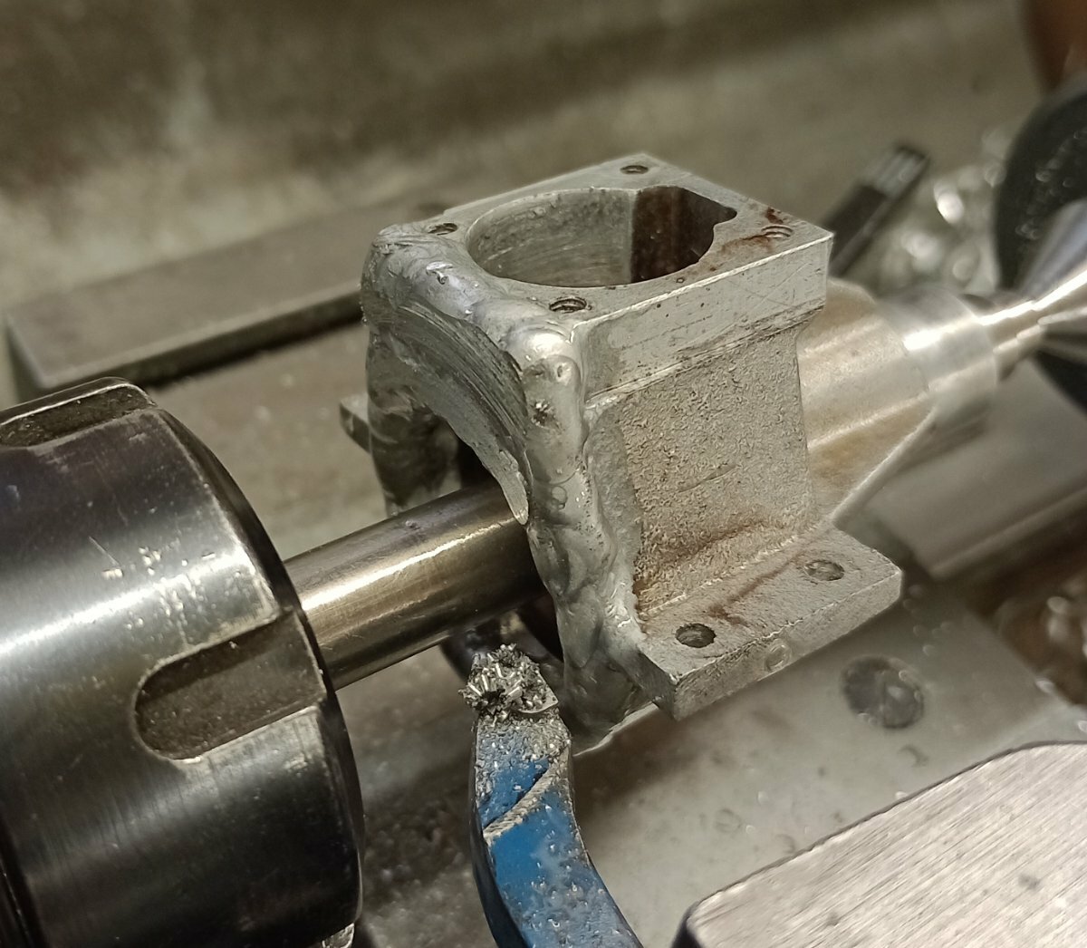
Repairing a crankcase is always a bit difficult particularly if it's diecast due to having things like zinc,tin,nickel etc low temperature brazing being equally as difficult as tig,the castings tend to be thin and it's easy to melt the hole lot! With tig welding you get blow holes from the zinc gassing off giving a poor weld/finish.That being said these are sand castings with LM4 and will take tig welding quite well and that's how I got out of jail this time !😄

made sure it's a nice loose fit this time
I ground the needle valve by hand on a sanding belt but the suggestion to use a sowing needle is a good alternative
-
Got my bearings from model fixings,be aware the early speed 61 had a 15mm crankshaft and later versions 17mm
-
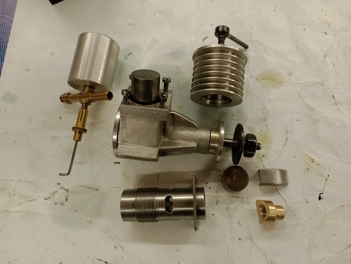
A cNot had a great deal of spare time but have made a bit of progress on the second Speary although I needed to do some reworking in order to correct a mistake I made and one made previously by the guy that I bought the casting sets from.
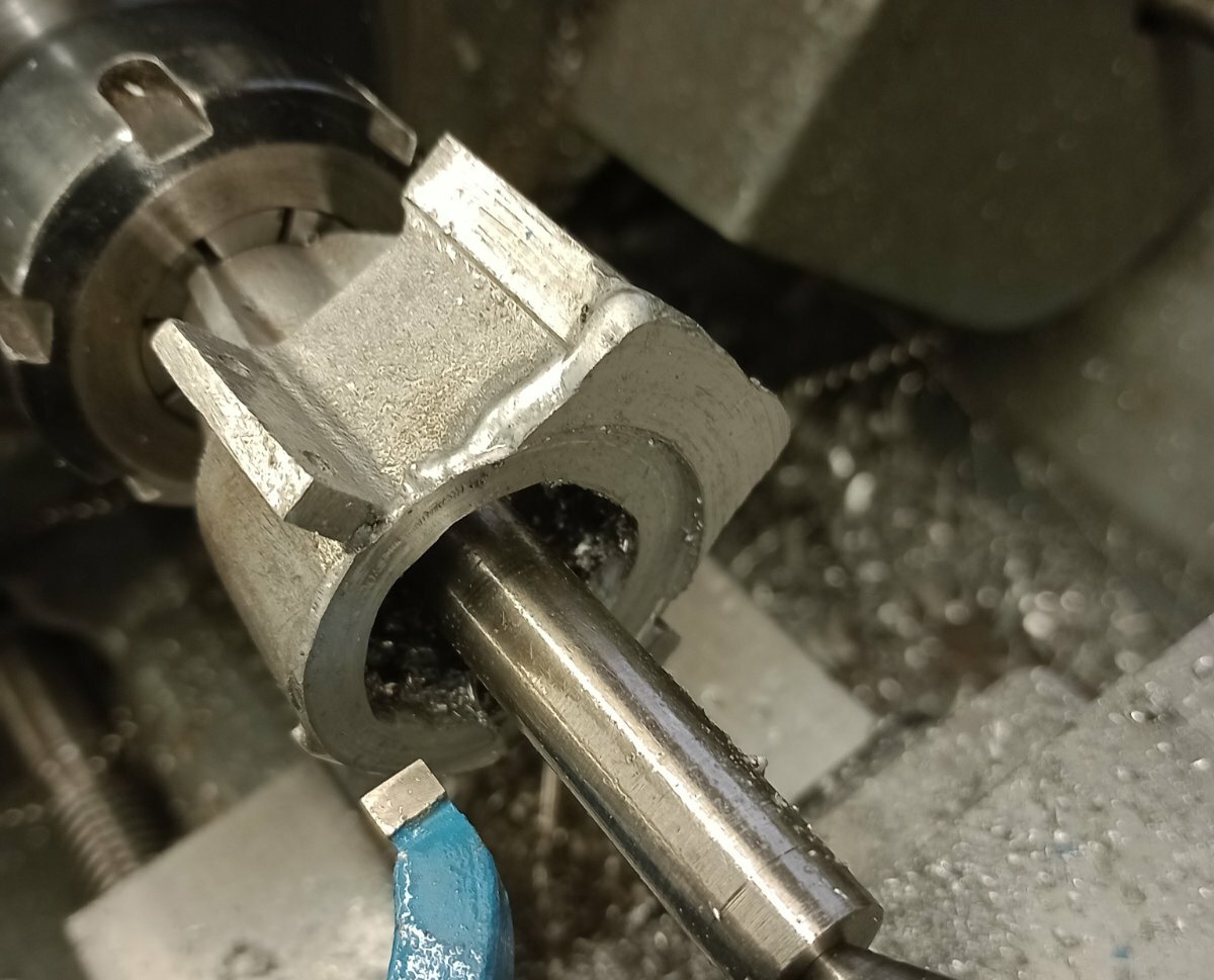
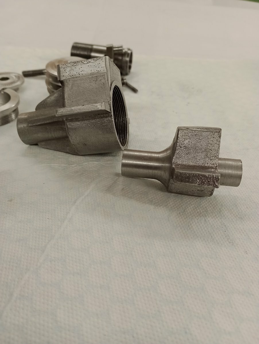
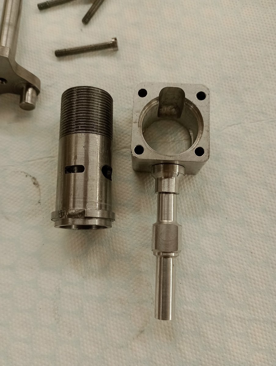
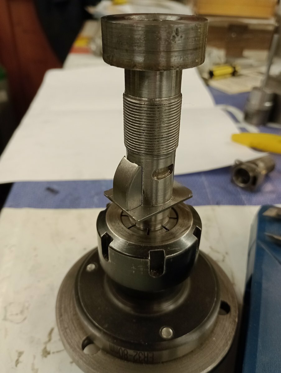
so wot happened was,I screwed the rear cover in and it got stuck, like proper stuck so I had to machine the hole thing out and then repair the damaged threads and the previous mistake by welding
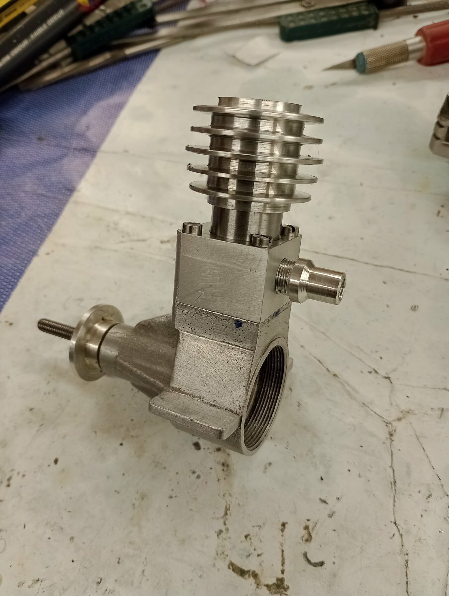
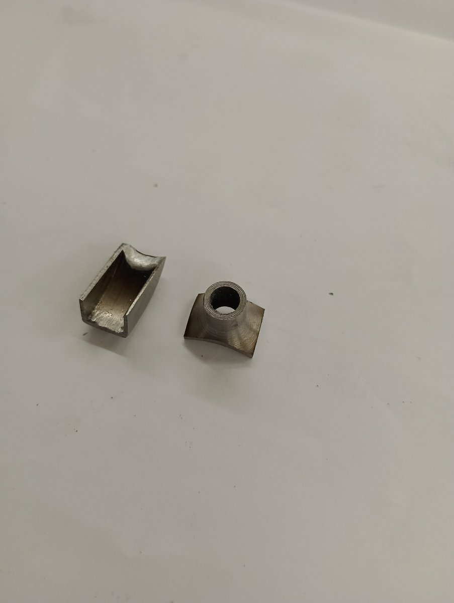
Once squared up I cut the recess and then brought it out to size and re-cut the thread ,then too take an actual step forward, soldered the intake and transfer on
also found time to fixthe broken and missing timer arm on the Ok super 60

-
 1
1
-
-
No,that would be this anonymous lump from Woking precision models (?)
The following pictures should help explain, basically it's based on the Swiss Dyno construction
-
1
-
-
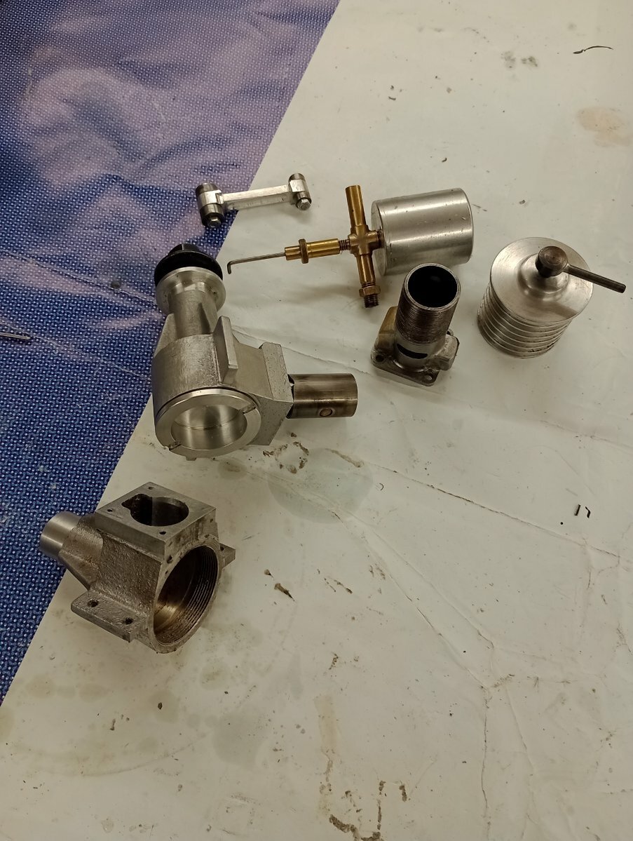
Intake tube done and exhaust ports opened out, once I've made the N/V it's onto the piston/liner that's the hardest and most important part of the build
-
Having finished making the six crankshaft blanks made a bit more progress with the Speary 2,0
-
2
-
-
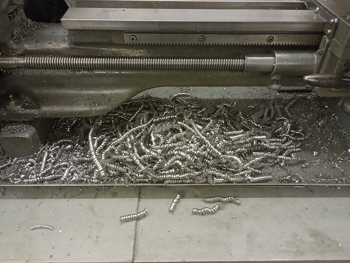
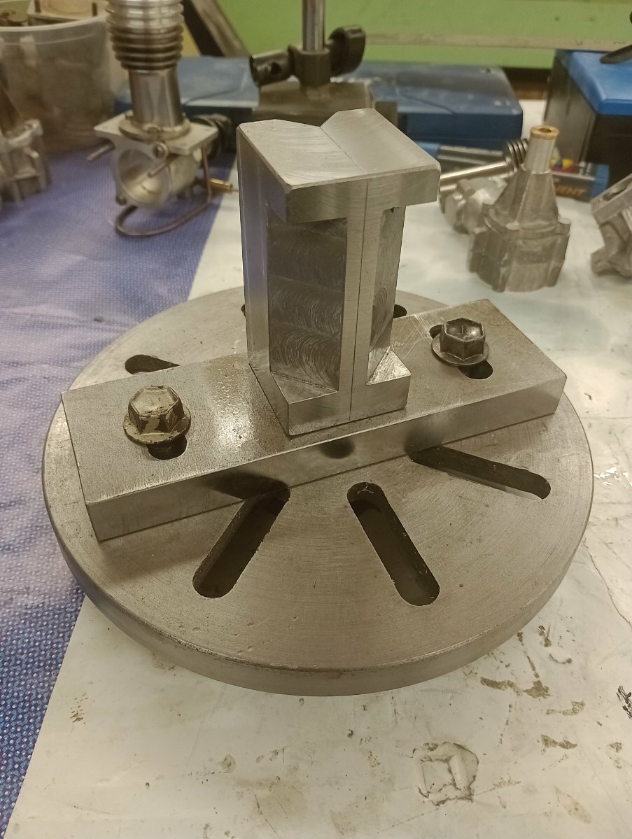
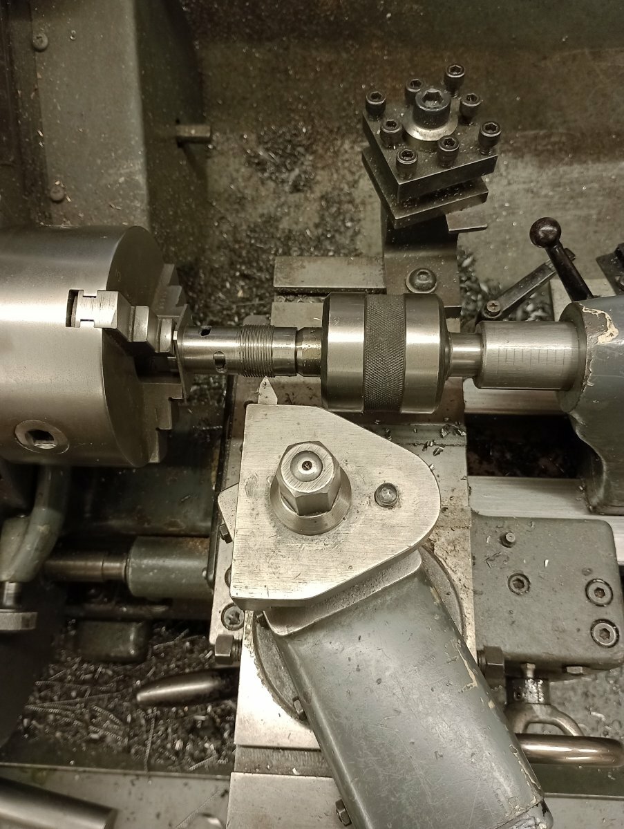
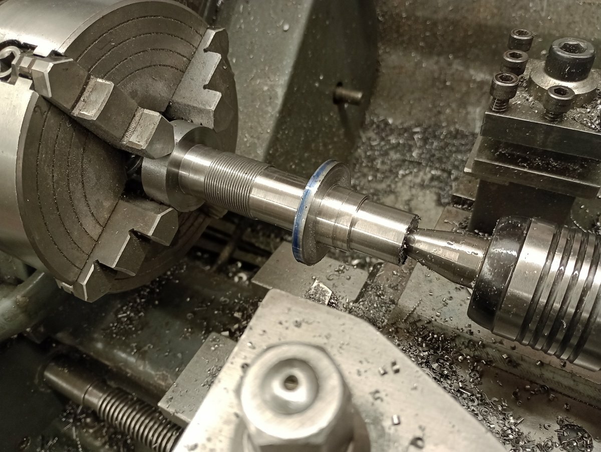
Yes you did doge a bullet there, lucky not too have it disengage from the chuck and damage it and more to the point, you!! Mounting the workpiece securely is paramount for safety and accuracy,also if you had machined the shaft (oversize) first it would have reduced the excessive jaw over hang.Also increasing the rpm is exactly the opposite of what you need to do to improve the quality of finish, a mistake most beginners make when starting out,myself included! I would recommend talking a step back and sort out the basics of work holding, tool grinding and getting the lathe running at the right speed range,you're up against it using a 100 year old lathe as it is(and good on you for doing so)
three crankshafts produce a lot of swarf
-
1
-
-
If you go on e-bay and look for myford accessories they sell a clip together belt,abit like the old motorcycle final drive belts before using chains,this should give you the chance of adjusting the belt length to suit
-
Speed,feed and depth of cut,l'm running 200 rpm 20 thou cuts and hand fed face cut,I prefer hss as it seems more tolerant of interrupted cuts and of course you can regrind/shape them too suit,btw when you put a cut on how do you measure it as there are no graduations on your cross slide ? are you using a dial indicator?
-
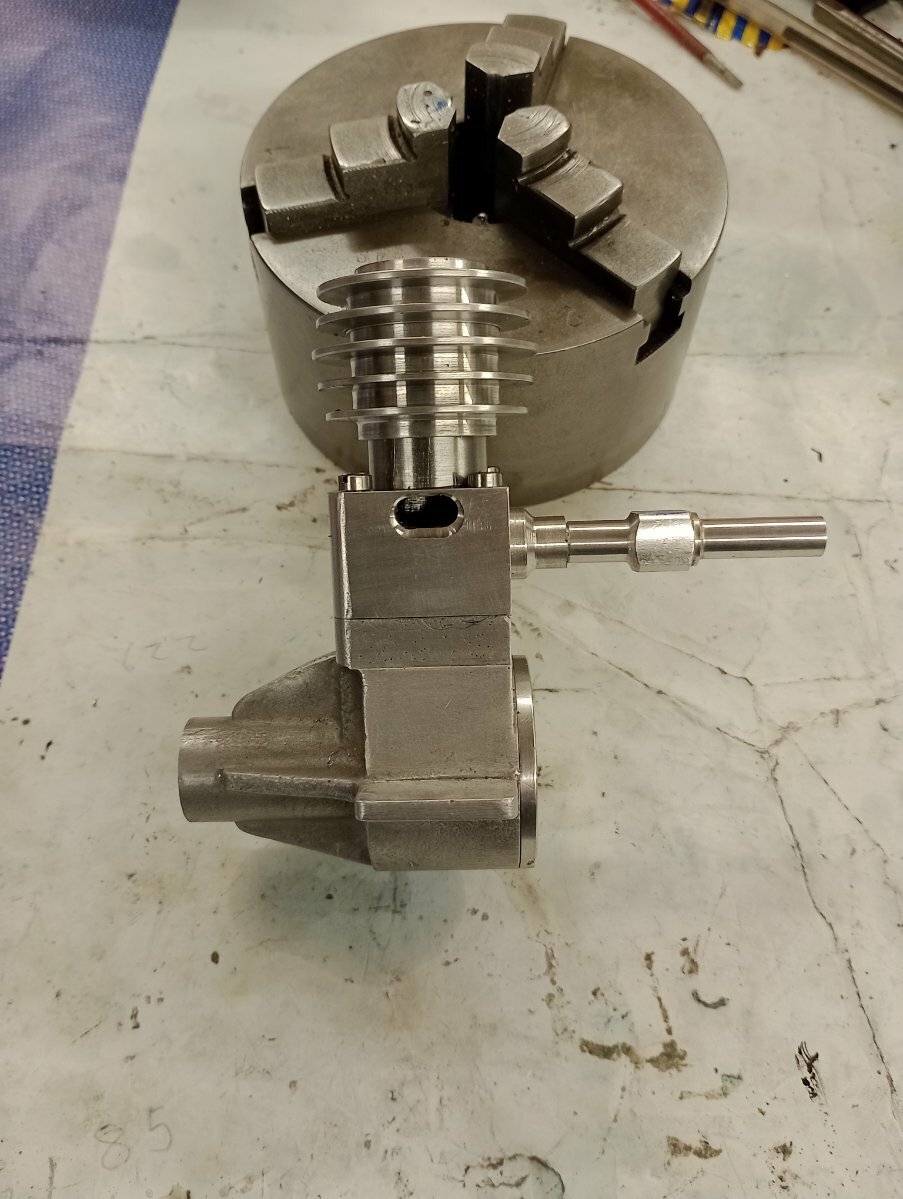
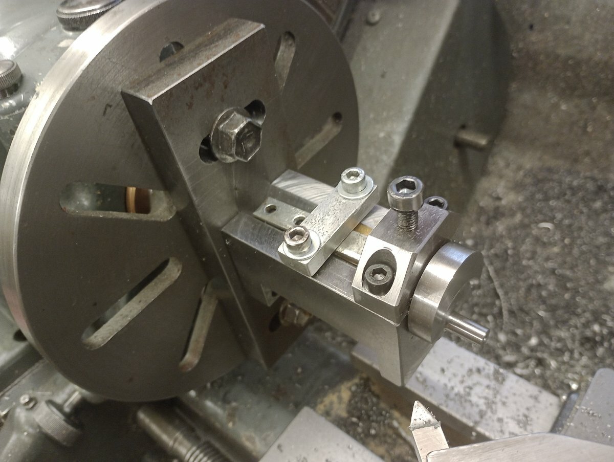
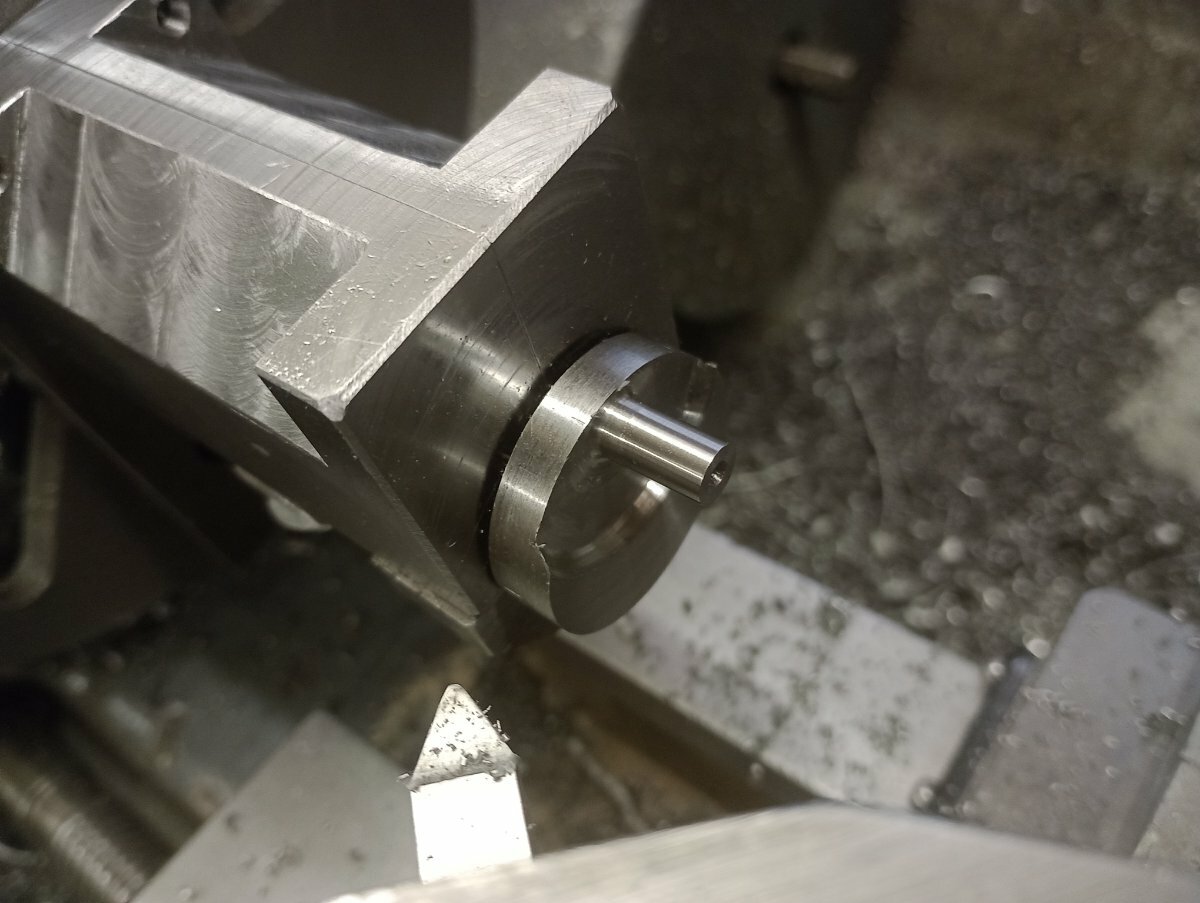
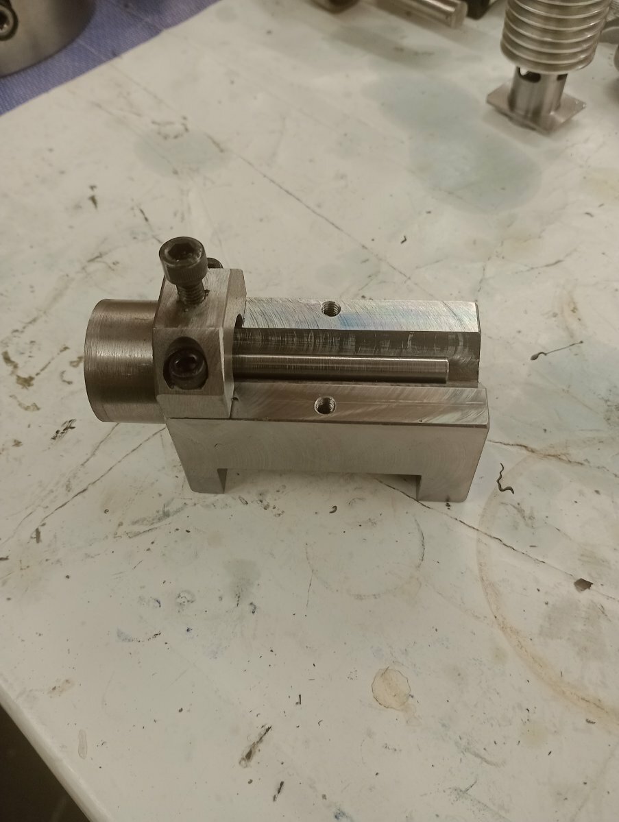
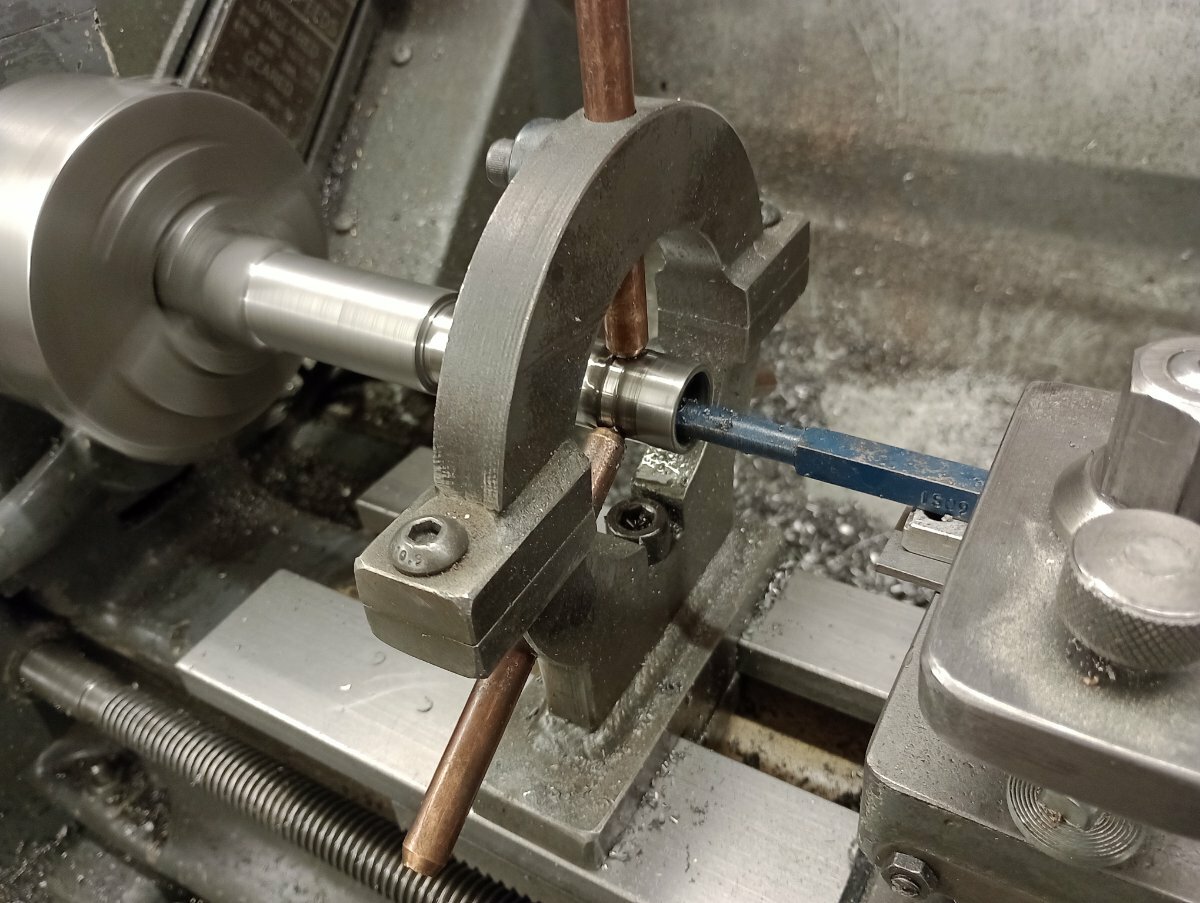
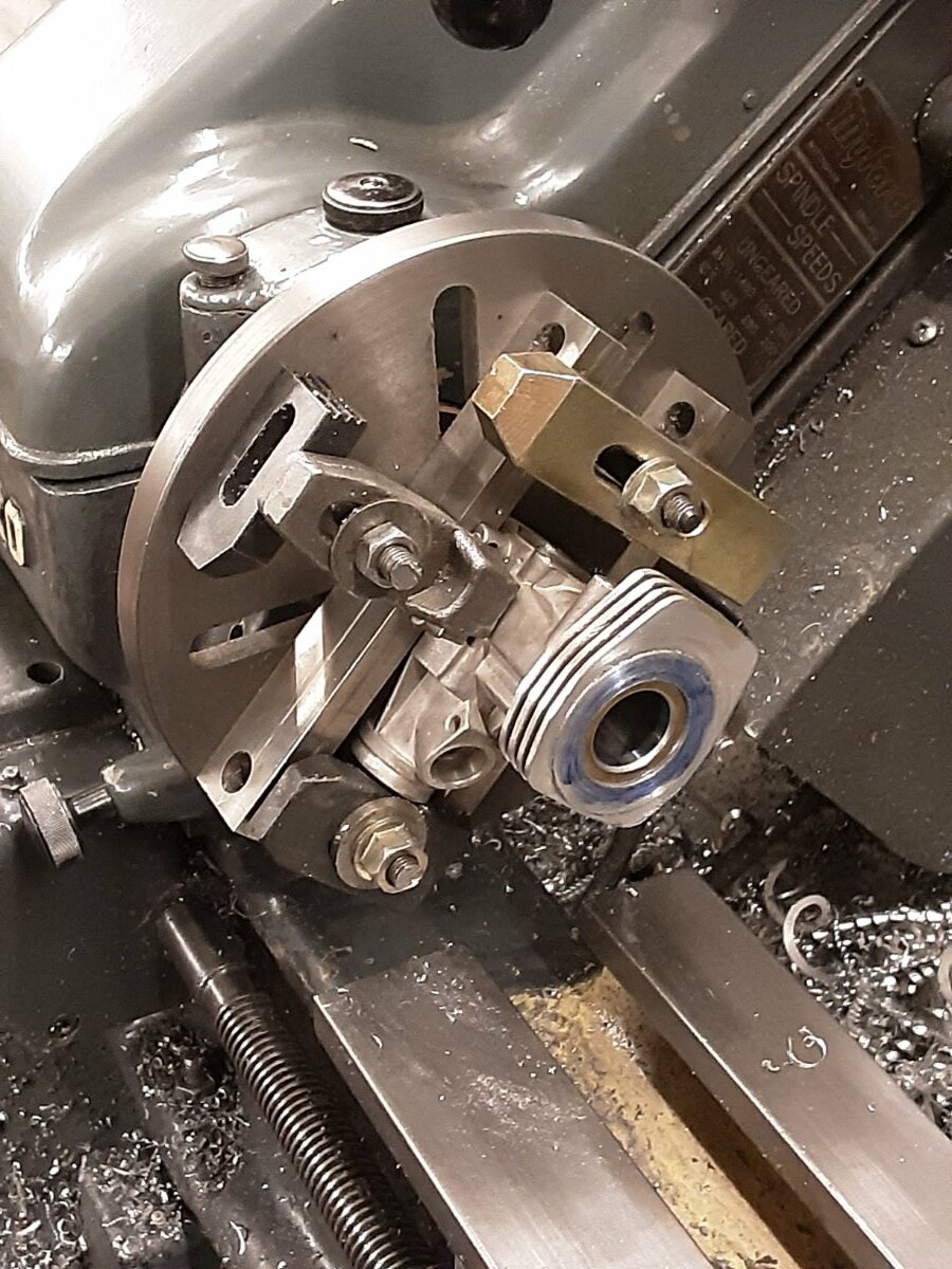
In total it took me 9 hours to make but the ease of setting up and surcurity of holding the crankshaft more than make up the expenditure of time.
One of three to be made for Westbury Atoms Minors
-
1
-
-
I would be careful with the cuts as you have very little engagement with the scroll on one jaw ,if the intermittent cuts are jarring the gears hard you can dampen the effect by using a piece of wood against the chuck, see page 4 of my thread
-
All sorted and ready to start making crankshafts!
-
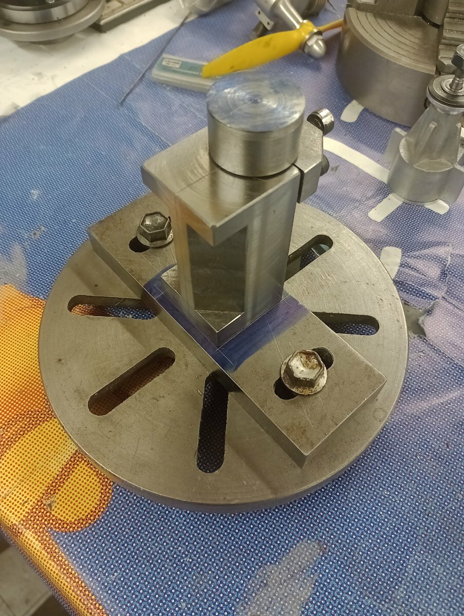
It's based on a design from Hemingway ,your best bet is to machine between centers unless you have a piece of 2" aluminium bar stock to make an offset fixture
-
Made some useful progress today, hopefully will have it completed tomorrow
-
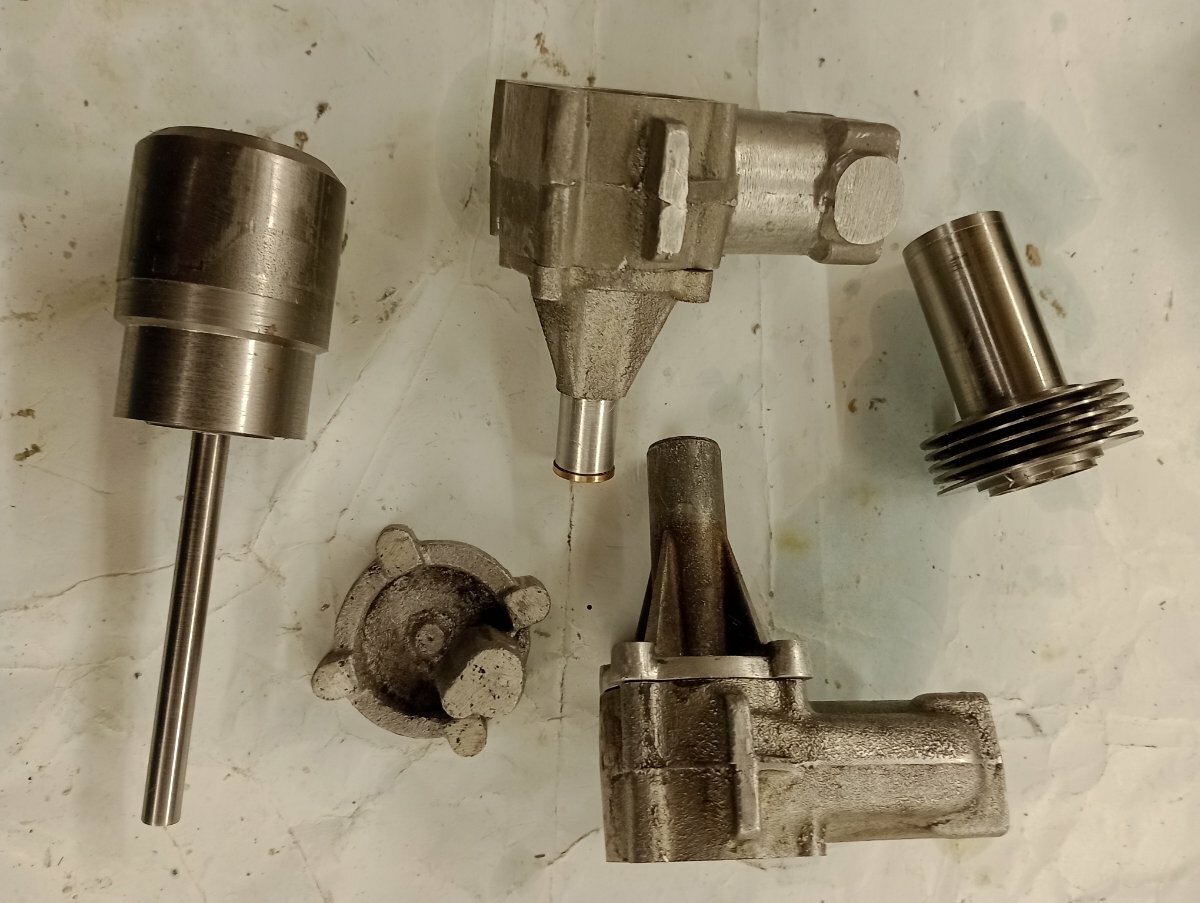
Had a free afternoon so spent the afternoon on the lathe, basically bringing the o/d to final size and parting off to length and then deciding that the thread form wasn't exactly too my liking and taking another cut.
also found the offcut of brass I was looking for so made another intake
Next I will need to lap the cylinder and size the piston and c/p to size after soldering the intake and transfer on
cylinder for second engine
boring to size
and as I need to make another crankshaft for the Speary, may as well make a couple for the Westbury atoms
-
2
-
-
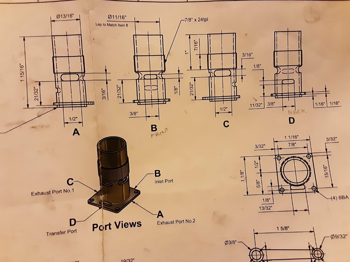
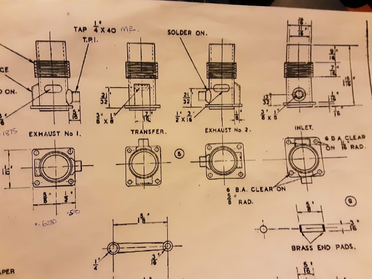
Hemingway drawings
Aeromodeller 46-47
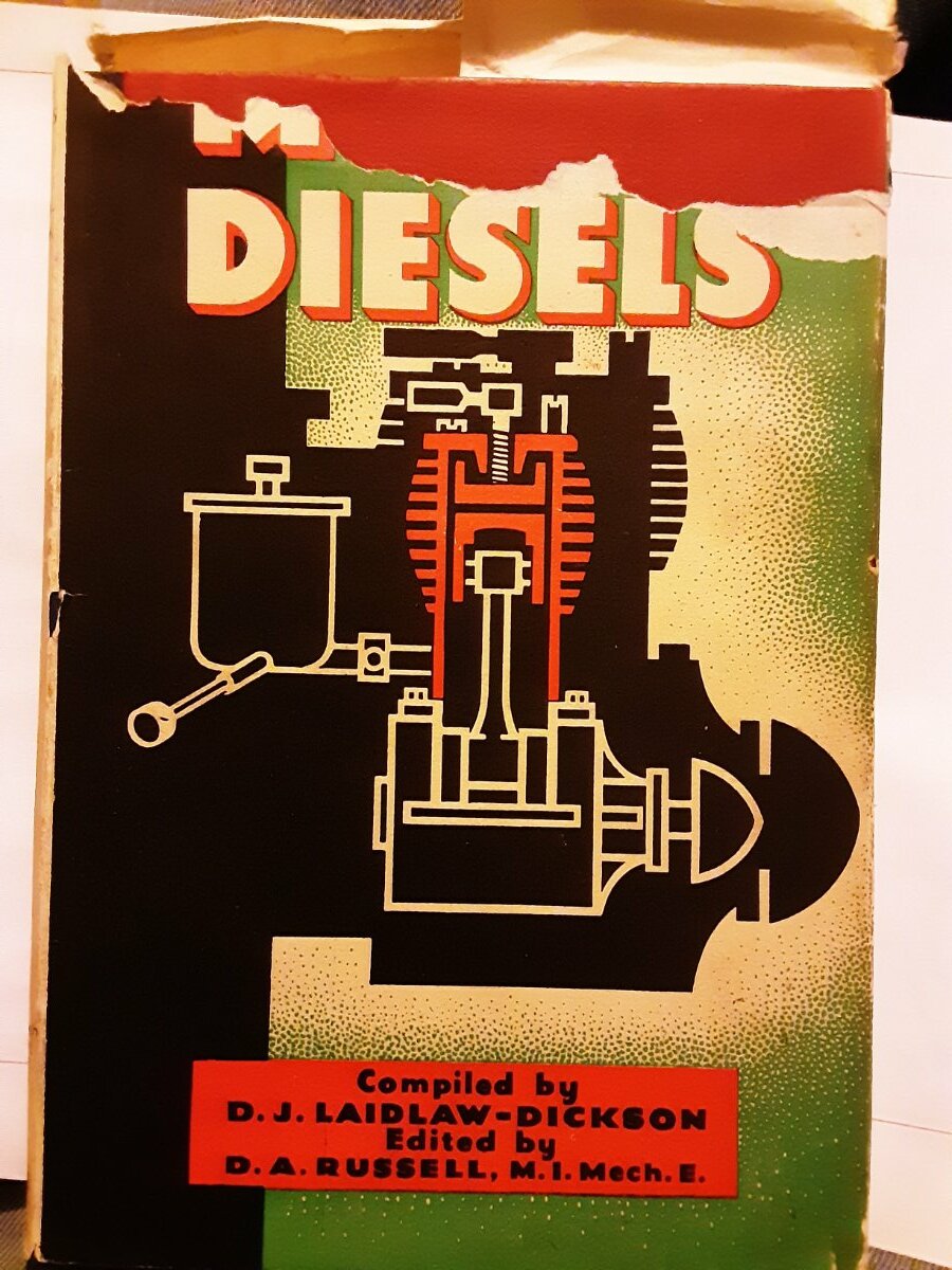
And the book they came from
-
Original drawings show transfer and exhaust at 21/32 to the centre of the port,Hemingway drawings measure to the bottom of the port, and inlet at 13/32 to centre
-
'Modern ' diesel engines, as in '50's onwards used this method for the transfer ports probably as it makes the production of the casing easier.
-
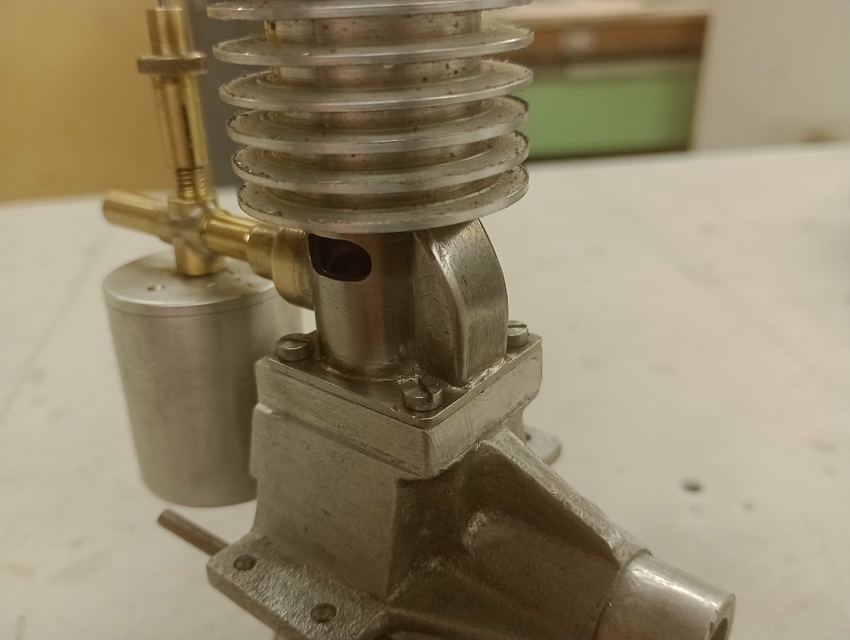
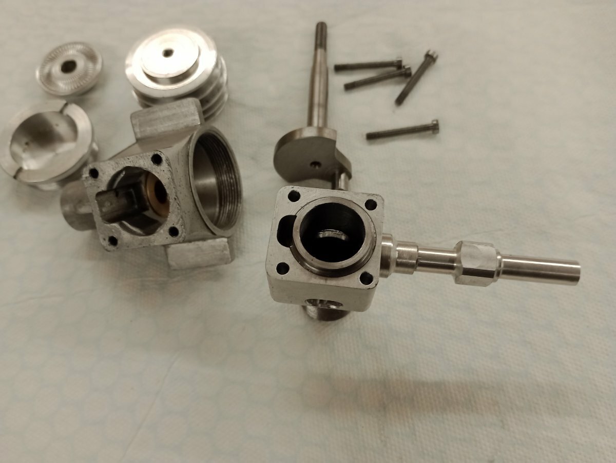
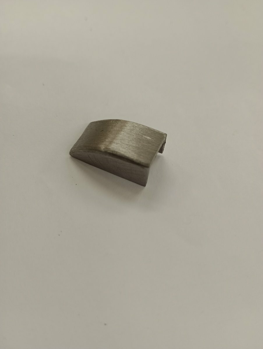
Found time to make inlet and transfer covers
would have preferred to make the inlet out of brass but didn't have any in the right size
-
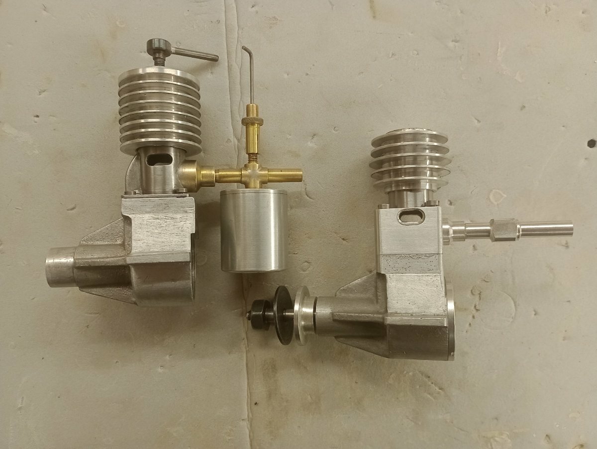
Taking a rest from balsa bashing (and the fact I'm about to fit a new kitchen 😐 ) I thought it time to revisit a old project, the Speary 5cc diesel.
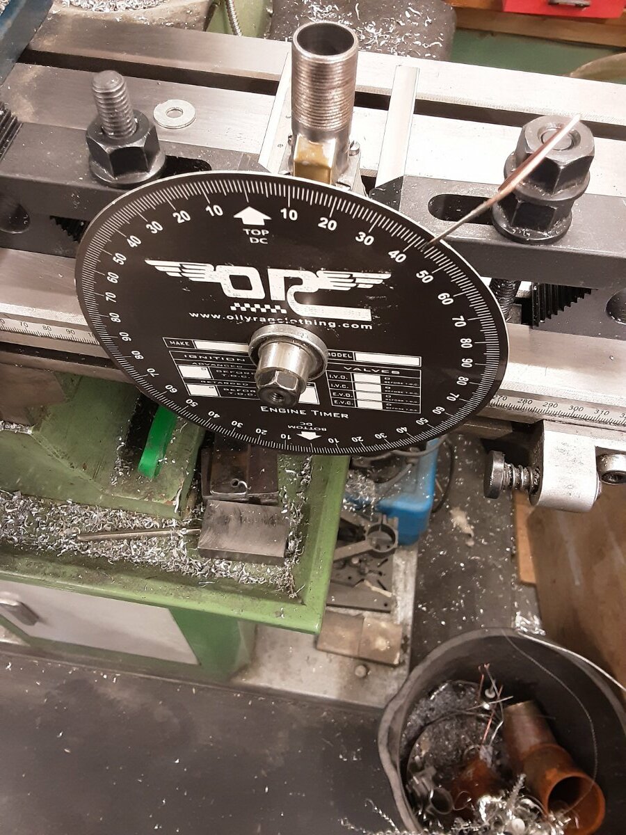
the engine did run but it was difficult to start and had poor running and power, so I stripped it down and checked the port timing.
the exhaust and transfer being well off ? Humm,how so,well I used the drawings from Hemingway not the originals from '46-7 and compering them there is a error in the later drawings, so back on the lathe then .
I also have another case that I'm going to use for a spark ignition version
-
1
-
-
Well you're making good progress particularly as the lathe is both basic and vintage (but perfectly adequate )you might find it useful to have a look at modelenginenews.altervista.org there is a full build thread for the Speary that I'm sure you will find useful .
In the meantime, I've a bit of catching up to do 😄😄
-
A face plate can be very good for odd shapes
-
1
-
-
Nice old pre-war Drummond, you have a face plate for it?
-
Just been checking the hemmingway drawings agents the ones originally published in 46-47 and there appears to be a difference in the transfer/exhaust dimensions, what drawings are you using?


14x6 or 15x6 prop
in IC Engines
Posted
It's quite capable of swinging a 16 " prop but not that one as it's for a modern petrol engine ,probably one about 20-25cc
second run on a 16x6 airflow wood 3,900 rpm with incorrect port timing, l will see what rpm my Mk3 wildcat and ETA 5 do on this prop