

John Rickett 102
-
Posts
240 -
Joined
-
Last visited
-
Days Won
10
Content Type
Profiles
Forums
Blogs
Gallery
Calendar
Downloads
Everything posted by John Rickett 102
-
Thanks for the compliments and pleased you liked the refurbishment blog. This is the first time I've attempted to record a build or repair sequence though might try another, I see Mr Fenton's efforts are popular and if it encourages people to get building, or help to stem the decline in building which is more to the point, it can't be a bad thing. Thanks for the tip regarding the use of fibreglass Manish, of course that won't burn so will be stored in the grey matter for possible use.
-
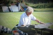
Hopefully, the problem with the inner engine exhausts has now been fixed. This picture shows the gap between the exhaust flexy pipe and the silencer stub; exhaust heat directly onto the silicon tube bridging the gap soon destroys it and if the flexy touches the tank, that too is melted. The simple solution was a short length of K&S thin-walled brass tubing, the silicon now forms a bit of a seal between the flexy pipe (which is slightly smaller than the silencer stub) and the brass tube but does not come into direct contact with the hot gasses. With there now being a metal bridge, there should be improved heat conduction. As an additional safety measure a piece of thin aluminium sheet has been glued under each tank. The 3rd flight was captured on video, still shaky in parts I’m afraid, but proves that the model has successfully flown again. The day was fine enough though a little choppy leading to the model being buffeted at times. The speed was kept slightly on the high side, I’m sure this can be reduced in better conditions to create a greater sense of realism but the greater aileron movement afforded by a one-servo-per-aileron installation showed that the model can now cope with a bit of turbulence. Resized, edited DH86 3rd flight.mp4 The little Lasers started easily and performed faultlessly, once again thanks to Jon Harper at Laser Engines for working his magic. From building three other deHavilland twins and multis, I’ve found there is a slight disadvantage (for the modeller) to their designs. The adoption of a single fin/rudder puts it out of the propwash. With the DH86 the outer engines are a considerable distance from the centreline, less than perfect engine synchronisation causes a tendency to swing on the take-off run which is difficult to correct with rudder alone. To counter this, each engine servo has its own channel with the outer engines slaved to the rudder. Full rudder output will advance the opposite outer engine by about 10%, ie right rudder will open the throttle of the left outer engine. The right outer engine in this example is not reduced by 10%; modern radios make this mixing very easy as Side A and Side B, in Futaba parlance, can be programmed independently. The cost of the restoration hasn’t been kept but it will have been a few hundred pounds, cheaper and quicker than starting from scratch I suppose. Cynically it could be described as mutton dressed as lamb, however I’m pleased with the final result and hope now that it has proved itself. it gets flown a bit more often than when first built. I’ll admit that it has been a more enjoyable project than I first thought, given that I reluctantly carry out repairs and this restoration was essentially just that. In building a model from scratch most are effectively prototypes as a subsequent one doesn’t usually get built to correct the inadequacies of the original, so a first for me on that score. This was the second of a two-model refurbishment I had tasked myself to do (the other was an equally old DB SE5) to prevent unairworthy models from taking up valuable space in my shed. In truth that was only buying a bit of time as now they are complete, I feel the need to tick off another attractive subject on an ever growing list. I’d better sweep out the workshop and worry how I’m going to squeeze another project into the shed.
-
Thanks for the compliments, its well appreciated. The little engines are bedding in nicely, even after only about 1/2 hours running, thanks to Jon Harper for getting them back to health. Here's a shaky bit of video, in my haste I had fitted a nearly flat battery into the camera instead of a charged one, so the camera cut out after a minute of so. The sound change when the exhaust blew can be heard as it comes overhead. Here's one more of Mike Mennell's photos from a different angle - now I really ought to get those homemade exhausts fixed so that flying can continue. 457295767_DH86PostRestoration1stFlight.mp4
-
Larger magnets have now been fitted to the (outer) tank hatches and spinner adapters, courtesy of Just Engines, have also been fitted. A bit of time was spent at the field getting the engines to run in sync, a job made much easier nowadays with the aid of point adjustable curves for the servo outputs. Each engine has its own servo and servo channel from the receiver so its possible to use one engine as a reference and adjust the servo curves of the other 3 using the (9) point adjustments in the AFR settings - I'm using a Futaba transmitter, though imagine that most comparable radios will have a similar facility though it might not be called Adjustable Function Rate (AFR). Mixed fortunes on the first flight. Son Steve was pressed into service as the test pilot and did a splendid job, the good news is it flew with only minor trim adjustments required, the bad news (not really), a silicon exhaust coupler failed on the first circuit and the flight had to be terminated. The inner engines each have a bendy pipe leading from the exhaust port to the homemade silencer. Short lengths of 1/2" silicon tube were used to make the couplings but the silicon cannot stand the exhaust heat for very long and one failed. This has happened a few times in the past and I haven't come up with an alternate solution, but one is needed as the fuel tanks are only millimetres above the exhaust pipes. When a silicon tube fails, the hot exhaust can be directed onto the bottom of a fuel tank and deform it. I'll have to think of another method to connect the two parts together which will allow a degree of vibration protection and also not allow any of the silicon tube to come in direct contact with exhaust gases. Fellow club member Mike Mennell takes excellent pictures of member's aircraft and lived up to his standard on Friday when these were taken.
- 162 replies
-
- 13
-

-
Thankyou for all the supporting comments along the way. Having stared at it for so long I'd almost forgotten the drab clothes it previously wore - hopefully its new bright finish will be an aid to my failing eyesight. I discovered yesterday during the engine runs that the magnets holding the tank covers for the outer engines were not up to the job; I think the old magnets will have to be cut out and replaced with stronger ones. Another fault to be overcome is the lack of thread remaining on the crankshafts when using aluminium spinners. I believe Laser Engines recognised this oversight some years ago and made the crankshafts a bit longer on subsequent engines so its no longer a concern. Shaft extenders used to be available from Laser but aren't listed anymore so perhaps a call on Monday to Just Engines is required.
-
Thanks for the support and the information Steve, yes that is what I wanted originally but being a novice at Youtube...... I won't be bringing it at the Easter weekend, the engines need to be set up which will take a while and then I'd rather do 2 or 3 test flights when there are few around.
-
Couldn't resist a picture with the wings fitted, before taking it apart again to put back in the workroom.
-
Thanks Graham, throttled back Lasers have a muted note, much less harsh than their contemporaries. About 18 months ago I bought a new transmitter, (Futaba 16SX). The features blurb said it had a multi engine function but whatever that feature is, is not in the manual. I was hoping it would carry the throttle cut to any other channel which was designated a throttle…but it doesn’t. In the end I got round the problem by assigning dual rates to each throttle channel, and only extending the range on one side. So now, pulling up the throttle cut switch, puts a high rate to each throttle servo and brings the throttle arms back just that bit further. I think I need to play with them a bit more to close the throttles completely - its all part of the pre-flight preparations.
-
If I've done this correctly, the link should show the little engines singing in harmony! The engines had only been run for a few minutes prior to this so there is still some setting up to do, but run they do and much the better for being overhauled by Jon Harper. The No:1 engine is really tight in the bore but even after this run it was loosening nicely. https://youtu.be/NPNurI4riOw
-
Thanks Ron, its taken a lot longer than originally expected but we're nearly there. Hope to have 4 dinky Lasers running by next week.
-
With painting complete its time to get on with the engines, tanks and undercarriage installation. The trousers completely enclose the inner engines so to allow for glow connection, a mini jack-socket is located just behind the cowl. With the cowl in place the male connector can access the female jack-socket. The one below is for the an outer engine, these are a bit more accessible so only needs a bracket to hold similar jack-sockets. The bracket then fits almost flush with the bottom of the cowl. In each case the glow plug connector part is a few turns of spiral wire with the lead soldered on and covering with heat shrink to take the load away from the solder joint. I used to use the old nylon wire curtain rods as they were a good fit on the plug posts of a few years ago. With a standardisation for all my Lasers to using OS 4 stroke plugs, which have a wider than normal post, the wire that is used for a certain type of stationery file folder, is a pretty good fit. Buy a couple of these if you find them in a stationery shop and you'll be set up for years! With just one turn snapped over the plug, they are not going to let go very quickly.
-

DB Sport and Scale Auster J1 Autocrat
John Rickett 102 replied to Danny Fenton's topic in Scale Matters
Sorry Danny, I've only just picked up on the question. The tape I used is from a company called Physical and its simply labelled as Sports First Aid. Its says its zinc oxide tape and latex free. Putting that into the search came up with this: https://firstaid4sport.co.uk/?gclid=CjwKCAjw0a-SBhBkEiwApljU0g3RbuTuy_ZffS68-sNzfI3rAhdGHARn-yS0a6kwHK2qHxgRPQZLHBoC63IQAvD_BwE It looks the same but can't be sure being out of the wrapper. The wrapper on the stuff I have says its distributed by Physical Sports Ltd, 17 Dam Rd, Barton-on-Humber DN18 5AS. If you are looking for a sharp saw-tooth edge, this won't give that. At first it looks to have a good edge but by the time its been stripped of adhesive and applied to a surface (I use fabric cement) the sharp saw-tooth edge is lost, but its passable from a distance. -
Thanks for the comments. Mostly it seems it was military aircraft which displayed fin flashes. If you look at restored WW1 fighters and later examples such as an Avro Tutor, the blue is in front. The change could, I suppose, have occurred in the 20s as aircraft just as the Hawker Hind and Hart can be seen with red at the front. Its blue, white and red now for this example so I will happily listen for the gnashing teeth of the aficionados.
-
Painting has been to a 2 steps forward, 1 step back rhythm. The silver and black cheat line went on ok except where it met the fuselage lettering. Too many junctions of paint masking caused bleed under the tapes and bits of the background to pull away. Much spotting with a tiny brush has more or less rescued it but I will think twice about a two colour cheat line through lettering next time. I quite liked the fin flash from the earlier scheme so thought that could be retained, but this time put the blue to the front as British aircraft used to have it. The swap to red at the front was prior to the start of the war but I couldn't find out quite when; seeing as the model can date from 1934 it could have had blue at the front! The Civil Air Ensign is a waterslide decal produced on clear craftycomputerpaper inkjet paper. The ensign is wholly appropriate being a British aircraft and I thought the colours matched the aircraft finish well. The ensign was designed quite simply using an Excel spreadsheet with a sourced Union Jack from the web. The design was then imported into Word to enable it to be scaled to an appropriate size Setting the printer to 'photo quality' produced nice intense colours......a small success. The rudder and elevator closed loop cables have now been installed - a day and a half job feeding 6 cables through the fuselage and not getting them crossed in the process! The next job, when the weather allows, is to complete the painting of those parts of the cowls where they extend onto the fuselage and wings
-
DB Sport and Scale Auster J1 Autocrat
John Rickett 102 replied to Danny Fenton's topic in Scale Matters
Danny, the tapes can be bought in various widths, typically 2", 3", and 4" but all have the same pink pitch. Below is a short length cut across with standard pinking shears, these have a 5mm pitch, so the difference is barely distinguishable. Overlaid on the tape is a strip of sport first aid tape (see packet). The tape is coated with adhesive but if unwound and steeped in thinners, all the adhesive is washed away leaving an open weave which will take dope very well. I've recently recovered a DB SE5 (which wouldn't have had pinked tapes) however the ragged edge result is passable for the sort of pitch you'd expect on a 1/5 or 1/4 scale model. While they don't look as smart as the Mick Reeves tapes, its a much cheaper option and once doped and painted, the casual observer probably won't think its out of place. The best stuff to use was 3M Hair Set Tape, this had small pinked edges and was ideal for 1/4 or 1/5 scale, unfortunately its just about unavailable now, hence the nearest alternative I've found which is first aid tape. Hope this helps! -
Thanks for the compliment Stu and pleased you liked it. The project has dragged on for quite a while now, I didn't realise how much time it would take, but as they say there's light at the end of the tunnel, which hopefully we should emerge from in a month or so.
-
Some respite in the gloomy weather allowed the red to be applied to the bottom half of the fuselage. The paint was left to cure for two days before removing the letter borders and I'm now satisfied with the result. I gave up on the idea of re-applying those parts of the masks removed prior to painting as they inevitably stretch a bit so cannot be repositioned exactly. I'll run off a second set and then overlay those parts that need to be covered up again to enable the black to go on - it will be interesting to see if the masks can be repositioned perfectly............. In painting with matting agent added, I've discovered that the paint needs to be applied absolutely consistently otherwise there are differences in the finished results. If for example one area is given more coats or applied wetter, the matting effect is substantially reduced, unfortunately that's what I've ended up with in places. Oh well, that's life. I think one of the endearing aspects of the hobby is the unrealistic expectation that the next model is always going to be an improvement on the previous!
-
With the weather forecast as it is, there's not much chance of any painting but progress can be made with the rigging. With the wing joiners only being short lengths of piano wire, the rigging forms an essential part of the structure. All the flying and landing wires are made up from Mick Reeves supplied items with each flat wire consisting of a left and right hand clevis. Short lengths of stud are provided which have to be silver soldered (butted) to the stainless steel rigging wires. The advantage with this system is that once complete, the clevises do not have to be removed from the model, the flying wires can be screwed in or out to assemble or disassemble the model - it saves having to work on your knees at the field with tiny screws to contend with. If you are going to use this system make sure you threadlock the 2mm screws which attach the clevis to the anchor otherwise some of them are bound to fall out. Silver soldering the flat wires to a stud is not difficult but with each stud being M2, they are quite fiddly so its best if you have three hands, unfortunately perhaps I was not born that way so I had to devise a way to hold everything together based on the use of two vices. First, using a small square file, make a vee notch in the end of the stud, this will keep the wire central while soldering. I use a length of brass tubing which has been tapped M2 left hand thread at one end and right hand thread at the other. The stud is screwed into the tube a few turns and then the tube is clamped in a vice. A length of silicon fuel tube slipped over the brass tube minimises heat loss. The wire is then pushed into the vee notch and held in position using the second (mini) vice. The screws holding the mini-vice are not fully tightened so that a degree of adjustment can be achieved to make sure all is straight. After that apply a dab of flux top and bottom and then heat with a blow lamp using the lowest possible amount of heat. The idea is to get the joint just turning red, at which point the silver solder can be applied and a bit more heat (moving the lamp slightly closer to the workpiece) should see the solder flow over both the wire and the first few threads. Once cooled the joint can be cleaned up, I use a Dremel drill with a rotary stone attachment to flare any excess solder and to polish a finish. Two wires done today, only another 7 pairs to go....plus the tail bits.
-
After rubbing down again and repainting with the white basecoat, another attempt was made. This time I thought I would try one of each size of letter and see what the wing letters would look like with a red border. I wasn't keen on the result, the paint had lifted again when I tried to remove the mask, probably because I tried to remove it too early so I left it for a day and then the rest of it came away ok. Also I didn't really like the border so will paint the wing letters black only, it will certainly save on the two stage painting process. The fuselage letter I was satisfied with this time though there are small areas where the re-masking wasn't exactly right which has left some white bits, if this happens again it can be touched up with a airbrush or very small paint brush. I made the mistake of not removing the mask from the top half of the G bar, note to self 'don't make that mistake on the fuselage side'! All of the white areas have now been painted, including the wings, so as soon as the weather improves to allow painting, the red will start to go on. I was hoping to have the model ready for the LMA static event at Cosford next weekend but I'm sure now it won't be complete, however the events which were previously held at Gaydon and this one replaces, were supposed to be a work in progress show, so I'll take it anyway.
-
Thanks for the support Manish, but I'm not happy with the result, there are bits of black border missing in quite a few places. I've learned a few lessons which is what this hobby is about so hopefully the next attempt will be better. Jersey Airways Ltd, now mostly obliterated with the latest mask was a success so I'll use those masks without alteration, but then one colour is quite easy, its trying to do multiple colours where one mask has to overlay another when the errors creep in. People say that you can't see any of it when its in the air, which is true, but all models spend most of the time on the ground and with the eye being naturally attracted to detail the little bits ought to pass muster. If at first you don't succeed......
-
Painting the test panel proved to be a frustrating experience. I think anything that could go wrong did, but at least it was better to practice on the panel rather than to commit straight to the airframe. For a start the black borders are too small at 1mm and don’t provide enough emphasis to the letters, these are 110mm so that’s a less than 1% border. I’d experimented with the dash with a thicker border (2mm) which looks better although I think 2.5mm will be better still. Also, in some places the thin border didn’t adhere sufficiently to the paint below and consequently lifted when the masks were removed. This may be partly due to there been so little surface area to gain adhesion. There is quite a lot of paint bleed and this on a smooth panel so undoubtably it would be worse on a textured surface. I’ll have to pay greater attention to making sure the masks and any tape are well pressed down. I hadn’t rubbed down the paint to provide a key as it would have meant that some of the finished white would have shown the scratch marks of keying, and neither did I clean with panel wipe so there could have been greasy finger marks which prevented the masks and paint from adhering. In painting the juxtaposed colours, starting with a white background, the red letters have to be re-masked in order to spray the black border – getting the masks into a precise position was incredibly difficult. At this point everything is red so there is only the raised edge of the adjacent mask to work to. Increasing the width of the borders will make any location errors less obvious. Another problem is gauging when to remove the masks, too early and the wet paint flows slightly, later when the paint is dryish but tacky, it tends to leave string marks when lifted. If it’s left to be touch dry there is an edge which doesn’t smooth out. The last leaves the cleanest finish but unless there’s going to be a final clear coat, the paint can’t be rubbed down due to the unsightly marks that remain. It would have been much easier to just paint black letters but the good news is I like the effect and think it provides a period look. As an additional experiment I’m trying one of the wing (black) letters to see what that looks like with a red border, It’s worth persevering, at least for a little while.
-
A bit windy yesterday for spraying so picked up some dust, however at a 30% mix, that looks about the right sheen and a decent contrast to the gloss
-
With the test panel being curved its impossible to catch the light for all test strips but having now tried mixtures at 25%, 33% and 50%, I think 33% is the nearest to the desired effect but perhaps could stand a little more gloss, not as glossy as 25% though. I'll rub down the whole panel and apply a 30% mixture before trying lettering on it.
-
Thanks for the information Stu, I do buy the paints from a motor factor - Humberside Paints. They have suggested they can mix it but first I've got to determine the degree of sheen required. Once that's found I will probably get them to mix it so as to maintain consistency. The disadvantage of premixing is its expensive and the unused paint will always be matt. In the past I've used whatever paint I could find in the colour I wanted, regardless of gloss, matt or satin, and then given the whole model a coat of KlassKote clear to bring all the sheens to the same consistency and to act as the fuel proofer. That works for so long but inevitably the fuel will find an edge and attack the paint below, also some paints are attacked immediately by the solvents if they haven't had sufficient drying time (which can be weeks) so for the past few years I've been using 2K paints and primer and trying to reduce the gloss by applying the paint 'dry'. Not being a proficient sprayer means the results have been inconsistent so this time I thought the matting paste approach might work.
-
Thank you for the kind comments, and I agree the T31 engine is a little work of art, well done. The tail section has been rubbed down as best I can. Its fairly easy on the sheeted parts, not at all easy on the open fabric areas. I wanted to get rid of as much dead weight as possible although I think its probably a waste of effort, the amount of paint that can realistically be removed is minimal. The whole model has now been given a coat of 2K primer. When I started this job I thought that the tail was good enough not to require recovering so I'd just have to get round painting with the rudder and elevators in situ but perhaps not recovering was the wrong decision as the primer has shown up some damaged bits... I'll live with it. Each engine bay has now had a coat of primer and a grey 2K topcoat. If this doesn't make a barrier to the fuel, I'm giving up and trying flat field soaring. The engine bays are not particularly pretty but better than before. Looking rather drab even in the afternoon sun and recuperating from a mini disaster - the wind blew the fuselage off the trestle. Not much damage, just a puncture in the covering underneath but annoying nonetheless. A small patch was applied, and given a couple of coats of dope followed by some !k filler. With a bit of luck it will hardly be visible once the topcoat is on. Before the final coat can be put on, there are two little problems to solve. The first is to reduce the gloss of the paint to better match painted fabric. The second is to decide where the cheat lines should be and where the fuselage registration letters should be positioned on the cheat lines, so a bit of experimenting was called for. An old test panel was rubbed down, given a coat of primer and then a topcoat of the white; actually its not white, its the lightest shade of grey I could get mixed. I prefer this as it looks less stark than brilliant white. The lower part was then painted with matting agent added. The data sheet said to use it at a ratio of 1:2, though to me it looks too matt for the purpose. I'll try reducing the ratio next time. Once the correct degree of matt is arrived at, the plan is to use the test panel to see how well the lettering masks will adhere to a matt finish and whether there is any paint bleed under the masks.
