-
Posts
4,957 -
Joined
-
Last visited
-
Days Won
10
Content Type
Profiles
Forums
Blogs
Gallery
Calendar
Downloads
Everything posted by Gary Manuel
-
Servo lead cables exitting the wing. The short ones are the flaps. The trailing leads in the fuselage will have the flaps with the longest lead and the aileronns shorter, which will prevent incorrect connection as the aileron trailing leads won't reach the flap leads. Rubber grommets used at the exit. Prevents vibration damage, covering peeling away and also prevents the leads from sliding back inside the wing during transportation.
-
Wing servos first fitted and roughly set up prior to radio fitment. All four servos are Hitec HS5925MG and fittings are Pete Tindal blue series. Ailerons with servo in approximately the centre position - servo arm at 90 degrees and aileron in the neutral position. Flap servo with servo in approximately in the centre position. For the benefit of anyone who doesn't know, flaps are set up differently to ailerons (and other) controls. The servo arm is fitted to the servo whilst in the centre position with the arm offset as shown and the flap partly operated. This is for two reasons: 1. The movement of the servo is from the neutral position downwards only, so this position is in the centre of its movement. 2. The servos holding strength is weakest when at 90 degrees to the push-rod and strongest when at a smaller angle. i.e. it would be impossible to turn the servo by pulling or pushing the rod with the servo arm in line with the rod (zero degrees) because there would be no turning moment. The flaps will have the maximum force (air flow) when at maximum deflection - this is when the small angle is used to effectively "lock" the servo in position. The 90 degree servo angle when the flap is in the neutral position is not an issue as the air force is low (similar to other control surfaces). Flap fully operated - servo at a narrow angle and flap fully deployed. Flap in the neutral position - servo in the 90 degree position (with the servo towards the end of it's movement).
-
These is the crimping tool I'll be using. This is what the dies look like And this is how the crimps need to be inserted before sliding the stripped wire in and squeezing. Not obvious to look at. The open end of the crimp goes into the concave die with the wire entering from the marked side. Wires crimped First one clicked into place and second one ready to be pushed in - note which way round they go, and which colours go where.
-
Wing servos next, but first I need to extend the servo leads for the ailerons. The Flap leads reach the exit holes OK, so won't need extending. Extension leads soldered together to make up the required length and insulated with tape. And then tidied up / vibration proofed with heat shrink tubing. Hobbyking servo lead crimps. The crimps come on strips with the plastic surrounds separate: Note that there are two types of crimp / surround in the set. The female plug - as used on the end of the servo leads - These are the ones I'll be using: And the male receptacle - as used on the receiver / receiver extension leads - I won't be using these here.
-
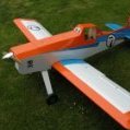
Dusty needs some way of controlling him, so here goes...... Nice short Pete Tindal blue series controls all round - even matches Dusty's trim colour Note the steerable tail wheel assembly now fitted. JR591 servos used for the two elevator halves. Pete Tindal blue series pull-pull for the rudder. Cables look as if they are bending and rubbing on the fuselage side as they enter, but it's an optical illusion due to the tapered fuselage. Wire run is actually quite straight. Hitec HS5985MG servo inside the cockpit, used for the rudder. Edited By Gary Manuel on 22/04/2014 23:45:30


