

Nick Somerville
-
Posts
902 -
Joined
-
Last visited
-
Days Won
7
Content Type
Profiles
Forums
Blogs
Gallery
Calendar
Downloads
Everything posted by Nick Somerville
-
Great maiden. 14kg is a very good weight for the model. Mine is 16kg but still not heavy for the wings area.
-
 Martin’s beautiful book on The Worlds Vintage Sailplanes was like a bible to me back in my scale glider modelling years.
 -
So true. I used to cut these parts with my fretsaw but it ate blades for a passtime and I hate it when they break when cutting. Drilling and filing is tedious but preferable. Thanks for the encouragement.
-
Aileron hinges in the lasercut parts kit were ply and not durable enough, so 2mm glass fibre sheet has been employed. After marking out a dremel was used to drill around the shapes few drilling and then they were sanded and filed to shape. One if those tasks that you inky want to do once in a while!
-
I have been a bit confused (usual) regards the flap construction and although the upper shroud is now in place I have made a start on the ailerons whilst the brain fathoms the flaps. Here’s one of them. Pretty straightforward but as the full size had fabric covered ailerons it’s a bit of a work around. Sheet underside for rigidity and a laminated trailing edge with carbon tow inset and a 1cms strip of G10 below. Nice and stiff. I can simulate the rib stitching and pinking strips on both sides once covered, though the upper side will be more realistic. Still to add are the reinforcements for the hinges. Below are the upper and lower wing areas with the flap shrouds. As previously mentioned this is a G10/balsa/carbon laminate to cope with the large overhang.
-
Brilliant, clicking outside the box instead if ‘go’ sorted it. Thanks for all of the advice.
-
I tried that but pressing go doesn’t activate a change
-
Thanks for reply both. Martin, yes the FW190 thread is one of them but when I look at it from ‘My Activity’ there is only one page of the thread showing. The settings show activity for past 365 days and cannot be set for a longer past period. However, even at 365 days there are lots of posts not showing as I had documented the detailing and painting of the FW 190 from January to April last year. Leccyflyer: When I click on my activity it doesn’t show either my Sea Fury build or the previous P47 as it used to. Not surprising I suppose if the default settings is for 365 days. I would like to access them though.
-
As an occasional user I confess to being rather slow in understanding changes made to the forum. I recently wanted to look back at one of my scale build threads to extract some information and photos for a fellow builder, but am now only able to see things posted to a max of 365 days ago. Is there a way to view any of my thread postings prior to this timescale and if so how.
-
The centre section was jigged up and the outer panels were framed up and top sheeted one at a time. I do enjoy sheeting! The ailerons will be built up separately along with the flaps areas. There is a large overhang where the flaps separate and are hinged so I am sheeting this area separately with a carbon balsa laminate for rigidity.
-
Finally back in the workshop after an enforced break due to a long overdue bathroom renovation. Although I am still waiting after two months for my retracts to be manufactured by Robart I have been kindly lent a set, which means I can get on with the wings. A 500mm x 50mm aluminium tube and phenolic sleeve are being employed for a two piece wing. The belly pan will need to be made removable for attaching them but I think prefer this to a three piece wing. I am at the stage where I am ready to sheet the top of the centre section. Once done I can frame up the rest of the wing on the board with the centre jigged up for the dihedral.
-
Praise for SLEC
Nick Somerville replied to Dean Clarke's topic in R/C Retailers / Distributors / Manufacturers
Not so long ago I purchased a short kit for the Bates 1/5 Hellcat cut by Slec, who have taken on the Bellair range. Delivery after order was as ever prompt, along with a fabulous selection of strip and sheet material neatly packed that I had also ordered. Now a few weeks ago I made a start on the wings but found the centre ribs were not as per the plan. This showed 50mm holes adjacent to the spar to carry a whopping aluminium wing joiner tube and phenolic sleeve. Instead I had lightening holes of various sizes away from the spar. I called Slec and after checking their files the ribs had been cut accordingly. It was the plan that had been updated by Jerry Bates to show a two piece wing. The Slec team promptly obtained a digital copy of the later plan and recut all of the centre ribs and sent them iut at no extra charge. Thank you Slec. Brilliant service. -
Due to the way the control horns sit in such a tight space for the rudder and elevators I need to complete the covering, priming and hingeing of these parts early in the build. This includes glassing the stab and fin so some 48grm cloth on order from my usual eBay supplier. Rudder and elevators covered in natural Oratex and freshly simulated stitching trailed lines from a tiny glue bottle and nozzle filled with pva. Once dried back the pinking strips, from Mick Reeves, are added. Here the full size.
-
Getting some sheeting in place. Using a mixture if thick cyano and aliphatic glues. Turning the board after adding each piece as sheeting one side first could be a recipe some longitudinal distortion.
-
Thanks Mile. G 10 is glass fibre sheet. The stuff I have is about .6mm thick. I purchased a roll of about 2X3m off BMFA classifieds a few years back and use it a lot. It’s a stronger alternative to 1/64th birch ply (a favourite material) and only a tiny bit heavier. Cuts easily with scissors or by scoring and snapping. It isn’t suitable for compound curves but otherwise has a myriad of uses.
-
Air reservoir located as far forward as possible. Not entirely sure its a good idea to have it somewhere where it can’t be replaced but I figure a failure is pretty unlikely. I have chosen a scale hatch position to locate the Powerbox Sensor Switch and the twin remote charge sockets for the main batteries. The air fill valve will also fit inside. The hatch on the full size is top hinged but have made a sturdy bottom hinge that will only show as a panel line. I will add a dummy hinge to the top of the litho hatch door that will also help to pry it open against magnets. With all the stringers in place time for some sheeting next.
-
Short lengths of balsa have been stuck down onto the melamine with cyano to accurately jig the base of the rear formers in place. The longerons will keep them vertical once added.
-
With the tail parts finished a while ago I was unable to progress due to not having either the retracts or an engine. Having now settled on the engine choice (Saito FG 90 R3), currently on order, dimensions were sourced from the web and the firewall prepared for mounting it. 37mm was cut back from the front of the fuselage/engine box so that the Saito can be mounted on 40mm stand offs. This means that the servos and links to the carburettor can be positioned on the cowl side of the engine box rather than buried inside potentially fouling the fuel tank. A further benefit is plenty of air circulation around the ring muffler. The hole is for the carburettor Venturi to poke through where it can draw cooler air. The supplied engine mounting plate was 1/4 birch ply which is barely enough to hammer the T nuts in from behind without weakening it. A layer of carbon cloth and a further 1/8th of light ply was epoxied together and heavily clamped. Not much extra weight, much more strength and the light ply at the rear ideal to bash the t nuts into. Once glued in, thick bamboo skewers were glued into pre drilled holes to further strengthen the joint and 1/2” triangle balsa all around on the inside. I will leave any triangular support at the front until I have servos, batteries and ignition organised. After marking the former positions thin strips of 3/32 were glued either side prior to gluing the formers. Simplifies keeping everything straight and greatly increases joint strength Not entirely sure why several of the former protrude below the wing saddle line on the fuselage box but I am sure it will become apparent. The building board is from a damaged length of melamine shelving purchased for a few quid at a local hardware store. I have bolted it to some aluminium section to keep it true and it will aid turning the assembly so I don’t have to lean over when planking the far aide.. my workshop is very small with no space for a central table.
-
Looks great Richard. What’s hauling it around and which retracts?
-
Some progress due to the autumnal weather. Fin ready for other skin glueing in place. I added the /8th spars and the diagonals to increase rigidity. The skins are .4mm as opposed to the .8mm specified. This saved a fair few precious grams. L/E and tip block to add. .8mm ply core for the rudder. Block backing to the front post for the Robart pin hinges and the actuating torque rod and horn made earlier firmly blocked in too.
-
Stab and elevators now completed. The shroud at the t/e of the stab is let in G10. The elevators are about 40grams heavier than the stab despite every effort to sand as much of the 1/32 ply core away. I will fabricate the trim tabs after covering the tailplane. Fin and rudder next.
-
Here we have the main frame of the elevators. Still the outer hinge blocking to add. A few ribs have been moved from the plan position to match the Bentley drawings I have. At this stage it feels heavy and I shall be sanding away more of the ply 1/32nd core. As it was raining I visited The Fleet Air Arm Museum yesterday to get some photographs of the Hellcat in Hangar 3. Took me a while as I was distracted once again be the quite amazing Corsair they have in the same hangar. Off topic but worth adding a couple of photos. Anyway back to the Hellcat, it was a timely visit as the shaping of the elevator leading edge is next and without the visit I would have got it wrong. This shows how the rounded leading edge transitions to a v shape at the start of the tip. This v continues around to the trailing edge. I would have just rounded it so good to know.
-
Stab almost complete. Sheeted in 3/32 instead of the 1/8th specified, as I really want to keep the tail end as light as possible. The plan specifies an American hinge system unavailable here, so have opted for the largest sized Robart hinges. As the pivot is 12mm behind the rear spar, brass tubing has been blocked in place and protrudes behind for added support. Here the tips have been glued in place and await shaping. At over 1m span I realise that avoiding hangar rash when transporting the model is likely to be an issue. To mitigate against leading edge dings a 2mm carbon rod has been let in prior to shaping. Actually made a good centre line to sand to as a bonus. Tip blocks have 1/64 ply cores for the same reason. There are a pair of the Robart hinges on each side but the inner hinge points are integral to the elevator torque rod as shown on my first post.
-
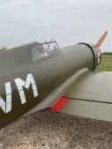
Vailly FW 190 1/4.5 (Nick Somerville)
Nick Somerville replied to Nick Somerville's topic in Scale Matters
Finally some decent flying shots taken today by our club Chairman Chris Montagu. Engine is starting to bed in nicely now. Swinging a 26 x 14 prop topping out at a little under 6300rpm in the air and 5000rpm on the ground. -
Used insulation foam to shape the wing pylons on my P47. Lovely to sand (outdoors). Faced the flat area with balsa and covered in a couple of layers of light glass/epoxy. Have proved very durable.

