


EarlyBird
-
Posts
3,613 -
Joined
-
Last visited
-
Days Won
5
Content Type
Profiles
Forums
Blogs
Gallery
Calendar
Downloads
Posts posted by EarlyBird
-
-
9 hours ago, leccyflyer said:
I've come to the conclusion that there probably isn't anything wrong with the transmitter in this case. It just isn't behaving how the OP expected it to. Despite the fact that more than one person has tried to help in finding out whether there is an issue, by a couple of very simple tests and questions, the OPs reluctance to provide an answer to those question is an indication that the TX is more than likely functioning as indicated in the manual.
As stated early on in the original thread it's probably for the best that the model is returned for a refund.
Totally agree with this. There is no reason that the manufacturer of a RTF has to make the TX conform to the expected mainstream conventions.
I am wondering what will happen if there is nothing wrong with it because it has been opened and been played with.
Steve
-
3 minutes ago, leccyflyer said:
Aye, in theory, but I did that just the other day and it certainly confused some people , who thought that the quoted post was by the thread starter, rather than the person who made the post😄
I thought it was odd that you didn't know. I remember that but you did it like this
which did confuse me at the time. 🤣
Steve
-
 1
1
-
-
20 minutes ago, leccyflyer said:
the ease of being able to quote replies in the thread, which is far from straightforward between threads on this platform.
Easy enough.
On 05/08/2023 at 13:17, Rich Griff said:After reading the recent article in rcme ( June issue ? ) Magazine, I took the plunge...
I would have liked the spitfire version ( the wife loves them ) but settled on the bf109 version, mode 1.
Anyone else got one of these ?
The "digital trim" on elevator does not bleep when given down trim command and only bleeps per " pull" one bleep at a time rather than "multi bleeps" when held in up command. No "central bleep" when system detects "central position" and no trim movement seen on elevator at all.
Throttle trim bleeps on up and down throttle trim but does not seem to effect maximum power or throttle off.
Anyone else having this problem ?
Replies appreciated before I contact supplier and Perkins...
Not flown yet as suspect a problem and it's far tooooooooooooo rough and wet here...
Thanks
Use the "+" not Quote and the quote will follow to another topic with a small pop up box. Having said that two topics on the same subject is confusing.
Steve
-
 1
1
-
-
This build is on hold while I complete Hound Dog which is now at the covering stage. I have included side thrust, as a test, which will be adjusted as required. The aim being to fly with no rudder trim required, just for fun. I do find it interesting that models can be set at 0/0 and the trims used to correct for side and vertical forces and yet others for example last years Mini Super has 2.5 Deg. side thrust built in. A subject for another topic I am thinking.
Still thinking about this build though. I will probably build 1 Deg. side thrust in and test fly then adjust and finally build the cowl. Having said that I could change my mind.🤣
Steve
-
I took my first steps into IC petrol recently and just followed the manual. Five years of listening to numerous experts convinced me to follow the procedures set out in the manual.
All engines need running in except Lasers. @Jon - Laser Enginessets them up just fit and fly, amazing, the only thing to do is not alter the settings.
Steve
-
JPerkins.com manuals
-
-
With all my five years experience of watching others glow engines dead stick and being told it's running too lean.
How far are you down the running in process as detailed in the manual?
Steve
-
-
33 minutes ago, Rich Griff said:
Just re read David Ashby rcme June article on this/these models....
Is David on here ?
🤣
-
25 minutes ago, PDB said:
Darker theme
As before the Darker theme has a navigation problem. Default theme works as normal.
-
1
-
-
1 hour ago, toto said:
Just considering any potential advantages to retaining accuracy as you progress the build. I'm thinking of the Kestrel here.
The Kestrel ribs are flat bottomed which is ideal for building over the plan. To me a wing jig would add complications with no benefit with regard to accuracy.
Steve
-
1
-
-
7 minutes ago, kc said:
Has anyone mentioned that side thrust means adjusting the engine mount so the cowl fits nicely? It's easier without side thrust or down thrust!
I have already included for 2 Deg. side thrust fortunately no glue has been applied so I can easily move the claw nuts. I do find the best way to learn is by making mistakes 🤣
-
2 hours ago, toto said:
I like the simplicity of the RCM jig and think it would be easy enough to make.
Is there a model that you require a wing jig for?
-
Thanks Graham, it looks like this is going to be a committee decision (compromise🤣). My thinking is that the motor causes torque and right thrust or rudder trim counteracts it. Similarly a high wing causes the nose to lift and down thrust or elevator trim counteracts it. It strikes me that Peter's designs need so little trim it makes thrust changes irrelevant.
Still thinking.
Steve
-
Not twisted but.
Servo extension leads and Y leads from 4-Max
I wonder if George will do a deal for multiples.
Steve
-
1 hour ago, Peter Miller said:
But of course with your vast experience you may know better!
That's just the point of asking, I have very little experience. It was a request from an instructor, my understanding was that he would prefer side and down thrust for beginners to fly straight and level hands of, something to do with building confidence. Why adding down and side thrust enables hands off straight and level flight is beyond me.
Interesting about Peggy Sue because he flies one and loves her. I will ask him again.
Thanks
Steve
-
As this model will be for a beginner I think that down thrust and side thrust will help. How much? I am thinking 2 Deg. down and 2.5 side. Any thoughts?
Steve
-
9 hours ago, toto said:
.. servo leads no where near long enough .... so .... out with these .....

When using keepers and the thick servo wire on larger servos I have had to enlarge the wire slot so that they can be pushed right on and click over the join.
Steve
-
-
I have two, Tiger Moth and Giant Stick. Both needed loads of lead in the nose, 450 gr and 900g respectively, and wing tip covering looking like they had been picked up by the wing tips in the factory.
The covering is poor, sticky backed plastic, it winkles in the sun and melts at the lowest temperature my iron will go down to. By what I have read it also fades quickly. Mr Vin Quin likes the printed sticky backed plastic so I would not expect it to change.
I will not buy another.
Steve
-
1
-
-
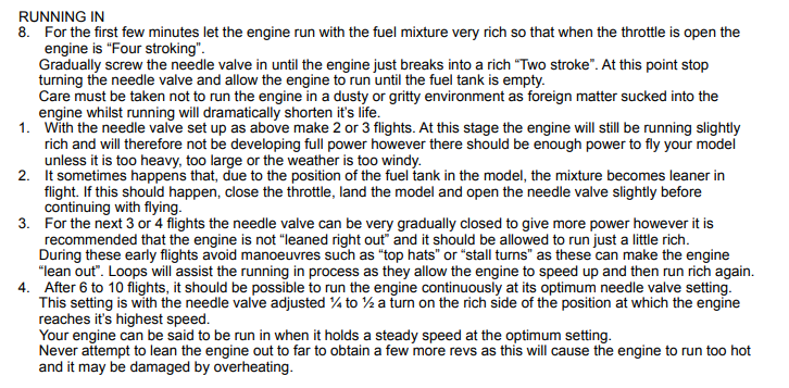
Engine mount fitted to F1
and test fitted to the fuselage
Having deliberated for a long time over how to mount the engine I found out that the bolt holes are in a square 45 mm apart. 🤣 No need to make a decision now. 🤣
Steve
-
1
-
-
38 minutes ago, KenC said:
Another shout out to electronics designers ... remember the days in the computer industry when sensible people would print a small triangular marker on the board just so you understood the pin settings.
The dots tell us where pin 1 is
Then count down that side to pin 10 and up the other side 11 to 20.
Steve
-
55 minutes ago, Mike Blandford said:
My guess is the 4 empty pads are used when programming the device.
I made a mistake I should have said pin 18 not 13. Pin 18 is indeed the SWIM pin for programming the MCU and as Mike said have not been used.
Could be anything then, the puzzle continues.


Peggy Sue 2
in The 2023 Forum Mass Build
Posted
I went flying this morning and used the last 5.25l of fuel in the FG21, only taken me four years. Hmm I thought I need to run the FG11 in which made me think of this build.
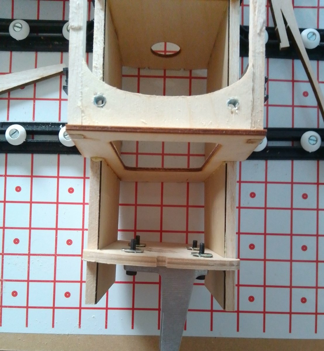
F1 now glued in
and UC side plates adjusted to make them offset.
Steve