Saint 1
-
Posts
60 -
Joined
-
Last visited
-
Days Won
2
Content Type
Profiles
Forums
Blogs
Gallery
Calendar
Downloads
Everything posted by Saint 1
-
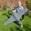
Well, after another week it’s finally just about finished! After spraying the blue I then masked off the fuz and wing to spray some white (I didn't spray them in the garage as it might look!) I used an assortment of masking tapes but found the Tamiya squared masking sheets particularly useful for creating the chequerboard pattern on the nose. It took me four hours to mask the fuz, not helped by me masking half of said chequerboard pattern before I realised I was masking off the white squares instead of the blue! With that done I then sprayed a couple of coats of clear gloss sealer over my ally nose spinner and exhausts to protect them from the elements and then went on to fit the exhausts. I was unable to find a good quality photo of this plane’s instrument panel so used the same one as I had previously in my standard sized Super Corsair. After having painted inside the cockpit I then added the instrument panel photo. Similarly with the engine, I also used the same Photo-shopped image as previously. I sealed both photos with a couple of coats of clear satin coat sealer to prevent them fading. I had already trial fitted all my radio gear and linkages prior to spraying so it didn’t take too long to re-install all these again so then all that was left was to get the CG point ‘right’ and weigh it. My standard build Super Corsair has its CG point set in line with the plan at 3.25” or 82.5mm from the root L.E. and it flew well right from its maiden. However this seemingly has a static margin value of 17% according to the rcplanes.online CG calculator so, on the face of it, pretty nose heavy. It weighs just 1437g giving a wing loading of 15oz/sq.ft. It will fly comfortably in wind speeds upwards of around 12mph and with considerable ballast has flown in up to 40mph winds. Based on all the above I decided to calculate my CG point for this 120% Super Corsair using the same 17% static margin which worked out to be 103mm from root L.E. Achieving this necessitated installing a further 150g of nose ballast inside the battery tube, over and above the 500g I had already built in earlier! So with the plane balanced it was time to hit the scales….a tad heavier than anticipated at 3232g or 7lb 2oz. This is giving it a wing loading of 24oz/sq.ft. for a plane with a 61.5” wingspan. Does this sound a lot or still ok for a PSS? What sort of wind speed do you guys think it might need for its maiden off the Orme please? There are still one or two little more bits of detail I may yet add but here are a few photos of the finished build and one or two with its little brother in the background, hope you like them! Nose spinner clear cowl fitted and retained by an O-ring Tail wheel painted My pilot could do with a little more detail, I'm sure he'd appreciate some sunglasses one day 🙂
-
Well my eagerness to make some more progress on my build finally got the better of me. It wasn't particularly warm yesterday (about 10 deg C) and a bit breezy but I decided to have a go at getting some paint on nonetheless. Thankfully it just about all went ok, one or two minor runs on the wing but hopefully I'll be able to minimise those with a bit of polishing in due course. The biggest challenge though was manipulating the wing and fuz whilst spraying them due to their size and in the case of the fuz the weight as well because I had already built in 500g of nose weight! I used aerosol spray paint, four cans worth so a bit more weight added there I should think 😄 I'll give the paint a few days to harden off and then I'll be able to think about masking off to spray the white graphics and get on with everything else too 🙂
-
Thanks Phil, I promise I'll build something in balsa over next Winter 🙂
-
Once I had finalised construction of the cockpit cut-out I used a bit more filler to close off any exposed flutes and then moved onto the canopy. For standard sized Correx builds it’s generally possible to create a canopy from one or sometimes two 2 litre pop bottles. For this scaled-up version that was not going to be possible but fortunately I managed to find some 3 litre lemonade bottles that were just about large enough. I made a few Correx templates for reference and then carved some previously glued together blocks of wood to shape. Once I thought I had the shape about right I then tried to mould a single 3 litre bottle over it, which failed miserably. Ultimately the bottle wasn’t long enough plus I was unable to shrink the ends down sufficiently before it overheated and turned white. For the second attempt I chose to make the canopy in two pieces with an overlap joint where the canopy frame would be and this proved to be far more successful. With the two halves glued together using canopy glue I then used a series of tiny self-tapping screws to secure it place. Having done all this, a few days later I then looked at it afresh and decided the rear section of the canopy was too bulbous so went on to modify my wooden block and mould a more teardrop shaped version in its place. This looked a little more representative of the real thing so I then went on to paint the frame. Finding photographic images of the cockpit detail of this particular aircraft remains a challenge since sadly both the plane and its pilot were lost in a crash in 2012. It seems many features of the cockpit area in particular were unique to this aircraft so I am having to use a bit of licence in guessing what some of those features actually looked like. The rear stays for the pilot seat aren’t too much of a problem so I’ve created those from some offcuts of carbon and aluminium. Detail of what’s happening behind the pilots seat is a little more sketchy though so I’ve created my interpretation of it using carbon rod, some plastic sheet, heatshrink, electrical wire, a nylon spacer and some tin. The only photo I’ve managed to find of the cockpit instruments themselves is this 360 degree panoramic one by Moose Peterson, plus there is some in-cockpit video footage too so I have yet to see what I can come up with in the way of a photographic image of the instruments at least… I am using a David Banks pilot figure – beautifully modelled by David and super lightweight too. He is only a bust figure so my cockpit is quite shallow in depth to suit. I’ve got him mostly painted now with just a little more detail to add. For the plane my plan is to spray paint the blue and the white chequerboard and stripes, then use white self-adhesive vinyl for the text and numbers but I am holding off from doing that until we have some warmer weather. So for the time being everything is now on hold. Roll on the warmer weather! Phil
-
The tail surfaces of my current Super Corsair have always been a little wobbly, partly down to their 3mm thickness but also the limited strength of the fuselage location so this is something I wanted to address here. To that end I have made all the tail surfaces from 2 layers of 3mm Correx with one or two 2.5mm carbon rods inserted too for good measure. They are just about visible in the second photo below. I then closed off all the exposed flutes in much the same way as the wing. I have used Evo-Stik to do this which generally seems to work well but I have found that at times when Evo-Stik gets inside the Correx flutes it can react and cause the Correx skins to ripple a little as can be seen at the top of the rudder. I don’t know a solution for this but a little filler applied subsequently can help to mask the effect. For the fuselage formers I have stuck with the traditional 2 thicknesses of 3mm Correx with the flutes at 90 degrees to one another except at the very front and the two formers which abut the wing leading and trailing edges where for strength I have used 3mm ply glued to a single piece of 3mm Correx. For the 3mm Correx fuselage skin I de-fluted every other flute to allow it to be formed whilst still maintaining a degree of strength. It won’t be immediately obvious in the subsequent build photos but wherever possible I have also applied heavy duty clear tape to the inside of the fuselage skins in attempt to reinstate some of the strength sacrificed in the de-fluting process. As with the majority of my builds I also incorporated a square Correx battery tube through the foremost formers to enable fine tuning of the CG by positioning the 4 cell square NiMH battery pack within it. Generally Correx fuselages are built up using a wooden dowel to locate the formers and help maintain a straight fuselage but I have not used one on this build. The foremost formers are located on the square battery tube anyway and with care it is possible to add the remainder accurately. Once the top half of the fuselage skin forward of the wing had been glued to the formers I moved to the tail, gluing the two undersides together followed by the former immediately rear of the wing, taking care to ensure it was positioned correctly to match the wing chord dimension at that point. Having already glued the tailplane and fin together I was then able to glue the tail assembly into the fuselage. I temporarily inserted a carbon rod into one of the formers to act as a vertical reference and so ensuring everything was nice and square. From a previous similar Corsair build on the RCgroups.com forum I reckoned I’d be needing around 500g of ballast in the nose so I secured the requisite amount of wheel balance weights in place using hot glue and glass fibre tape prior to fully closing off the forward fuselage skin. Hopefully any fine adjustment of the CG should subsequently be possible by repositioning the battery within its location tube without the need for any additional ballast. I then introduced the remaining formers and started thinking about the required cut-out for the cockpit. With the forward fuselage skin fully closed I was then able to taper the nose down at the front and start roughing out the cut-out for the wing. Before final fitting of the wing though I always hot glue a supporting layer of 3mm Correx on the inside edges of the fuselage skin with the flutes aligned 90 degrees to those of the fuselage. This not only adds strength but also makes final trimming of the fuselage sides much more precise; it is far easier and more controllable to carve across the flute channels with a scalpel rather than along them as would be the case with the fuselage skins alone. Once the tapered nose sections were glued in place I cut away the excess flush with the ply former and then turned up a fairing piece from ply using a lathe (Well not really, please don’t try this at home! 😀). With the fairing piece glued in place there would then just be a little filler required to smooth things out. Using my ‘lathe’ once more I also managed to turn up a piece of aluminium bar to make the nose spinner, I will ultimately polish this up and then lacquer it to protect it from the salty Orme air. With the nose spinner made I then used the top section of a 3 litre pop bottle to make a clear fairing cover for the engine in order to minimise drag from the otherwise flat front end. I will use a suitably sized o-ring on the ally nose spinner to help hold the fairing in place. To further strengthen the tail surfaces, on this build I have introduced an additional former immediately in front of the tailplane leading edge, along with some carbon rod cross-braces hot-glued into the rearmost compartment. At this point I also installed the carbon control rods for each elevator along with the snake for the rudder. The snake was required so as to pass underneath the cockpit rather than through it. This particular Super Corsair had no fewer than 14 exhausts (for its 4 bank 28 cylinder radial engine) four on either side of the fuselage and six on the underside. I cut the fuselage sides accordingly and introduced some thin ply pieces to create the outlet ducts on either side. The underside of the wing required a fairing piece to blend in with the fuselage so I used a few pieces of ply and Correx in order to achieve this and at the same time glued in a ply support pad for the wing bolt fastenings, followed off by a little more filler. With this done I was then just about able to drill six more holes to locate the remaining six exhausts, all of which I am making from aluminium tube. I glued in a ply radio tray as far forward as possible, thus keeping all the radio gear forward of the CG point. (With any PSS build of a piston-engine plane it is always imperative to keep weight as far forward as possible in order to keep the amount of subsequent nose ballast to a minimum). The wing leading edge air intakes are something of a defining feature of the Corsairs and something not at all easy to recreate on the thin folded leading edge of a Correx wing but I have made an attempt here with the addition of some balsa scoops glued on either side. Once painted up they will hopefully recreate the look to some extent at least. There is a pitot tube on the leading edge of the port wingtip so I have managed to recreate this using the inner from a control rod snake glued into a piece of brass tube with a little brass shark fin soldered to it. The whole thing is removable and is a nice snug fit into a disused biro tube that I have glued into the wingtip leading edge. Hopefully its flexibility will mean it shouldn’t get damaged on landing. As with my original Super Corsair I once again fabricated a Correx air scoop for the top of the fuselage but this time chose to blend it out all the way back to the canopy – more filler required here too. For a bit of extra detail this time I turned up a ply tailwheel, cut it in half and glued and pinned it through the fuselage into a fuselage former. It feels secure so I hopefully won’t knock it off on landing.
-
I’m more than a bit late to this party I know but I discovered this Correx build thread the other day and seeing as I can’t seem to stop building in Correx myself I thought I’d post up some photos of my previous builds along with the one I’m on with currently (build number 16!) I started off in early 2019, like many by building the much tried and tested Mig, followed by the A10, Reno Racer Super Corsair, Red Arrows Hawk and then another Mig to replace my first one which suffered one too many heavy ‘landings’. I then went on to modify some balsa plans to make a Mosquito followed by three L39s (part of a group of six in total), a Silver Falcons Pilatus PC-7, a pair of Hawks in the 2010 colour scheme, the Rolls-Royce Spitfire and then most recently 2 more Hawks for a fellow flier. Of all the builds it has been my Red Arrows Hawk and the Super Corsair that have seen most action, some of you may well have seen them and indeed some of the others at the Orme over the last couple of years. I’ve always loved the look of my Super Corsair and it was one that flew well right from its maiden. It’s had a few bumps and scrapes since and there are a few improvements I wanted to make too so I decided this Winter was the time to build myself a new one, still in the same Reno Racer colour scheme of aircraft NX5577N but BIGGER and hopefully better. Initially my intention had been to build something more scale in balsa this Winter but I’m still relatively new to rc flying so I thought I’d give it another year before doing that and hopefully allow my flying skills to improve a bit more in the meantime. My new Super Corsair will be a 120% version of my current one, making it close to 1/8 scale with a clipped wingspan of 62”. At this size it is just possible to cut the wings and fuselage from 4’x2’ Correx sheets. Finished weight is going to be in the region of 3kg (with around 500g of that being nose ballast). For strength the wings will be made from 3mm Correx rather than the usual 2mm. The ailerons are double thickness rather than the usual single piece of 3mm Correx, both for strength and to blend more smoothly with the wing. I’m introducing a rudder in addition to the standard aileron/elevator set-up. All exposed flutes will be sealed with either balsa, 1mm ply or filler to improve the look and hopefully performance too. The wing will be secured with wing bolts rather than rubber bands. All the tail surfaces will be made from two thicknesses of 3mm Correx rather than one and additional bracing and formers will be introduced to increase rigidity of the tail – a weak point of my current Super Corsair as one or two noted on its last flight from the South slope of the Orme, admittedly when the wind speed was well over 40mph! I’ll add as much extra scale (ish) detail as I’m able along the way. This isn’t a full photographic record of a Correx build since much of that has been covered many times already so I’ll concentrate on the things I’ve chosen to do a little differently, for better or worse! Firstly though, some notes on sourcing Correx. Like everything it seems to be getting more and more expensive and tricky to source. Ideally you want to find somewhere local to you where you can pick it up directly because delivery can be both tricky and expensive. If you can get hold of 8’x4’ sheets then that allows you more scope to build bigger but generally 4’x2’ or 4’x3’ sheets work well provided the flute direction runs along the 4’ length, plus they should hopefully then also fit in your car. If you’re having it delivered then make sure it will be delivered flat as many places will either roll or fold it rendering it useless, particularly so with the thinner 2mm sheets. Standard Correx builds generally use 2mm thickness for the wings and then 3mm for everything else. Some time ago I also sourced some non-Correx brand 2.5mm thickness sheet which I have used on many of my wings in lieu of the 2mm and will be using again on this build for my ailerons. The suppliers I have used most recently are:- 2mm Correx:- Kite Packaging 2.5mm Non-Correx brand sheet:- The Plastic Shop 3mm Correx:- K&M Wholesale Suppliers And so to the build itself:- Due to the number of photos I'll spread this over a few separate posts... For greater strength I opted to make the wing from 3mm Correx rather than 2mm. Standard practice is for the aileron to be produced from a single piece of 3mm Correx as well with one flute cut away to make the hinge. This results in a step between the aileron and both the upper and lower surfaces of the wing as per the diagram below. Over time I have also found the aileron is prone to distorting so for my build I have chosen to effectively cut most of the 3mm aileron away leaving just a stub which I have then sandwiched between a folded length of 2.5mm sheet forming a new and more robust aileron. This aileron then transitions more smoothly from the upper and lower wing surfaces. In theory 3mm Correx should have provided a fully flush transition between the wing and aileron surfaces but I opted to use 2.5mm instead, favouring a slight waterfall effect rather than running the potential risk of an into wind step. I glued a few balsa webs within the aileron for support, one of which also serves to strengthen the control horn mounting area. Once folded, I closed the exposed ends off with 1mm ply or balsa as felt appropriate. The wing spar is made from 9mm ply pinned and glued at the crank points and I have then glued and screwed a block of wood in place to support the front wing mounting tab. I allowed for a spacer under the mounting tab in order to provide some adjustment on final assembly with the fuselage. Ply servo mounts were glued to the spar and wing lower surface followed by a bead of hot glue for extra security before fitting the servos. The four sections of upper wing were folded in the normal manner. The exposed flutes on the wing tip leading edges were then cut away and some balsa strip introduced and sanded to shape, followed by some 3mm ply for the wing tip itself and 1mm ply for the trailing edge part. A balsa strip was also introduced to close off the exposed flutes of the wing upper surface along the aileron hinge line as shown in the last photo above. With the wing nearing completion I felt a photo comparison with the standard wing was in order. Although it IS only 20% bigger it somehow looks more like 50% in the photo! Note that I also chose to reduce the aileron length this time in order to make them look a little more scale in appearance. No flaps though – they looked like being way too complicated! I closed the rest of the wing trailing edge flutes off with 1mm ply, I’m not expecting any aerodynamic gains here but to my eyes it will at least look better. And then to tidy things up I then glued a couple more pieces of Correx over the previously open upper surfaces of the wing, leaving a small slot for the servo wires to exit from. Continued in next post...
-
Well I had a great time flying my Alpha Jet at the Orme last weekend with PSSA online but I had to move my CG point back some way before I had it flying nicely. I had to dispense with the two nails and move my lipo back by 20mm to end up with CG being 85mm from the leading edge. As a bonus the AUW is now down to 115g. Can't wait for next time 🙂
-
Great shots Steve, I know we didn't make it easy for you with our little AJs 😄
-
No I don't think so Rich. The one I have just built was advertised as 600mm which must refer to the overall length, the wingspan is 467mm.
-
Now, I know I’m more than a little late to this party but having seen Harry’s Alpha Jet in action on the Orme I fancied building one for myself. Having read through the build logs on here and with much guidance from Phil and Harry along the way I now finally have one ready to fly. I won’t go through my entire build as it’s obviously very similar to what’s gone before but here are a few photos anyway… The weight of the original glider was 72g. I used flat carbon strip where I could and rod where space was at a premium. I used 190 micron mylar hinge for the elevators and ailerons but found the width as shown in this photo was way too much, making the hinges too stiff so I subsequently cut them down to something in the region of 4mm wide. I used a carbon rod to locate the front of the canopy and magnets for the rear. I found the elevator linkage hoop required a good width to ensure the two brass levers didn’t foul at their full extent of travel. (The gap between the two brass levers varies through their travel due to the effect of introducing anhedral to the tailplane). AUW with all the radio gear but prior to any paint was now 97g. I sprayed the plane initially with a clear plastic primer, followed by a few thin coats of white acrylic primer before applying Tamiya matt white acrylic which then brought the weight up to 101g. Now I was ready for some colour and of course I needed to find a different colour scheme to what’s gone before. As seems to be my way of late I ended up choosing something difficult! The Portuguese Air Force ASAS colours. I lightly sketched the shapes onto the primed surface using a soft 6B pencil until the proportions all looked about right and then masked up, spraying red first, followed by the green and then black. I used Tamiya matt acrylics and my new spray gun and compressor (Thanks for the recommendation Harry). There was much touching up of paintwork along the way, partly due to a little paint lift and bleeding under the tape in places but also due to the translucency of the white and red colours in particular. I also found the matt white finish difficult to keep clean during the whole process. Another first for me was making my own waterslide decals although this did require much assistance from our daughter in the Photoshop department. I have to say they went remarkably well and I’m particularly pleased with the chequerboard finish around the nose, something I had previously thought I would have to do by hand using either paint or a Sharpie. Once the decals had dried I then gave everything a couple of light coats of clear satin sealer which should hopefully give it a little more durability against any knocks or scrapes, time will tell. Weight at this point now 114g Prior to any paint I thought I had the C of G something close to the 78mm from L.E. figure but subsequently found I needed to add a couple of small masonry nails up front to bring it right meaning my AUW finally is 118g. Not the lightest but not too shabby given the amount of paint! In hindsight maybe I should have tried to install the elevator servo further forwards as Harry did with his and thus negate the need for the nails. All I need to do now is get out and fly it, I hope to be able to maiden it in the coming week or two in readiness for the next PSSA event on the Orme. Phil 🙂