

Simon Chaddock
-
Posts
10,644 -
Joined
-
Last visited
-
Days Won
18
Content Type
Profiles
Forums
Blogs
Gallery
Calendar
Downloads
Posts posted by Simon Chaddock
-
-
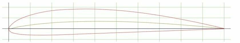
An under cambered section will create more lift so it will be able to fly a bit slower but if stalled the effect is likely to be bit more severe with a pronounced nose drop. Any small variation between the wings will mean a severe wing drop and the beginnings of a spin.
How severe these tendencies might be will depend on the wing section and the degree of under camber.
Some WW1 types with a thin section and under camber were deemed to be unrecoverable from a spin although the relatively sharp leading edge was probably the biggest cause. When Fokker introduced thick wing sections but that still had slight under camber the propensity to spin after a stall was virtually eliminated.
A typical WW1 wing section.

Fokker Triplane wing section.
There is little wrong with the good old Clark Y section which is flat bottomed over the majority of its underside so can be built on a flat board..
I hope this helps.
-
Is it a wheel?
-
My humble 4 button IMAx certainly starts of a balance charge with the set charge rate. It gradually drops the charge rate and starts "balancing" (it appears to cycle around the cells) when at about 4V per cell. I too always balance charge.
As towards the end of a balance charge the charger is using the balance plug to measure tiny voltage differences any slight contact resistance variation in the plug contacts can upset the end of the balance charge. Sometimes just a "jiggle" of the balance plug can result in a really slow balance charge suddenly being completed. 😄
-
Jonathan
Changing the pins on a balance lead plug is tricky. Nothing like as simple as a servo plug.😒
I have solder equipment so my solution is fit a complete new plug and solder the old and new wires together covering the joints with shrink wrap.
Do be careful you do not dislodge any wire from the LiPo itself. The cell tags are aluminium so unless there is some ordinary solder still visible you wont be able to solder anything back on..
-
 1
1
-
-
Really very nice.
About the only comment I could make is with the diagonal wing bracing strut. As you have them positioned under load they will put a bending force on to the vertical struts.
Note on the full size the diagonal strut goes all the way to end of the vertical struts so no bending moment is created.
I am sure it will be fine. Just a "picky" observation.
The fuselage struts follow the full size so are no problem.
-
Nice idea but a structure capable of withstanding the forces as the foam expands would be very heavy indeed.
-
I am sure it will be adequately strong but it does look look quite a bit of extra wood is going in to make that fuselage/wing joint.
-
The fact that 3D printing is done in individual layers of an extruded filament means the final structure is many times stronger along the line of the filament than across it
For practical quality printing a wing is normally printed vertically growing out of the bed. done like this means the wing is far weaker to bending forces than if it could be printed with the filaments running span wise.T
he normal solution to this problem is to arrange for a suitable cavity to be left in the wing to allow a carbon "spar" to be inserted.
It works but it does rater ignore the underlying strength of the printed material.
If the wing is divided into fore and aft sections it can then be printed with a span wise filament direction.
As it is printed as a homogeneous structure it does favour it being a "D" box structure with no spar required.
The front part can be printed with a thicker skin for stiffness and strength. The rear part is really just for aerodynamics and can be printed a light as possible.
A test piece of wing printed in LW-PLA. The "D" box has a double wall skin the rear is single skin wall all over.
It has a span of 200mm and a chord of 137mm. It has a true Clark Y section and weighs 20g.
For its weight it is remarkably stiff in both bending and torsion.
The next issue is to see how to join several sections could be joined to create a reasonable span wing.
As all its strength is derived from the "D" box it is essential that the skin joint is such that the glue can transmit all the forces right up to that of skin failure.
So far I have developed a printed "plug and socket" arrangement for the D box that provides a sufficient glue area lap joint.
The D box plug end.
The D box socket end.
Two sections joined together.
As the rear section carries virtually no load these sections can be simply butt glue jointed
These are all "test" sections. With a standard bed printer it is just just possible to print a 270mm long wing section.
Five such would give a span of 1350mm but it would take about 35 hours of printing time!
So far my CAD skills limit this technique to a simple plank wing.
We shall see.
-
3
-
-
shepeiro
Looks good but I am a bit concerned by the top and bottom spars at the wing centre join.
The spars will actually provide virtually all the stiffness at the centre of the wing.
How will they to be joined? I presume the fuselage will provide some sort of joining structure.
If weight is an issue the lightest structure is a one piece wing with the spars joined so they act as if they were continuous. This will give the maximum possible strength at the point of maximum bending.
The fuselage can then be simply glued on top of the wing as the fuselage to wing joint is relatively very lightly loaded.
Just saying.
-
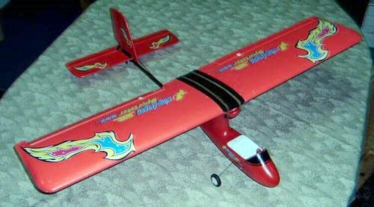
This will be the last of my "crashed & repaired" pictures until I crash something again!
To this. It flew very well indeed
Unusual and not intended to represent anything in particular as it was a rebuild from parts of this.
Which I had simply got tired of repairing!
-
1
-
-
A sub 250g light weight for me today. The weather was not ideal. Fairly light wind but pretty gusty and with many trees on the perimeter made it far from ideal for a light weight. All 2 & 3mm Depron apart from the fishing rod tail boom. Its one of my few 35 meg planes.
.
More of a glider than a power plane but with an 850mAh 3s on board it weighs just 219g. Quite exciting at full power with over 300g of thrust.
Sorry. Not a video of todays flight but it does show the trees around the site.
https://www.youtube.com/watch?v=-8sYWG-agnU
-
2
-
-
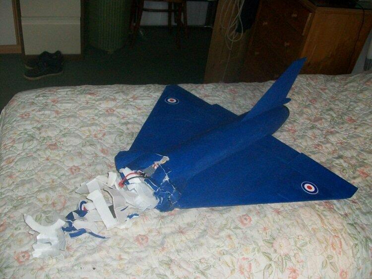
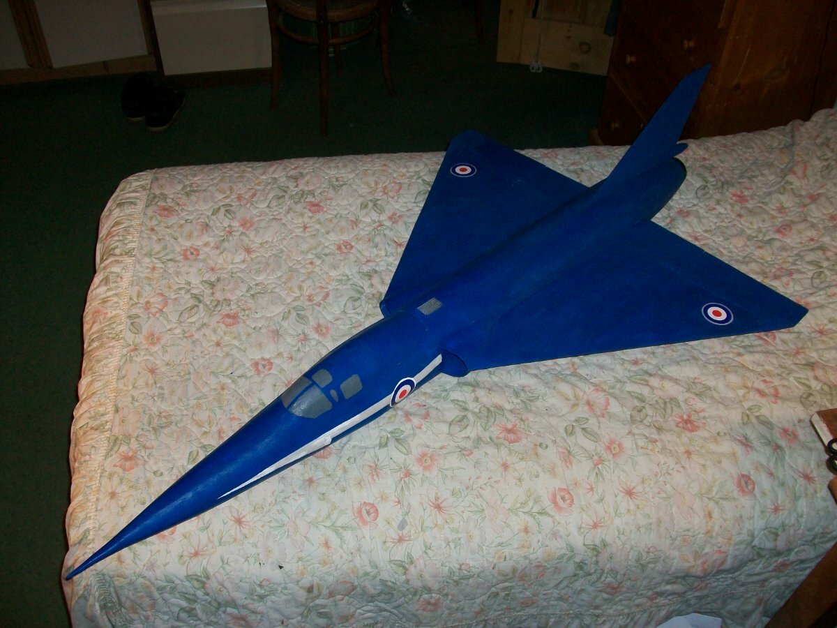
Its not that I crash a lot but I do like to record everything. Just to show the method of construction does save the rest of the structure another "nose plant". This time with the very light EDF Folland Gnat. It is almost entirely made of 2mm Depron
It required a completely new "stand alone" nose to be built and then grafted on to the undamaged rest of the airframe.
To get back to exactly how it was.
One advantage is the repaired structure is identical in construction to the original so the only "new" weight is just the glue used to fix it on.
As before all the electrics were undamaged and the battery reused.
-
3
-
-
The way I build using a foam stressed skin crumples progressively so whilst any damage is severe the rest of the airframe is completely undamaged.
From this "nose plant"
Via this
Back to this
ESC, EDF, Rx and servos were untouched even the battery was completely undamaged & reused.
-
5
-
-
This was probably my most disappointing crash.
A wing tip simply unplugged in flight!
I did repair it and it has flown again a few times.
I do have some more.
-
4
-
-
At 18" span my wing would weight 12.9 x 18/22 x 18/22 which comes out to 8.7g.
I think when yours is complete, covered and painted it will have gown a bit in weight particularly when the reinforcement for the motor housings is added.
A feature mine would not need as I am sure it is rigid enough that the motor housings could to be simply glued directly onto the wing surface.
I don't think I will be building any more of it as I don't have the light weight servos, ESC or receiver.
-
shepeiro
I am impressed by you building skills
1.58g? That seems very light for all that balsa.
I assume any area not sheeted will be tissue(?) covered. It is the all over covering that provides virtually all the torsional stiffness in a convention "rib and spar" wing.
You may recognise this wing plan form! 😉
Just for fun I made a few days ago out of 3mm sheet foam. No ribs, the foam skin is just formed over a single foam "spar" to create a wing section.
With a span of 22" I think it is a touch bigger than your wing. It weighs 12.9g painted.
It is fairly flexible but can carry a 70g centre weight and with its all over skin it is relatively rigid in torsion.
I do worry about the amount of lift generated by the narrow chord of the outer half of the wing.
-
 1
1
-
-
My guess is the stick was originally a tight push fit. This put the gimble socket under tension which over time caused it to split. Moulded plastic under tension is not a good idea. If you do use cyano glue the stick in at the same time. The stick itself will add to the glue area. holding the gimble together.
-
Adsjking
If you want to fly the modern day equivalent of what I started out with I would suggest something like this.
Not cheap but at 1,4m span sufficiently large to respond slowly enough to give you time to think. it will certainly fly. All you have to do is assemble it. Kings Lymm Models are a reputable model shop. You have to consider such a purchase as an investment to get you started.
It is "plug and play" which means it is complete but you will need a transmitter, a receiver and a battery. It can be argued you will need such anyway for when you want to fly your own build.
Moulded in EPPO foam It will be a good bit more robust than any balsa stick model.
Be wary of similar from Chinese suppliers. They may look a good bargain but there are many pitfalls from suppliers so far away.
I hope this helps.
-
Given the super clam conditions today I flew two planes.
The flapped FX707 again with some adjustments.
Had an interesting fault. The grass was frosty. After I landed for the second time the motor refused to run. Quite a bit of wet grass bits were on the underside including a couple of bits on the external ESC mounted on the side of the fuselage. One was actually touching the connections of a MOSFET. Blew the grass away and the motor worked!
Memo to self - don't fly this plane on wet grass.
Next to fly was an oldy. The "Endurance" which was built in 2015!
As a "floater" specifically designed to fly using the minimum power (about 10W continuous!) it only works well in near calm conditions. Flew for 20 minutes yet its fully charged battery was still showing 4.18V in each cell.
A plane a bit wasted on even a 20 minute flight but it is a relaxed form of flying!
-
Adsjking
Learning to fly is different to understanding how to set up an RC plane so it will fly well enough for you to learn on. Unless your plane can fly properly the danger is you will get much better at repairing it than learning to fly it.
I was an experienced model builder when I decided to take up RC flying seriously. Like you I had little idea of what the current RC equipment was and had never flown RC but like you had build and flown many small rubber power planes and gliders as a lad.
I hunted round and decided to buy a "Ready to Fly" RC plane sold as as trainer. It was absolutely complete and even included the transmitters and all required batteries. It was made of plastic and foam. Simple and fairly robust. Note it is a pusher so the prop was less likely to get broken in an "untidy" landing.
This meant I knew the plane would fly, the only question was could I learn to control it before I wrecked it. A real possibility as I am a self taught lone flyer with access to a not very smooth grass field.
Sure enough it did fly well enough from day 1 and once I was confident I could expect to repeatedly fly and land it successfully I moved on first modifying it and then building my own designs which I knew I could do now I had a basic understanding of the RC equipment required.
Over many years I have designed, built and flown a wide range of planes.
Just a brief description of how I started. I hope it helps.
-
3
-
-
Flew both XF707 Albatross chuck glider RC conversions today (28th) but only after the serious fog had lifted by noon!
Although blue sky as the sun dropped lower it made the haze thicker which made planes hard to see at any altitude so flying was terminated before I the risk of loosing one got too great..
They fly and with folding props glide really well.
Their only quirk is that neither ESC has a brake option so to get the props to fold you have to cut the power and pull up into a near vertical stall to get them to stop wind milling and fold. They then stay folded until power is reapplied.
Both have a power on endurance approaching 1/2 hour.
Just need some warm weather and thermals.😉
-
3
-
-
Rich
Very nice.
Scale(ish) live steam "O" gauge but unfortunately not RC. It would be difficult as it is actually coal fired!
X
Intended to run on non scale track so over size wheel flanges. Note the Hornby couplings. All axles are sprung.
Scratch built by my Dad over 65 years ago.
We visited the FR in the late 1950s when they had just started running but only across the Cob . The deserted Boston Lodge workshop was incredible with everything just left lying as it was when it closed down.
-
1
-
-
shepiro
Bigger props will likely draw more amps unless they also have a finer pitch. That might actually reduce the thrust.
More amps will put the electronics at risk. To keep costs down it is unlikely the manufacturer would have built in a big reserve margin. Blow the electronic and its scrap!
-
Very nice. An interesting subject.
-
1
-


 X
X
Rescuing over-discharged LiPo?
in Gadgets and Electronics
Posted
Jolly Roger
The question with a slightly over discharged LiPo is not that it wont recover the nominal voltage but how much of the cell's chemistry has been damaged?
Such damage usually takes the form of a reduced capacity.
The damage issue becomes more severe if one cell has been effected more than the others. If the LiPo is then used that weak cell will reach a "damage" discharge level before the others and thus likely to be damaged further. There is the real possibility of a LiPo fire if the discharge of the weak cell(s) is taken too far.
The usable capacity of a LiPo must be considered that of its weakest cell.
With a damaged LiPo the problem is knowing what the reduced capacity is and acting accordingly.
With LiPo it pays to keep flight durations conservative.