Dad_flyer Posted August 13, 2019 Author Share Posted August 13, 2019 Now the airframe is in one piece I can check the CG properly... And... It needs nose lead . At least there is space in the front cowl, so nice as far forward, and all up weight (with battery) is still short of the 24oz design weight. Quote Link to comment Share on other sites More sharing options...
Dad_flyer Posted August 18, 2019 Author Share Posted August 18, 2019 Come to refitting the rods and control horns, but the horns are too long and hit the sides of the fuselage. Had to look back in my own thread to see that I have moved the servos and intended to shorten the horns, but I never actually did it! Quote Link to comment Share on other sites More sharing options...
Dad_flyer Posted August 18, 2019 Author Share Posted August 18, 2019 Tail surfaces joined with cut down fluffy mylar hinges as detailed on the plan. Glued with cyano down the pin holes. I may pin as well, as the holes are there. Putting the ball link on the inside of both rudder and elevator horns makes the rod line up, but it is a bit tricky to push the cup onto the ball... This is once I had worked out how to get the rods back in with the wings on. The z-bends mean they have to come through the tubes from the servo end. It worked by passing them back from the servo hole to the cowl through the battery hole, then they can thread back into the tubes. Quote Link to comment Share on other sites More sharing options...
Dad_flyer Posted August 18, 2019 Author Share Posted August 18, 2019 Servos linked up. This close hole on the horns gives the throws of 12-15mm as required. I have put a little ply tab over the hatch hinge position, just in case. Receiver will go up against the rear former in here. Hatch closed. Now I am just putting off bending the landing gear wire. Quote Link to comment Share on other sites More sharing options...
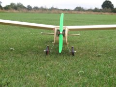
Dad_flyer Posted August 19, 2019 Author Share Posted August 19, 2019 The wire bending was not too traumatic actually. That is one of those illusions that sometimes I see inside out. Quote Link to comment Share on other sites More sharing options...
dan h Posted August 19, 2019 Share Posted August 19, 2019 Looking good df. I take it the axle is soldered to that frame? Maiden cant be far off now. Quote Link to comment Share on other sites More sharing options...
Dad_flyer Posted August 19, 2019 Author Share Posted August 19, 2019 Yes, the axle is soldered across the bottom of the frame. I am making up the saddle clamps, so that I can clamp the wire square and true to a board before soldering. All being well it will then hold in the right shape. Quote Link to comment Share on other sites More sharing options...
Dad_flyer Posted September 23, 2019 Author Share Posted September 23, 2019 It is a month since that last post, I still have not got the soldering iron out, or for that matter the receiver plugged in. Went to the Shuttleworth collection yesterday, which was an excellent day out. Child_nonflyer wants his done in the markings of their SE5a, so we have lots of photos... It is this one that has the underside cream at the tail. I had seen the cream underside in photographs of some examples, but of course in photographs of the underside you usually cannot see the other markings to tell which one it is. I painted it in cream first, as that would be easier to change to dark if necessary. It turns out the cream one is the one I needed. Quote Link to comment Share on other sites More sharing options...
Dad_flyer Posted September 29, 2019 Author Share Posted September 29, 2019 Bad weather this weekend, so no flying. Pasted part of the plan to a board to give some parallel lines with a good centre line. Screwed down the clamps and the wire frame. I could not get saddle clamps for 16SWG, so these are flat ones filed out. Fettled the fit by filing the bamboo skewer, then tacked the skewer with super glue. Filed the wire clean and roughed bound with fuse wire. And soldered. Seems all solid. Now to remove the skewer and find where I put the 14SWG for the axle. Quote Link to comment Share on other sites More sharing options...
Dad_flyer Posted September 29, 2019 Author Share Posted September 29, 2019 Axle found, cut, bound. I think it will need a washer between the frame and the wheel bushes. Quote Link to comment Share on other sites More sharing options...
Dad_flyer Posted October 26, 2019 Author Share Posted October 26, 2019 Wheels next. I did not have 1/4" liteply, so these are 1/4" liteply and two 1/8" balsa faces. I got to use my new cutter... Sealed with dope and then black tissue doped on for the tyres. The covers are cut from a yoghurt pot. I made four of the cones before I looked at my photos from the Shuttleworth collection to get the colour. The insides are flat, the outsides are shaped. Quote Link to comment Share on other sites More sharing options...
Dad_flyer Posted October 26, 2019 Author Share Posted October 26, 2019 All fitted and pretty much ready to fly now. 640g or 22.6oz with 3s 2200. It is a bit tighter than I had hoped to get the battery in and out. The CG is a little back from design, so that may make it over the 24oz design weight in the end. Runs this wooden 9x5 at 8300rpm and 130W, or a plastic 9x6 at 7400 and 160W. Maiden when we get a good day, then finish the markings and pilot. Quote Link to comment Share on other sites More sharing options...
Dad_flyer Posted November 17, 2019 Author Share Posted November 17, 2019 Got a few flights in yesterday on other models, then had enough time today to be at the patch long enough to get some air under the wings of the SE5a. Barely a breath of wind. Child_nonflyer insisted that it is not a maiden, and no photos are allowed until the markings and pilot are all done. I needed a flight to check trim, wing straightness and CG in case surgery was required. TN suggests that it is much best to hand launch this model as it likes to nose over. Consensus at the club was if it starts 6 feet up then down is an available direction of travel on launch. Having persuaded an intrepid test pilot, and found short-ish grass, it was a very short run and up into the air. Quite flighty until throttled back to a reasonable speed, then was beautiful to watch, and apparently nice to fly as well. A few clicks of rudder trim, then a lovely approach and landing. Where immediately it flipped onto its back. That is what TN says they are prone to do in the build notes, and the patch is soft and the grass a little long. Being small and light there is no visible effect from the flip. Even the wooden prop survived unscathed. Then the test pilot says it was his first biplane... So now no excuse not to complete the markings. Quote Link to comment Share on other sites More sharing options...
Dad_flyer Posted November 17, 2019 Author Share Posted November 17, 2019 I did not note before, about 1oz lead needed at the front. A double thickness of roofing sheet, curved to fit the inside of the top front of the cowl. The battery has far more capacity than the model needs, but it would only be replaced by more nose weight if I used a smaller one. Quote Link to comment Share on other sites More sharing options...
Dad_flyer Posted December 30, 2019 Author Share Posted December 30, 2019 Santa came with Tamiya masking sheet, so no more excuses on the markings. Child_nonflyer specifies the Shuttleworth example as the prototype. Being stingy I tried to get two roundels out of one sheet. This is not a good idea as the film is too flimsy to hold shape well once the backing is taken off when the boarder is so narrow. However I did get them lined up on the wings and base white is on. The bits left over from the roundel sheets gave plenty of space to be more sensible with the mask for the lettering. Using the stab and deck line to position it correctly. Child_nonflyer forbade stickers, so I am learning a lot of new techniques. The moment of truth on the lettering is near as the last coat is getting dry. Quote Link to comment Share on other sites More sharing options...
Dad_flyer Posted December 31, 2019 Author Share Posted December 31, 2019 The lettering came out well. Roundels masked for the colours. The masking came off pretty well, but needs a little touching up where it has pulled the paint in places. Quote Link to comment Share on other sites More sharing options...
Dad_flyer Posted December 31, 2019 Author Share Posted December 31, 2019 Quote Link to comment Share on other sites More sharing options...
Toni Reynaud Posted January 1, 2020 Share Posted January 1, 2020 Just found this thread. Looks really good, and I'm glad it flies OK. Well done. Quote Link to comment Share on other sites More sharing options...
Dad_flyer Posted January 1, 2020 Author Share Posted January 1, 2020 Thank you Toni. All being well it will still fly well with the extra weight of scale details that Child_nonflyer and Child_flyer are specifying... Quote Link to comment Share on other sites More sharing options...
Dad_flyer Posted January 5, 2020 Author Share Posted January 5, 2020 Getting to the really little bits now. The carriage for the gun first. Then the exhausts. I wanted to do a little more scale than the 9mm half round that TN has on the plan. Bamboo barbecue skewers are about the right size, and almost as easy to fit. The problem is that they run from the cowl to the cockpit, but the cowl needs to be removable. Not least to add lead to balance the pilot. I made a sleeve with chocolate penny foil. This is quite thick, and glued with cyano it holds its shape well. Not the best photo. The extra thickness is not too noticeable when painted. Then eight small exhaust stubs shaped and fitted. Well, if I started with the 'sad' option in the plan of doing the radiator louvres individually, I might as well follow it through. The joiner is pretty well hidden. Lots of little bits of painting as well, I have used nine different pots of paint and 5 different brushes so far. Edited By Dad_flyer on 05/01/2020 22:02:13 Quote Link to comment Share on other sites More sharing options...
Dad_flyer Posted January 7, 2020 Author Share Posted January 7, 2020 Further excessive detail. The little exhaust slots. And a wire bracket made to fit, with some totally unnecessary rust weathering. I thought it was going to be all finished when the exhausts are glued on, but Child_flyer reminded me about the windscreen . Quote Link to comment Share on other sites More sharing options...
Dad_flyer Posted January 7, 2020 Author Share Posted January 7, 2020 Exhausts and gun rail glued on. Windscreen made and glued. I think that is it finished . Just over a year in total , there were some long gaps in building when sorting out other models or flying. I shall do some better photos in daylight. Will any of this stay on in flight? Or more likely in landing? Edited By Dad_flyer on 07/01/2020 23:12:01 Edited By Dad_flyer on 07/01/2020 23:13:10 Quote Link to comment Share on other sites More sharing options...
Dad_flyer Posted January 8, 2020 Author Share Posted January 8, 2020 Daytime does not make the light much better at this time of year, but here are pictures of the completed model. Final discussions with the ground crew: (That is reflection, not a big smear on the propeller) Now the building board is clear, what next? 1 Quote Link to comment Share on other sites More sharing options...

Recommended Posts
Join the conversation
You can post now and register later. If you have an account, sign in now to post with your account.
Note: Your post will require moderator approval before it will be visible.