Richard Leech 3 Posted March 16 Share Posted March 16 I purchase the Cessna 120 plan and laser cut parts from Sarik a year ago and it has sat in my cupboard whilst other build projects/repairs have taken priority, with the wet weather just lately, it looks as if this is the last winter project hopefully!! The build instructions are on the plan and a supplied RC Model World build log by Peter Maw, also available is an excellent build blog by Dwain Dibley which can be found in this forum, but once started, I felt the less experience modeler might still have issues with some of the ambiguity in the plan and build logs, so hopefully I will clear up issues as they arise. As with all builds different people will interpret drawings and instructions differently, and I am no exception. I will not be covering the complete build as this has been already done by Dwain Dibley (DD) only issues that may have been overlooked and any improvements that I think will improve the model. 1 Quote Link to comment Share on other sites More sharing options...
Richard Leech 3 Posted March 16 Author Share Posted March 16 Having converted a few older models to electric, I do like battery access at the top side of the fuselage, this will be a slight challenge for the Cessna as the short nose doesn't leave space to add an access hatch, so a removable front screen looks the way forward. I have decided on a Quantum 36 , 11x6, 4S 3300/3700, 60A ESC power train which will produce 700W and provide around 2 kg of thrust. Quote Link to comment Share on other sites More sharing options...
Richard Leech 3 Posted March 16 Author Share Posted March 16 The fire wall supplied is laminated from 2 x 1/8" ply with a hole suitable for a fuel tank outlet, unfortunately the hole is not level with the thrust line, so when you come to fit the motor mounting X plate, it does not allow enough clearance for the T nuts. The fix is easy - either you add an addition ply mount as DD did or just make another fire wall out of 1/4" ply. Quote Link to comment Share on other sites More sharing options...
Richard Leech 3 Posted March 16 Author Share Posted March 16 To obtain the 2 degree right thrust, I cut the 3mm off the length from the R/H wall of the box section and positioned the X mount 4mm left of centre to align the prop to centre on the cowling. 1 degree down thrust will be achieved using washers under the X plate. Holes were cut to suit cooling and motor leads. The motor stand off's are around 31mm, but this might change! 1 Quote Link to comment Share on other sites More sharing options...
Richard Leech 3 Posted March 16 Author Share Posted March 16 As commented by previous builders the construction is butt jointed in many places which is inherently weak, I used 4mm dowels inserted through F1 and F3 into the balsa side, triangular section is also fitted on the motor mount Quote Link to comment Share on other sites More sharing options...
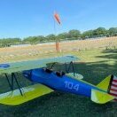
Tim Kearsley Posted March 16 Share Posted March 16 I also built the Brian Taylor Cessna 120, from the Sarik short kit. My model is based on a real aircraft, which was owned by a friend of a clubmate. A few pics attached. 2 Quote Link to comment Share on other sites More sharing options...
Richard Leech 3 Posted March 16 Author Share Posted March 16 That’s a lovely looking 120, just hope mine turns out similar. I think I’m going for white/ blue colour scheme. Quote Link to comment Share on other sites More sharing options...
Richard Leech 3 Posted March 23 Author Share Posted March 23 With previous electric conversions the IC set up is always heavier than the replacement electric set up so I'm very conscious of not creating a tail heavy aircraft, so with my build I will try to keep the tail light whilst not worrying about additional build weight up front as I hate adding 'church roof' after making a lightweight model. After careful pondering and a bit of experimenting, the following changes have been made to the fwd fuselage :- F2 has been replace with 2mm ply former as this will be the fwd frame for the removable windscreen assembly. The 1/32" ply doubler on fwd face of the balsa box sections are replaced with a 1.5mm doublers with extends to support the new F2. F3 has been cut for battery access. The 1/8" ply tank floor has not been fitted. A 3mm ply floor between F4-F5 has been added to support the standard servo's, Rx and battery tray, the servo's have been mounted 'sideways' to allow as much battery movement for CofG requirements if required. The undercarriage was the next issue - the plan shows an UC raked fwd, which in itself is not an issue, but as I had an old UC off a KK Super 60 which had the correct dimensions, it would have been rude not to use it. The supplied UC mount plate was replaced (as it had pre-drilled holes in it) and then positioned it 7.5 degrees tilting downwards at the rear, which then gave my straight UC the required rake. An additional support plate was fitted to the aft face of the mount, that can be seen in the above photo (with the lightning holes in) The removable cowl has been started but until the wings are complete, I'm reluctant to go any further as I will need to check the alignment of the windscreen. The rear fuselage section is straightforward to build, there does seem to be differing opinions on the balsa thickness of the sides! The drawing states clearly its 3/16th and drawn accordingly with sheeting top and bottom of 3/32" , the Sarik supplied upper and lower formers fit giving the required 3/32" clearance each side for the sheeting to abut the fuselage. The only tip I would give is make the formers slightly wider so you can chamfer them to make a proper mating surface. The model is well engineered in places and weak in others (that opinion is based on my flying style, runway state and ability) so with the "keep the tail light philosophy" I put lightning holes in the fuselage which also gives access if required. 1 Quote Link to comment Share on other sites More sharing options...
Richard Leech 3 Posted March 26 Author Share Posted March 26 (edited) The upper fuselage sheeting was again straight forward, I added a 1/4" longeron to support the top frames, which also gave the sheeting something to adhere to. The sheeting was achieved with 2 pieces cut from one sheet 4"x 48". The wing centre section ribs (Sarik laser cut ones) were 3/32" short with reference to the drawing, it would have been easy enough to produce replacements from the plan, but I used this to my advantage as I felt the wing attachment frame was a bit on the thin side (for my flying style !!) So I made a doubler on the aft face of the frame out of 3/32" ply. - problem solved. The aft wing attachment has been changed to 2 commercially available bolt retainers. . With the elevators and rudder, I made lightning holes to keep the tail end weight down. Edited March 26 by Richard Leech 3 1 Quote Link to comment Share on other sites More sharing options...

Recommended Posts
Join the conversation
You can post now and register later. If you have an account, sign in now to post with your account.
Note: Your post will require moderator approval before it will be visible.