


Paul Johnson 4
-
Posts
2,106 -
Joined
-
Last visited
-
Days Won
2
Content Type
Profiles
Forums
Blogs
Gallery
Calendar
Downloads
Posts posted by Paul Johnson 4
-
-
Na it's Australian.....
-
 1
1
-
-
44 minutes ago, Jim Hearnden 1 said:
Lowers & polishes halo!
Ha ha ...... yes his Halo definitely has slipped.
-
-
Could try wing cuffs on outer 70% of leading edge.
-
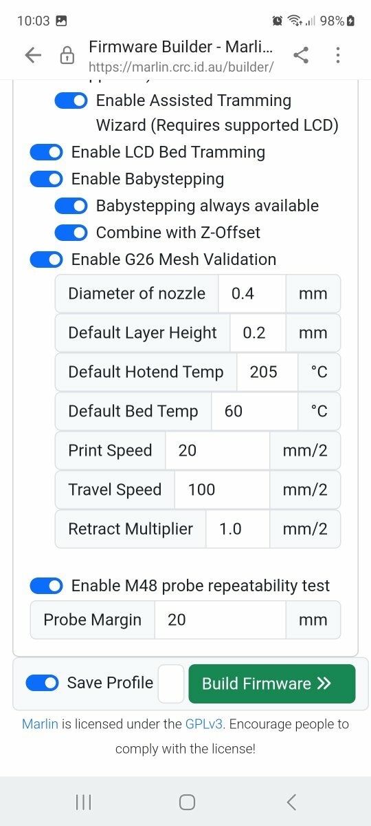
Quick example of settings available

-
Also when updating the firmware the printer needs all its E steps, probe off sets etc resetting
-
 1
1
-
-
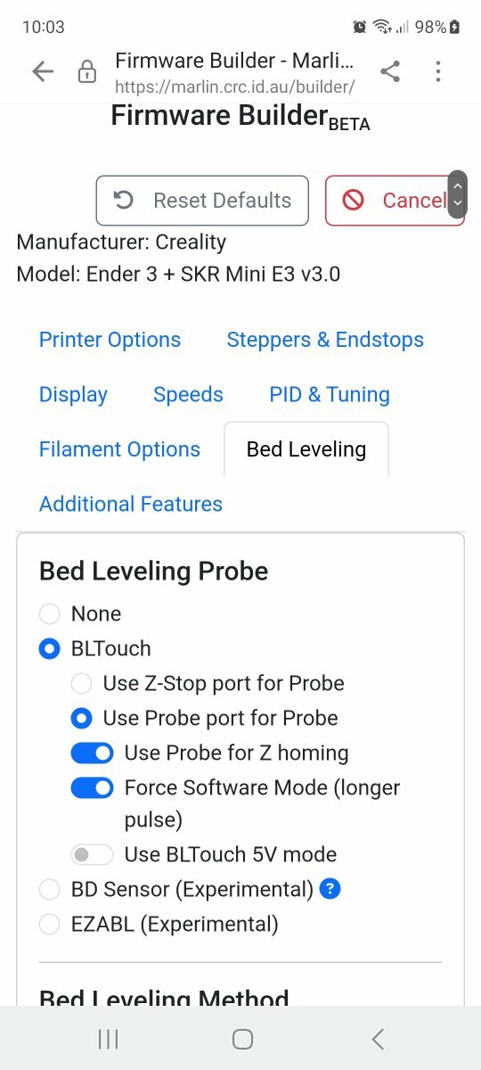
Try using the custom build page and make sure you have all the correct printer info entered. Also have you disconnected the z stop microswitch and from within the firmware builder selected to use the bltouch in its place. There is a lot of settings available from within the custom build page that are not available from the free download link, for a few dollars donation I find its worth it. Also check you have connected the bltouch correctly. I have the CR touch which is connected differently. It's usually something missed in either connecting up or firmware that causes issues.
-
1
-
-
1 minute ago, leccyflyer said:
lost a prop on climbing out
Mmm ... screw loose... I know I have
-
1
-
1
-
-
1 hour ago, gillyg1 said:
with a i/c option
No Problem.....IC = integrated circuit = Electronic Speed Controller....😛
-
1
-
-
9 minutes ago, Ron Gray said:
a dolly and belly option
Are we really talking planes here?
-
2
-
-
The plates are 1/8" Birch ply You'll break the retract before they give way..
-
1
-
-
16 hours ago, Lipo Man said:
I’d be happy with a little stick
Just stay with us and I can guarantee you'll get plenty more...
-
3
-
-
It drives master mad...
-
Ahh it's your fault then I have such acquired tastes......
-
1
-
-
As the wheel size goes up so does its thickness, the wheel as it is hasn't got a lot of room.
-
1
-
-
Na this is ugly...
-
While I think of it......the retract units are......HANDED.. so please don't think of fitting two units in one wing..

-
It may be a little while as sourcing is currently ongoing but watch this space.
-
2
-
 4
4
-
1
-
-
All these parts are then Re-exported as DXF files and sent to the Kit cutter for laser cutting.
Richard will do a blog on fitting the first one to create a guide for you to follow.
He'll probably use a chain saw so anything could happen there!
The same process is also being used to create the Tempests units.
NOW can I have my sock Master?
-
3
-
-
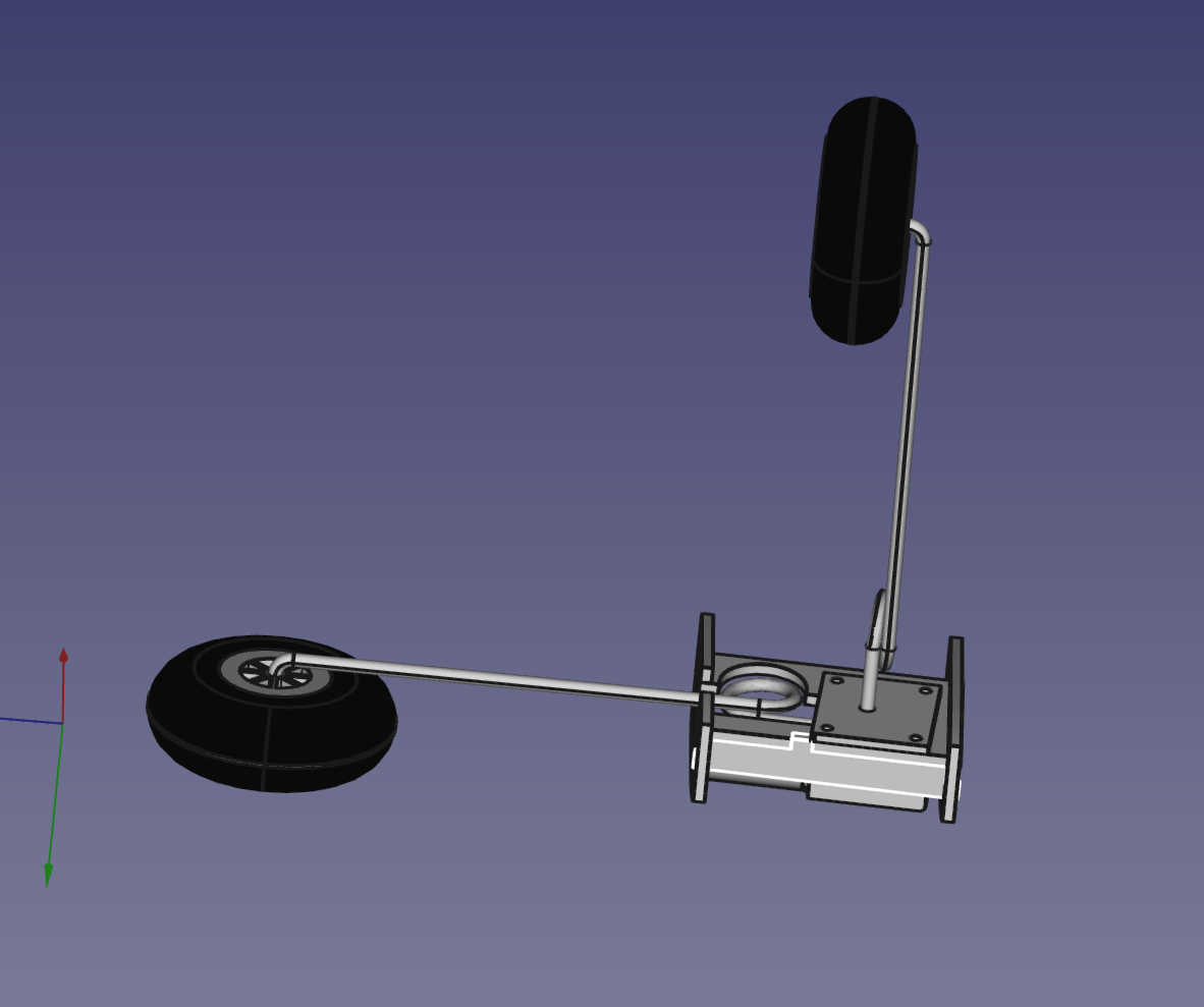
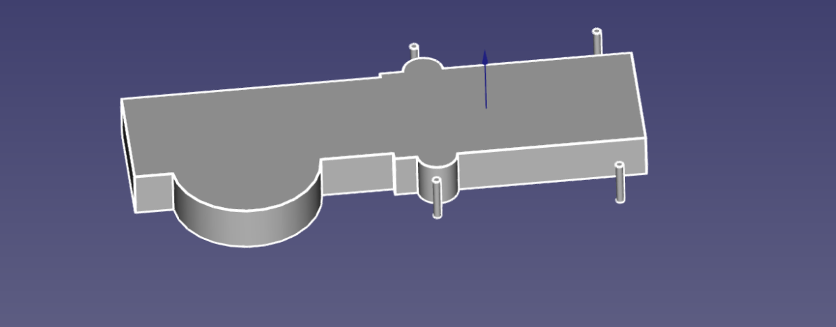
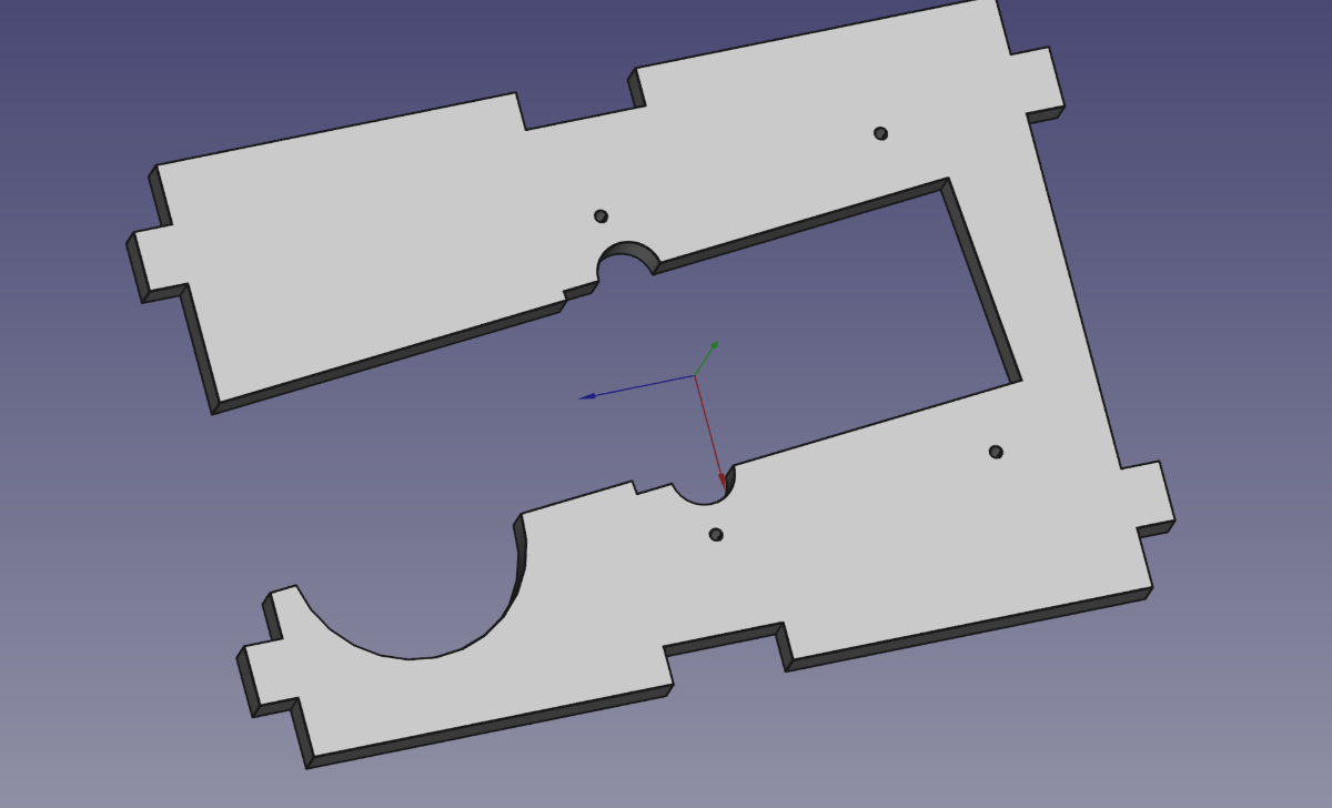
The mounting plate is 're-assembled' and a further cut made to allow for the body of the retract unit.
A Mock up retract unit with the U/C wire is then placed in position to ensure fit.
On top of this a drawing is made to create a cut out template to make your lives easier to cut out the wheel well.
the unit is designed to be fitted up to the top skin and up to the leading edge.
-
5
-
-
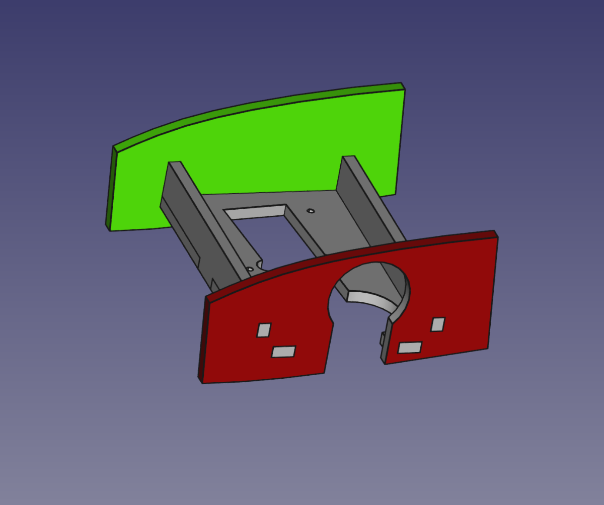
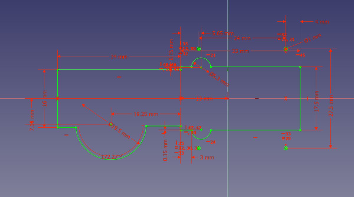
From this I can now create a plate the correct width and length to mount the retract unit on. Small tabs are added to interlock the completed assembly.
A drawing is created for the retract cut out based on the manufacturers drawing dimensions.
This is then turned into a solid part.
This part is placed into the mounting plate rotated to the correct angle .
And a cut performed to create the finished section.
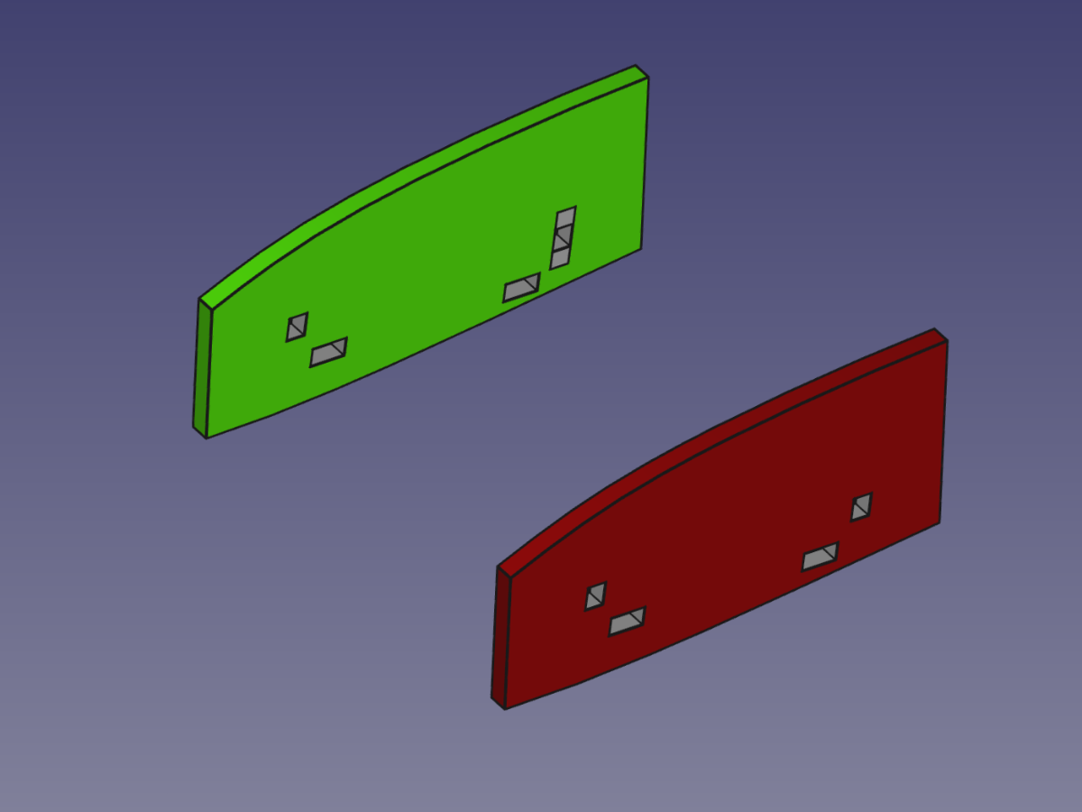
The upright supports are created as a 3D model
And the assembled unit is placed at the correct angle between the the ribs.
Again a cut is performed
-
2
-
-
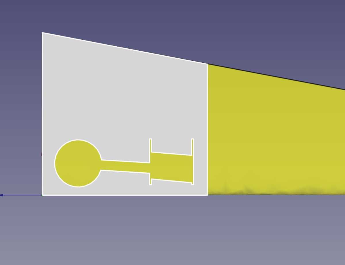
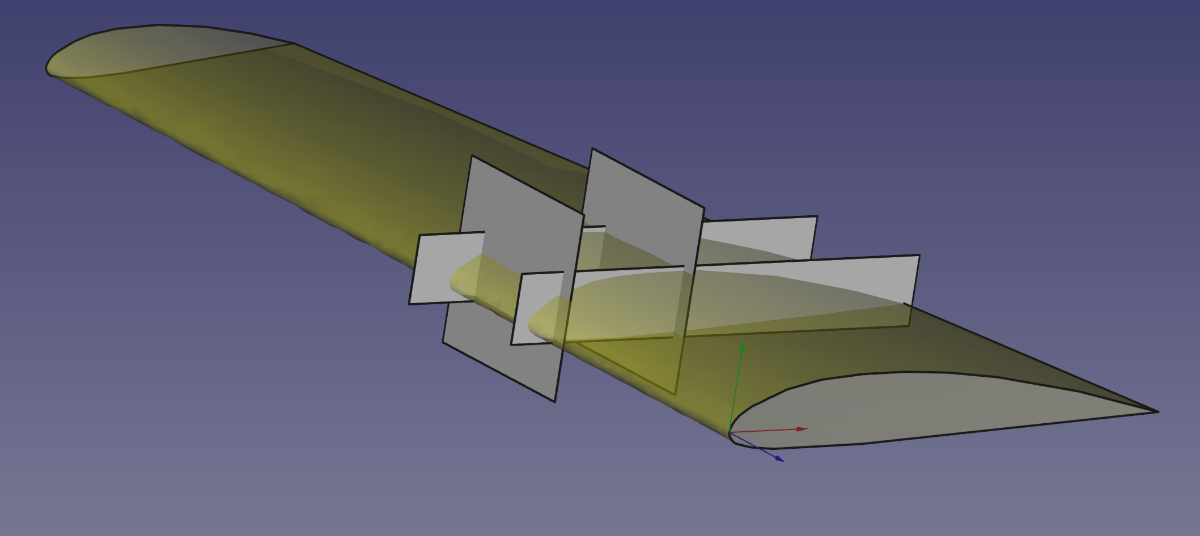
For those who thought we had forgotten you and those who are still awake this is how we developed the retract unit for the FW190.
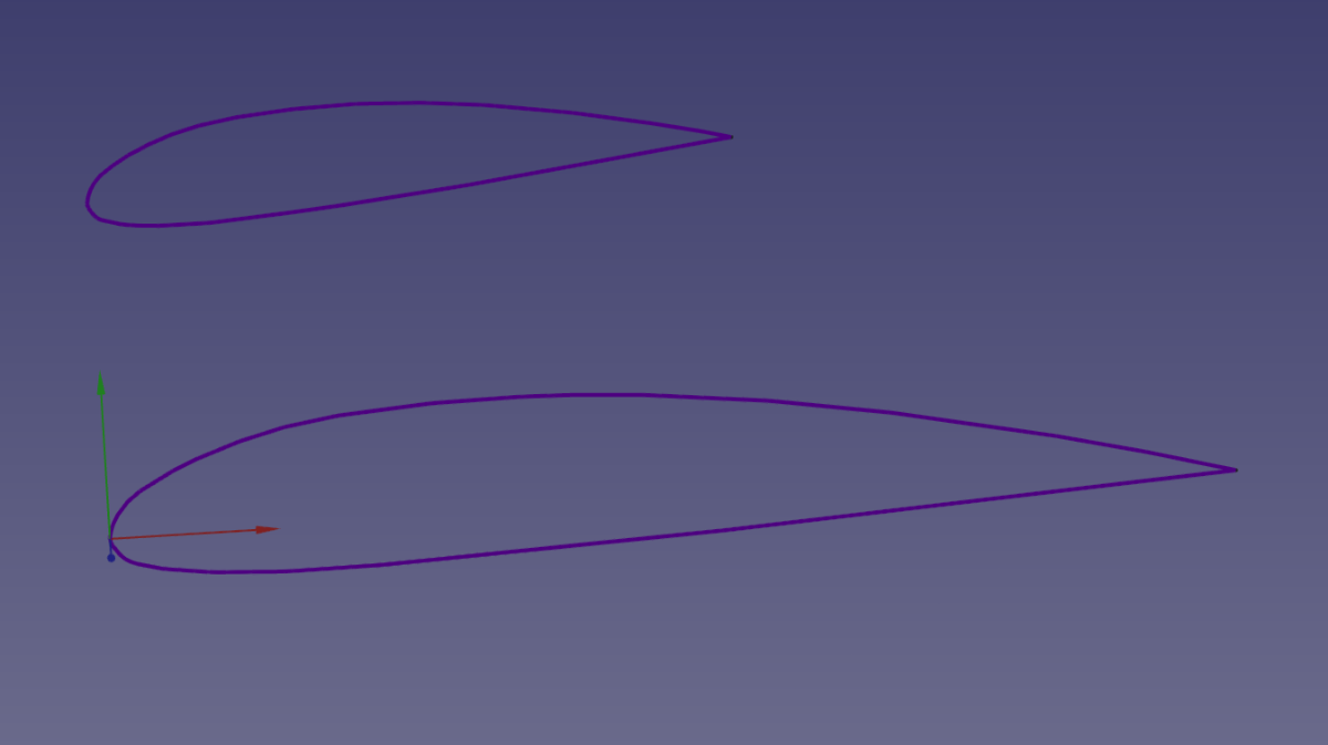
The cutting profiles used where imported in CAD as a 2 dimensional drawing in the form of a DXF file. The Wing Root and the Wing Tip. The Tip is rotated the correct amount for the washout chosen.
The outer Profile is then moved the correct distance from the Root Profile.
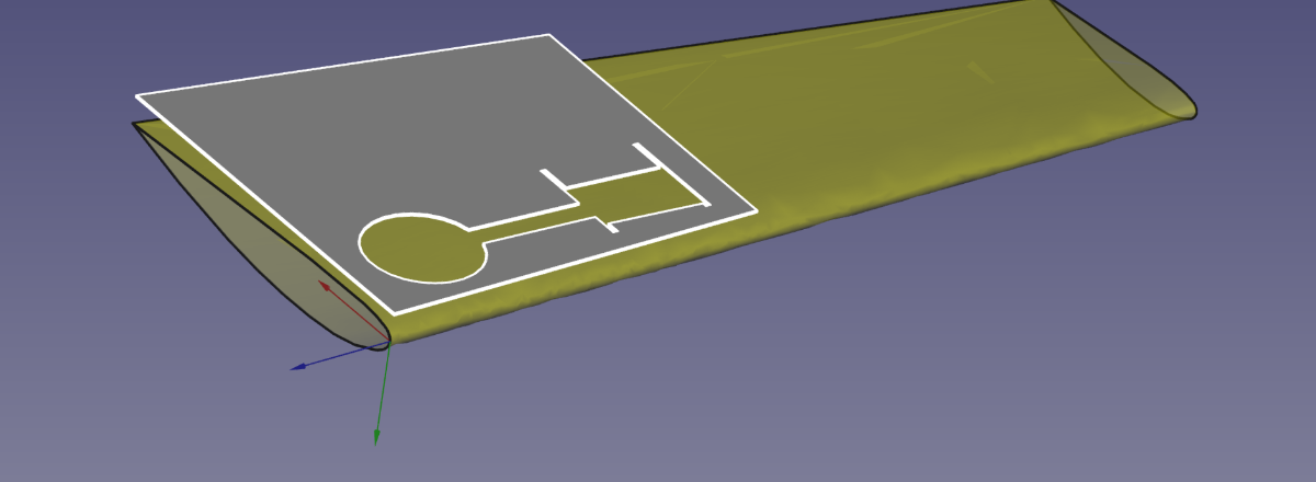
This is then 'Lofted' as a solid 3D object which is the cut foam core without the wing skin.
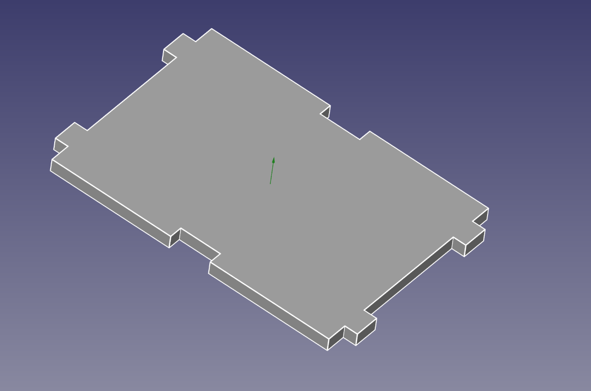
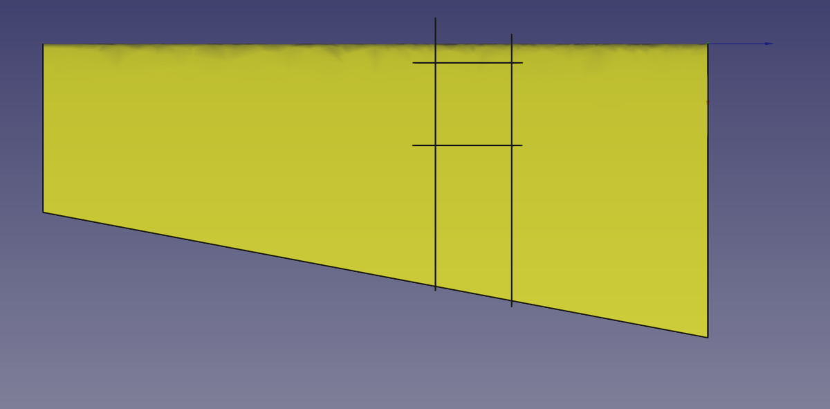
Next two planes are created across the wing to create a section that the retract plate/assembly will go in.
These plans are used to perform a 'cut' of the wing to create a section of ribs to support the retracts firmly in place
These sections are then given a thickness equal to the ply to be used to create these 'Ribs'
-
3
-
-
47 minutes ago, RICHARD WILLS said:
as people don't look at that bit .
Groan... Master is always sweeping 'stuff' in the cupboard under the stairs.. just ask Harry
-
2
-
-
I remember the first batch.... what trouble maker's they were....
-
2
-


Warbirds Replicas Hawker Tempest V -Mass Build 2024(part two) .
in Warbird kits
Posted · Edited by Paul Johnson 4
Baldrick is that you?