

Nick Somerville
-
Posts
975 -
Joined
-
Last visited
-
Days Won
8
Content Type
Profiles
Forums
Blogs
Gallery
Calendar
Downloads
Everything posted by Nick Somerville
-
First coat of Cellulose primer sprayed on the wings today. To cut it back I have used Abranet, first 400 and then 600. First time using this as I have always used wet/dry paper wet. As the cellulose is quite light it easily shakes out of the net abrasive as you rub away and easy to clean up once finished, though definitely an outdoor job. All rubbed back and ready for panel lines, access hatches/covers before a final coat of primer.
-
My old friend Canopy Glue does it’s job, with only the odd bit of smearing of that crystal clear canopy. Does anyone manage this job with no small messiness whatsoever? At least the hot weather means the glue sets reasonably quickly. A few internal parts to the sliding section have been added after painting them blue as well as some grey inner frame parts. Masked up and a trial fit before gluing the front and lower frame in place. A little filler to blend the lower edge and thankfully after the glue had set and tape removed the sliding mechanism is bind free. The cockpit area and instruments are complete
-
Woke up this morning and decided it wasn’t going to be good enough to have a fixed canopy, so spent some time rooting around the workshop. I had a length of brass tube that looked useful but the only piano wire I had to fit inside was much too tight to be a suitable sliding insert. I did have some thin pultruded carbon D section rods though and when placed together they made a lovely smooth sliding rod. Individually the rods have a little bit of flex but when glued together they are very rigid. By inducing a curve at the ends, when gluing with cyano, I was able to make up a pair of rods to fit well back against the canopy sides. As the canopy has a step at the middle it allowed me to adhere the brass tube behind the top of fixed forward section and the carbon rods at the bottom of the rear sliding section. Here I have clamped some spruce to ensure the frame stays flat along the top edge and the rod and brass have been tacked in place with cyano to the glass fibre frame. The rods run all the way through to the front of the brass tubes. with the spruce removed a fillet off Hysol has been applied around both sides of the brass tube and carbon rod. A little blob of vaseline protects the tube entries. A light spray of primer makes marking the separation lines easier. I am going to need a very steady hand make the cut using a Dremel and thin cutting wheel.
-
Leg covers now fitted and larger air rams installed for the inner gear doors. Been working on the pilots office and canopy. I made a start in a sliding canopy mechanism and had the forward rails installed, but with the roll bar and other parts couldn’t think of a way to hold/direct the rear of the canopy. So a fixed canopy I think. My Pilot is Bob Sweeney, a discontinued fella from USA Best Pilots. Bought by a modeller in Spain who sold him on to a modeller in the Czech Republic and sold on again to me. So definitely a well flown Bob 😀.
-
First time on her legs. Control surfaces held in place with tape as it’s easier to paint first and glue the hinges in afterwards. With the wing and fuselage together I have been able to test the gear with the tank pressurised and have confirmed I need to swap out the 1” travel gear door air rams for 1 1/2 ones. Those flaps are huge. At full deployment of around 50 degrees they are going to seriously slow her down. Looking a bit naked without the main leg covers in place! Good view of the cowl fixing stand off’s. The cowl snaps into place courtesy of the magnets around the tear rim and a pair of 4m allen head bolts holds it in place. No visible fixings and a doddle to remove when servicing the engine.
-
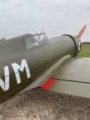
Having made the removable panels to a cess tie rear mounting bolts for the retracts I refitted the gear but found that part of the upper support just fouled on the edge of the panels when lowering tue gear. As a work around I hinged the panels and have a piece of shock cord to keep them closed. No when the gear lowers it nudges the panels and open just a few mm. Gear up panel shut. Gear lowered and the panel slightly raised. You cam also see the split air line for raising the gear and the additional small cylinder it feeds to release the down lock. Clever stuff! Here you can see the gear door ram with nylon ball connector. The 1” travel is marginal for the movement required and I have maxed out the geometry. Until I test with an air tank at 50+psi instead of just a hand pump I wont really know if it’s going to work as the doors are a bit lazy at the moment. The sequencing is managed by a UP3 valve. Amazingly clever little device that I marvel at how it must work; but work it does. Doors open- Gear down - Gear up - Doors close. Genius. So the wings are ready for a first coat of primer and rub back to pick out any imperfections. I can then add all the litho inspection hatches and panel line tape ready for primer and top coat. For anyone following who knows the duxford Bearcat you will have noted it hasn’t been painted in the correct Sea Blue as per my Hellcat. It’s a slightly lighter blue which thus far I have been unable to track down the name of. I have quite a bit of Oxford Blue Klasskote leftover from my Australian Sea Fury and this appears a closer match than the Sea Blue I have left over from my Hellcat; so perhaps I shall go with that.
-
A while later and the pinking is done on the first flap. Pinking tape supplied by Mick Reeves Models. It’s lasercut Oratex.
-
I don’t often bring work inside but as I need to sit somewhere with really good light for this task the dinning table is the best spot. Here we have flaps, elevators and rudder covered in Diacov 1000 and simulated stitching applied with pva from a dropper bottle. Once dry I can add the pinked tape. It’s remarkable that such a streamlined and late piston powered warbird still employed this covering method. I shall fit the flaps before covering the ailerons to ensure I have the gap between them spot on. Meanwhile wings and fuselage have been glassed. Photos when it stops raining.
-

Popham airfield r/c airshow May 10-11th
Nick Somerville replied to jeff2wings's topic in Shows, Club Events and Competitions
Went on Saturday for a few hours and full respect to the display pilots for battling the strong crosswind. £10 entry for OAP’s is fantastic value. Some amazing flying from the under 16 pilots and also those with long time experience. -
With the belly pan now sorted I have been working on the gear apertures and inner gear doors. After cutting out the around the main door line I realised that a hatch was required to fit the gear in/out and have access to the chassis bolts nearest the spar. The hatch has a couple of locating tabs on one side and a single screw to hold it in place. Hopefully not too obtrusive once all painted. The inner doors are hinged with three of the smaller black Robart pin hinges. Building up the inner sides proved tedious due to the convoluted shape, but they worked out quite close to the full size appearance in the end. A 1” air ram for each has been installed and connects to the door with a small nylon ball link. The fixed end of the ram will be glued in the wheel well once the wells have been painted. Still a little fettling to go, but I think I am getting close to being able to glass the wings.
-
Flaps before skinning the top surface. Thin carbon strips at t/e to help keep them true and hard after sanding to a fine edge. Blocks are for 3/32 Robart pin hinges. Finally glued in the scale aileron hinge arms into the wing. It’s almost impossible to see if the system will work until they are rigid. Thankfully all good and the internal control horn is far enough away from the hinge line to ensure a good amount of servo travel and a slop free set up. Pleased with the sharp fit of these surfaces. My Vic Rc moulded belly pan has been a bit of a nightmare and underlines my general dislike of composite models. It’s not that I don’t like fabricating composite parts myself, it’s just getting ready made parts to fit. Balsa is so much more forgiving. The rear part just wouldn’t follow the line of the model so I cut it back by 13mm and sheeted that area with 1/8th balsa. The rest has been fettled ad infinitum to conform and was probably worth the effort at it incorporated the inner doors. There is an awkward gap to fill between the cowl and the front of the pan which needs to channel air out to the oil cooler ducts. The gear doors I made have now been trimmed so I shall cut out the apertures for the retracts next and come back to that fiddly part later.
-
A bit more glass work around the wing cooler openings.
-
Has IC engines got a future anymore ?
Nick Somerville replied to flying daddy's topic in All Things Model Flying
Just found out yesterday that JE have ceased business. I gave them a call and a chap called Bob said he was in charge of looking for a buyer for all the stock. Lets hope someone can take on more than just selling bits off, but actually provide a service for owners of IC engines. Shame as they were less than 40mins from me and I had been planning to purchase a couple of their mufflers for my Valach 85 twin powered FW 190 to fit ‘in cowl’ and bring the lovely sound down to something more acceptable, to some of our club members. btw I heard at my patch recently that some of our younger modellers/members, who work in R&D for a drone manufacturer, are experimenting with building an electric powered rc model capable of breaking the world speed record for a powered model aircraft. -
Gear doors. There are two parts for these. I have an epoxy moulded belly pan, From VicRC USA that incorporates the inner doors and I think these will work fine; but the main doors supplied are misshapen, so I have had to remake these. Multiple compound cures here with wing shape and the slightly protruding bulge of the air intake. First some heat shrink fabric lightly applied to the area and a thin layer of car wax applied as a release agent. Next three layers of carbon cloth and a top layer of lightweight glass cloth laid down with epoxy laminating resin. Finally some peel ply to soak out excess resin and then some sand bags to press it all in place. Easier to do than explain.
-
Both sides of the wings are now fully sheeted and today with lovely spring weather was able to use space outdoors to finalise the wing to fuselage fixing. Usual dowels at front and hold down bolts at the rear.
-
Getting ready to skin the lower starboard wing. Servo hatch apertures framed and then paper template made and taped in place behind the trailing edge. With the made up skin in place the templates fold down to allow accurate marking. Once the flap and aileron servo mounts are in I can glue the skin in place.
-
Would make total sense to learn how do 3D drafting. However, I spend long enough on my mobile and the thought of more screen time doesn’t appeal so I plod on with the old school trial and error method. I must be a bit more right brain biased despite enjoying logic. Mind you, l anyone who have mastered cad have my utmost respect.
-
Nigel, I will take a photo tomorrow of the gear extended.
-
Turning my attention to installing the retracts into the starboard wing half, I referred to the plan that showed both scale articulated and sport versions. The sets of ply forward ribs for the area appeared to be correct for the scale retracts I have and I added bearers that I had made from maple, gluing them in with Loctite EA 9461. This is a dark grey (2 part black and white) thixotropic epoxy aka Hysol that is by far the strongest adhesive I have come across; albeit impossibly messy to use. Clearly I hadn’t thought this through as when offering the retracts to the mounts there was a number of substantial openings that needed to be made in the central pair of ribs to clear all of the protruding and moving parts of the complex retracts. By the time I had created the necessary clearances the forward bearer had little to hold it in place and so an additional ply plate was added to support it. I also added carbon cloth to the area to mitigate against shock waves splitting the top surface. Once this had been achieved I then realised that the angles were way out. With the combination of the immensely strong adhesive and rock hard maple bearers this became a mighty tedious task to rectify. Hours later I achieved a good fit and although not pretty I am confident in the integrity of the installation. The port wing installation should be a much more simple task with the hindsight. The bearers will be drilled and tapped for the 4m fixing bolts; another reason for using maple.
-
Unusually for Jerry’s plans there are no drawings for scale aileron hingeing, though the flaps have a good semi scale representation of the movement. I referred back to the method employed for my Hellcat and despite the tedious work involved managed to make the parts needed from some G10. To cut the parts I drill 1.5mm holes around the drawn shape, snap out with pliers and then clean up with file and a small sanding block. Both the wing and ailerons have required some reworking to depart from the sport hingeing shown on the plan; but the extra work will be worth it to hide the actuating pushrod and have it properly shrouded. An added benefit will be easily detachable ailerons as they pivot on 3mm bolts.
-
The fuselage has all been sheeted bar the few areas around the exhaust outlet areas that will be aluminium. Fin glued in place and carbon lay up done over the tailwheel door area. Cowl engine baffle added and stand offs to hold the cowl in place as per Hellcat. One thing I have learnt building warbirds is to have a simple quick way to remove the cowl. Rather than press on with completing the fuselage I want to get on with the wings to ensure that the wing saddle is a good fit. Time to tidy the bench then! Definitely a happy place laying out all the parts for a new wing. Pretty straightforward apart from a few of the outer ribs having incorrect cut outs for the spars. Easily rectified and an email sent to Jerry Bates so he can amend his files. A couple of hours later.
-
Top half now sheeted, though have left out the exhaust areas and some lower adjacent areas. These will be in metal and pro-skin to simulate the exhaust and engine bay access panels more realistically. Upside down view. Bottom air escape windows will channel the air through to the oil cooler exit. Other exits are the exhaust stacks and cowl flap exits. Once the Hysol has cured I can fit the engine baffle plate. Lower formers added and wing hold down in place. Fuel tank, Air tank (there will be a second air tank in the wing alongside the retract valve) and servos for choke and throttle mounted. Servos positions for elevator rudder / tail steering and tail retract finalised, though just using some old servos for now to align control runs. I shall leave the lower skins off until after fixing the stab, fin and moving surfaces to ensure accuracy of all linkages. cowl ring glued in with Hysol. It has 6 sets of 3x stacked 10mm neodymium Magnets that align the cowl to the firewall that in turn has 6 x single magnets installed. Boy does it lock in place.! Tail retract will be pushrod operating. I have some holes to drill and tap in the chassis for centring springs and for the two part covers to affix to.
-
Hi Tony, interested in your build as I did the 1/4.5 Vailly Fw190 a couple of years ago. The 1/4 is a Big model; what engine will you be using? Sierra retracts I’m guessing.
-
Any 1/4-1/5 scale balsa electric kits recommended
Nick Somerville replied to Christopher Morris 2's topic in Scale Matters
If you fancy a biplane the Slec Stampe is great flyer and enjoyable build -
First steps on the fuselage have been made. Firstly top formers F1 through to F7 were glued to inner 1/8 ply plates that had been trimmed back at the front. This was to reduce the engine box in lieu of the stand off’s I will be mounting the engine on. The firewall is 1/4 ply with a 2mm carbon sheet laminated to the front. The cut out and small hole below accommodate the carb Venturi trumpet and pushrods for both throttle and choke. The upper longerons are yet to be glued as they don’t yet follow a good line and a few formers need adjusting. I use a length of spruce 1/4 sq to check the lines as it holds a very smooth curve. for the rear of the fuselage a crutch of 1/4 sq balsa longerons were pinned to the plan and remaining formers glued in place. To fit the front and back together spacers were used to allow the wing saddle to protrude below the crutch. I wouldn’t call this ideal practice, but it seems to be working out and regular checks for alignment with a laser line helps maintain confidence.
