

Richard Thornton 2
-
Posts
153 -
Joined
-
Last visited
Recent Profile Visitors
619 profile views


Richard Thornton 2's Achievements
80
Reputation
-
The foot rests on the float struts.
-
More detail (weight!) added this week now it’s warm enough to paint.
-
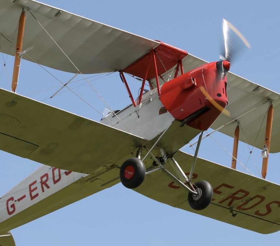
Thanks Nick. That’s what I was really concerned with the original concept with these floats. It’s a large model, it’s has weight. It needs added speed to take off on water and water at this speed is ‘hard’. Hence the backing with polystyrene which gives strength in both longitudinal and compressive areas
-
Many thanks Yaho
-
They are massive floats but are the correct size for the model, or put another way, line up with the photos I have. I am really concerned about the weight but being a Tiger Moth, should cope….fingers crossed
-
Question, what WBP glue do you use. I had some from work years ago, powder form and it was fantastic but it was only an eggcup full.
-
Thats the way i am leaning towards. Many thanks and the use of epoxy means the house doesn’t stick for weeks and I don’t melt the polystyrene
-
Good point
-
To give size to the ‘issue’ 😏🙈🙊🙉
-
Very good point. So let me be more specific, the floats are not for an ARTF. They are light ply formers, hard wood stringers and foam white polystyrene infills to give the shape and support to the loaded areas ie underside. A picture says a 1000 words but having looked at the photo I took, my model seems to have gone backwards in construction rather than forwards. Each stage needs general arrangement, to a degree, prior to final completion, finished coatings and re assembly. I have a dreadful habit of doing things twice. First time seems to be to get things in the right place, then take it all to pieces, modify it to look more scale like before putting it all back together.
-
Thanks Frank. Good advise. I have a foamy model Tundra from Hobby King that has foam floats and that’s the L plate water plane for the larger model. The floats I want to cover are already starting to put on weight so hence the question regarding covering. Also the issue of balsa on the underside compound curves keeps me awake at night!
-
Evening all. Help required covering polystyrene foam floats. I have tried to get to the bottom of this but there seem to be so many options. Fibre glass cloth using epoxy resin. Fibre glass cloth using resin (don’t want to go down this option!) Fibre glass using waterproof pva or Brown paper using epoxy Brown paper using pva glue. or Light balsa…. As above. I realise using the brown paper method involves shrinkage so doing curved concave and convex surfaces will not work? No idea where to start. Any suggestions?
-
Well that’s todays project over and completed. There is a bit of a ‘touch of the cap’ to the aircraft’s origin 1946 to 1959 and to its current 1959 to present day.
- 141 replies
-
- 4
-

-
- tiger moth
- 1/4 scale
- (and 2 more)
-
Thanks Peter, I was wondering how you did yours. I am also using Solartex which I bought about 15 years ago. It is painted silver on the outside as silver spray painting is horrid. I have, like you, painted all the inner wooden struts and frames green and was hoping that coating the ‘contact’ surfaces with ‘Cover Grip’ to aid the sticking process. My thought was, as it’s painted on the outside would it be possible to paint it on the underside, so I am going to get some offcuts and experiment.