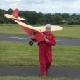
David Davis Posted August 1, 2018 Share Posted August 1, 2018 Introduction. I built my first successful radio controlled aircraft in 1988, a Flair Junior 60 powered by an Irvine 20 car engine. I was influenced in my decision after having read the late Peter Russell's book, "Vintage Model Aeroplanes" in which he extols the virtues of Dr Walt Good's "Big Guff." Since then I have always had a soft spot for the Big Guff. It was one of the very first radio controlled model aeroplanes having flown for the first time in 1938 or 1939. It has an eight-foot wingspan and Mr Russell's model was powered by an OS 60 FS, the type with the exposed valve gear, when I photographed it at Old Warden in 1988 or 1989. I bought a reduced-size plan at the time but spool on thirty years and I have ordered a short kit with a full-size plan from Laser Design Services in the USA which was posted yesterday. Over on RC Groups a chap called Sherwood Heggen built a Big Guff. The following link shows the fuselage under construction. **LINK** The original Big Guff did not have ply doublers in the nose, either these now come with the kit or Mr Heggen fitted them to strengthen the nose on his own inititiative. According to the original plan the fuselage is sheeted with 1/16" balsa from the firewall to the wing trailing edge, grain vertical, and then the complete fuselage is covered in 1/32" sheet, grain horizonal. Mr Heggen chose to cover the fuselage in 1/16 balsa and omitted the 1/4 sq balsa horizontals between the fuselage sides. My Dilemma. Should I cover the fuselage in 1/32" sheet as per plan or in 1/16"? 1/16" will be stronger but heavier and will require extra nose weight to get the model to balance. I/32" may be rather brittle, besides I have not used such thin balsa wood for over fifty years! Similarly, the wing leading edge sheeting was originally 1/32". Should I substitute 1/16"? I plan to cover the model in Solartex and to power it with a Laser 70. Quote Link to comment Share on other sites More sharing options...
David Davis Posted August 5, 2018 Author Share Posted August 5, 2018 I have tracked the kit to Charles De Gaulle airport so it should be delivered in the next few days. I'm feeling quite excited about it and I'd better withdraw some cash to pay for the Value Added Tax and any Import Duties! Apparently the proprietor of Laser Design Services has sold another five short kits of the Big Guff so I am now a member of quite an exclusive little club. I plan to cover it in Solartex and to power it by a Laser 70. I have a Laser 80 sculling about doing nothing, I could fit that and being much heavier than the 70 it would help with c/g problems which are encountered with such short-nosed designs. However, a Laser 80 would seriously over-power the model especially when you consider that Peter Russell's Big Guff was quite adequately powered by an early open rocker OS 60FS. Last year I made a complete Horlicks of a landing while flying my WOT 4 XL, dropping it in from at least two metres and breaking the fuselage in half. I was literally about to throw it onto the bonfire when I decided to find out the cost of a replacement. At £183 (€206 or $238 US) I decided to repair it and to fit an old Laser 150 V twin in place of the Enya 120 FS I had previously used. I have glued the two fuselage halves together in a SLEC gig and reinforced the joints. With the V twin up font it looks like something out of Mad Max! Once it's off the bench, the construction of the Big Guff can begin! Quote Link to comment Share on other sites More sharing options...
David Davis Posted August 14, 2018 Author Share Posted August 14, 2018 Just a note to say that the shortkit arrived safely and in good condition from Bob at Laser Design Services yesterday morning at 10.12 local time. **LINK**Photos below. 1 metre rule lends scale to the plans. Two days to get from Texas to Chicago O'Hare, six days to clear customs in Paris and a further five days to travel the 220 miles (353 kms) to my house in La Creuse. Vive La France! Mind you, four of those days were weekends and two were Mondays. It cost me an extra €38 in taxes and import duties (S43.35 US or £33.82 Sterling.) It's certainly big enough with its eight foot span, five foot six inch fuselage length and fifteen inch chord! ( 2.4 metres, 1.58metres and 38cms respectively.) I have a number of decisions to make about its construction. The wing as built by Walt Good had two full-depth 1/8" balsa spars at approximately 25% and 75% chord. For me to replicate this method would involve cutting each one of Bob's lovely laser-cut wing ribs into three parts. I am going to modify the construction to a more conventional 1/4" square spars with shear webs in the postions where the original spars were, but should I use balsa or something a little stronger like basswood for the spars? As for the fuselage, I think I am going to build it as stock. Sherwood Heggen's version is certainly stronger with its plywood doublers and 1/16" sheet covering but I think I am going to go with the original structure; 1/4" stick fuselage, forward section covered in 1/16" sheet balsa, grain vertical, and the whole thing covered in 1/32" balsa grain horizontal. I haven't used 1/32" balsa since I built a competition free-flighter called a Gossamer about fifty-eight years ago which was not a success, but if I crash it I'll break it anyway and if I can't fly a three-channel vintage model after thirty year's flying experience, I should give up the hobby! I may extend the side cheeks to allow for the long crankshaft of the Laser 70 and incorporate a little extra downthrust as the Laser may be a little more powerful than Sherwood's Saito 65. Some claim that you could simply build a stick fuselage and reinforce the nose with ply doublers then cover the fuselage in silk, nylon or Solartex. Doubtless this would work but would it still be a Big Guff? As for the radio installation I will use standard servos as far forward as possible to actuate the rudder and throttle and fit a micro servo in the tailplane for the elevator. I could easily fit a standard servo on its side in the forward fuselage for the elevator and use closed loop cables but the "up" cable would have to exit the fuselage well forward of the tailplane and it would look rather unsightly in my view. I will probably go for an HS 82 MG metal geared servo for extra peace of mind. I know I will not be performing aerobatics with this model, it's just a belt, braces and piece of string sort of thing. I have followed Sherwood Heggen's build log with great interest and he has already privately given me some advice on the build. If my model comes out as successively as his I'll be very satisfied. Once I get three repairs out of the way and finish off a Baron I intend to give as a gift, I'll make a start. Any advice will be gratefully received. Quote Link to comment Share on other sites More sharing options...
Don Fry Posted August 14, 2018 Share Posted August 14, 2018 I would stick to the Laser 70. In power output it's in the same region as an open rocker 90. So you won't lack oooph with the 70. Quote Link to comment Share on other sites More sharing options...
David Davis Posted August 14, 2018 Author Share Posted August 14, 2018 No I'm not a purist Dave Mellor. When you talk of "cap strips" do you mean a continuous 0.5mm x 3mm carbon strip along the entire half span, ie from the centre section to the wing tip? That's certainly a possibility and it would make the wing extremely strong. However, I will probably go with 1/4" square or 1/4 x 1/8" for the main spars of the wing. There's no reason why I shouldn't reinforce them with 0.5 mm x 6mm carbon strip. I have only one slight reservation. The black colour of the carbon fibre would show up throught the vintage covering material, furthermore I will not be throwing this model all over the sky like a WOT 4. I'll give it some serious thought though. Quote Link to comment Share on other sites More sharing options...
Nigel R Posted August 14, 2018 Share Posted August 14, 2018 Massive thick wing like that, I'd use 1/4" sq full span. Doubled up with another 1/4" sq to about 1/3 span. Pop some 1/16" or 3/32" webs in between and it'll be rock solid. If you're feeling a bit squeamish about balsa on something this big then go with basswood or spruce. I'd stick with 1/32" to sheet the fuselage. Or build it out of 3/8" sq instead and omit the sheeting altogether, and use diagonal truss bracing. One thing I wouldn't do is a HS82 on elevator, but, your call, I'd prefer a beefier gear train, at six foot long I would be at some serious risk of hangar rash killing the servo, and it's not like the weight saving is that critical with an actual entire acre of wing area. Or maybe use two micro servos one for each half. Or, could you use an internal torque rod type joiner (or two regular aileron torque rods) if you're wanting to hide the mechanics a bit? Quote Link to comment Share on other sites More sharing options...
Don Fry Posted August 14, 2018 Share Posted August 14, 2018 Having a think, you don't need an UP cable on the closed loop for the elevator if you fly it as stated. A spring would do the job. To be fair, once trimmed you would not touch the elevator in flight, rudder and throttle only, with a bit of trim on the elevator depending on how much speed you want that day, to suit the wind. Save weight at the back. Quote Link to comment Share on other sites More sharing options...
Keith Evans 3 Posted August 14, 2018 Share Posted August 14, 2018 David ,-----I have just completed a "SNOWY OWL " by Andy Lennon and the flaps ,ailerons , vertical fin which supports the elevator assy. ,rudder and elevator are all skinned with 1/32" balsa .I ,like, you was worried about this but went ahead .The finished components surprised me by how much strength they had .I'd carry on with it Quote Link to comment Share on other sites More sharing options...
David Davis Posted August 14, 2018 Author Share Posted August 14, 2018 Don a micro servo wouldn't weigh much and I feel the need for up elevator to flare the landing. My landings are bad enough anyway. Quote Link to comment Share on other sites More sharing options...
Don Fry Posted August 14, 2018 Share Posted August 14, 2018 Arrrrrrrrr, but the spring does the up. A micro servo, 9 grams, is 50 grams of lead on the nose. Quote Link to comment Share on other sites More sharing options...
Nigel R Posted August 14, 2018 Share Posted August 14, 2018 But Don, this thing has ten square feet of wing. You could carry a breezeblock around in it and not notice! I vote for one servo per side, hidden just under the tailplane, with one single pushrod apiece. No joiner needed. Quote Link to comment Share on other sites More sharing options...
David Davis Posted August 14, 2018 Author Share Posted August 14, 2018 Nigel, the elevator is one-piece. Quote Link to comment Share on other sites More sharing options...
David Davis Posted August 15, 2018 Author Share Posted August 15, 2018 Dave Mellor, thank you for your advice. I'm giving your ideas some consideration but never having used carbon fibre strip before, I have a few questions for you. What adhesive would you recommend for attaching the carbon fibre strip to the spar? I will be using basswood for the spar. Given that the depth of the wing rib at the spars is 2" and just over 1.5" and given that I will be fitting the carbon fibre on the inside so that its black colour does not show through the translucent covering, which glue would you recommend for attaching the shear webs to the carbon fibre strip? Would you recommend 1/4" square basswood for the spars or would 1/4" x 1/8" be sufficient? What thickness balsa wood would you recommend for the shear webs? Given that the spars will be 1/4" or 6mm wide, can you recommend a supplier who could sell me carbon fibre strip in this width? Quote Link to comment Share on other sites More sharing options...
Nigel R Posted August 15, 2018 Share Posted August 15, 2018 Ah! I'll pretend I didn't say anything about multiple servos then! David If the original spar is 1/8" x 2", an equivalent volume of wood is present in 2 off 1/4" x 1/2" balsa spars, broadly equivalent to 1/4" x 1/4" spruce/basswood by themselves. With them being spaced apart and turned into an I beam by webs, surely that alone is more than the original design. Presumably with carbon tow on the inside surface they could be dropped in size to 1/4"x1/8", but how much carbon would one need to maintain strength? Quote Link to comment Share on other sites More sharing options...
David Davis Posted August 15, 2018 Author Share Posted August 15, 2018 Thanks for the advice Dave, you're quite right I won't be subjecting this model to the stresses of aerobatics, I have other models which will allow me to do that. One further point though. If I were to use the carbon fibre strip on the inside of the spars, for appearence sake, the shear webs will be attached to the carbon fibre. In this case I presume that I would need to use epoxy resin. Quote Link to comment Share on other sites More sharing options...
Piers Bowlan Posted August 15, 2018 Share Posted August 15, 2018 Ask ten modellers how you would build The Big Guff and you will get a dozen different answers! Personally unlike David (Mellor) I wouldn't bother adding carbon strip or towes for that matter. If you are intending to use quarter inch Bass wood for the upper and lower members with full depth webbing, it will be massively stronger than this slow flying, lightly loaded model will ever require. The question that David asks is a valid one. Would 1/4 x 1/8 basswood be sufficient - and without carbon reinforcement? After all, the original design used an all balsa spar glued together with balsa cement and carbon fibre hadn't been invented! I would give some thought to how the two wing panels are joined. The dihedral braces on some of these early designs are somewhat fragile by modern standards, think, Super Sixty (howls of protest on the forum!). A lot of leverage with large wings, should they suffer an arrival rather a landing, so make sure there are not any stress risers. With a short nose moment, why put any servos in the tail, just use wire trace and pull pull cables? That way you can use any servos you like in the fuselage without fretting about the weight. Personally, I would use a wire U shaped joiner for the two elevator halves, more reliable than a piece of wood. I think the Laser 75 will be more than adequate! Personally I would go electric and stick the LiPo vertically behind the motor bulkhead. No C of G issues even if you covered the entire rear fuselage with birch ply . Quote Link to comment Share on other sites More sharing options...
David Davis Posted August 15, 2018 Author Share Posted August 15, 2018 The wing panels are actually bolted together with little brackets which are screwed and glued to ply reinforcement of the main spars. You can just see them poking out above the top of the wing in the photograph of Peter Russell's model. Peter Russell used paxolin to make up his brackets, Dr Walt Good used steel on the original and plywood brackets have been provided with the kit. I will make up a set of steel ones. As for the elevator, I refer the honourable gentleman to the answer I gave earlier concerning the Big Guff's elevator. It's in one piece! As for actuating the elevator I'm leaning towards a standard servo well forward and a 1/4" square hard balsa pushrod supported by two or three light balsa "diaphrams" to prevent it from bending. After all, this is not a pattern ship and it will spend all of its life taking off, flying slow circuits and horizontal eights and landing again. Besides a 1/4 square pushrod was what Mr Russell used in his Big Guff and what was good enough for him is certainly good enough for me. ( Source: "Vintage Model Aeroplanes" by Peter Russell, page 47.) Edited By David Davis on 15/08/2018 09:58:01 Quote Link to comment Share on other sites More sharing options...
Nigel R Posted August 15, 2018 Share Posted August 15, 2018 Terry Westrops Loaded Dice era pattern designs used to spec a 3/8" hard balsa pushrod for the elevators - that seemed to work out ok for him. Dave M - I forgot to account for the webs! So my original guess of 1/4" square hard balsa + webs, was about right. David D - I assume the wing has no sheeting and all twisting loads were resisted by silk/nylon (tex?) covering? Quote Link to comment Share on other sites More sharing options...
David Davis Posted August 15, 2018 Author Share Posted August 15, 2018 Nigel R, the Big Guff's wing and tailplane are partially sheeted with 1/32" balsa on the upper surfaces. You may also see the metal brackets holding the wing together on this picture of Sherwood Hegen's Big Guff. Here is another picture of his wing. Edited By David Davis on 15/08/2018 14:55:05 Quote Link to comment Share on other sites More sharing options...
Nigel R Posted August 15, 2018 Share Posted August 15, 2018 Thanks David. I checked outerzone which has a very low res reduction of the plan but couldn't see this detail. I'd be tempted to box in the LE underside to form a D box. I would guess a lifting tailplane section? Dave M "the original full depth spar maintained full vertical continuity along the length of the span. The new I-beam method (to avoid cutting the ribs into 3 parts) does not. So the spars of the "new" I-beam now have to do that job if one of the many ribs or rib/shear-web joins should fail under load." I'm not 100% clear what you mean by verical continuity here, can you clarify a bit? Quote Link to comment Share on other sites More sharing options...
David Davis Posted August 15, 2018 Author Share Posted August 15, 2018 Nigel, the tailplane has a symmetrical section as does the fin of course. Quote Link to comment Share on other sites More sharing options...
David Davis Posted August 16, 2018 Author Share Posted August 16, 2018 Thanks for all of your advice gentlemen. I have decided that a model of this size and weight, (my target 7lbs or 3.17kgs,) does not require the builder to save every gramme. Furthermore, it should be easy to fly and with its undercambered wing section it will fly pretty slowly, so I don't think that it will require any extra strengthening like ply doublers in the nose for example. After all, the original weighed 8lbs, (3.6kgs) and it was designed to carry radio equipment weighing 2lbs (0.9kgs.) Therefore, the fuselage will be built as per Walt Good's original, the tailplane will be built on the egg box principle, a series of half-joints, the elevator will be actuated by a balsa pushrod, the rudder by closed loop cables and standard servos will be used as far forward as possible. I have thought long and hard about the wing structure and will either use 1/4" basswood spars, (sorry can't bring myself to trust even hard balsa!) with balsa shear webs, or a sandwich of two lengths of 1/4" X 1/8" balsa with carbon fibre strip in between them, again with sheer webs in between the spars. The rationale for this sandwich is that it allows wood to wood joints both between the spars and shear webs and between the spars and the wing sheeting. A wood to carbon fibre joint would require the use of epoxy which is not as easy to use a an aliphatic glue in my view. I like the idea of shear webs with the grain at 45 degrees but my own sense of spatial awareness is notoriously poor and I can imagine me wasting a lot of wood if I were to adopt that method. Besides the conventional way of using shear webs with the grain running vertically will certainly be strong enough. Incidentally, Sherwwod Heggen's Big Guff with an all painted finish initially weighed an enormous 11.25 lbs or 5 kgs. He stripped off all of the covering and replaced it with Vintage Orange Solartex and managed to get the weight down to 9.25 lbs (4.2 kgs). even at this weight the model flies well. Thank you once again for all your advice gentlemen, I'll keep you up to date with the build when I start. Quote Link to comment Share on other sites More sharing options...
Barry W Posted August 16, 2018 Share Posted August 16, 2018 David There is an interesting article on The Big Guff in this months US Model Aviation Magazine. It talks about the 20 year old twin brothers Bill and Walt Good who built the Big Guff as well as the radio equipment. The plane is considered to be the first designed specifically for Radio Control in the US. The plane won the US RC Nats. in 1938,39 and 40. A version of the plane and radio equipment is on display at the US Model Aircraft Museum in Muncie IN. Muncie is a bit off the usual US tourist route however it is possible to see the plane if you do a virtual tour of the museum. Type in modelaircraft.org/museum then click on museum and then go to virtual tour. Then find your way to the model shop and the Big Guff is hanging above the entry. It looks as though this model has "polydihedral" (sp) probably to give it some better flight stability. If you are interested email me your address and I will try and scan and sent you the article. I also think Big Guff looks like a big brother to Sparky a plane I built from an Aeromodeler plan which is on the list here and was first published in 1951 Quote Link to comment Share on other sites More sharing options...
David Davis Posted August 17, 2018 Author Share Posted August 17, 2018 Interesting. Both the Guff and the Big Guff are featured in the museum. The Guff pre-dated the Big Guff and is a smaller model with a six foot (1.8 metre) wingspan and polyhedral wing. Apparently the Big Guff in the US Model Model Aircraft Museum is a replica. The original is in the Smithsonian. Quote Link to comment Share on other sites More sharing options...
David Davis Posted September 8, 2018 Author Share Posted September 8, 2018 I'm just accumulating materials necessary for the build of the Big Guff and I see that the undercarriage on the American original was made from, "1/8 inch spring steel wire." Is that the same as 8swg? The model will probably weigh about seven pounds. Quote Link to comment Share on other sites More sharing options...

Recommended Posts
Join the conversation
You can post now and register later. If you have an account, sign in now to post with your account.
Note: Your post will require moderator approval before it will be visible.